
Owners Manual
Page 4
TABLE OF CONTENTS Maintenance Safety Precautions ...25 Suggested Maintenance Procedures 25 Transporting the Invacare Patriot...26 SECTION 5-FRONT RIGGINGS 27 Installing/Removing Swingaway Footrest 27 Installing Swingaway Footrest ...27 Removing Swingaway Footrest ...28 Adjusting Swingaway Footrest Height 28 Removing/Installing Heel Loops ...28 Removing Heel Loops...28 Installing Heel Loops ...29 Installing/... Upholstery 38 Installing/Removing Seat Positioning Strap 39 Installing/Removing Chest Positioning Strap 40 SECTION 8-REAR WHEELS/FRONT CASTERS 41 Patriot™ 4 Part No 1088909
TABLE OF CONTENTS Maintenance Safety Precautions ...25 Suggested Maintenance Procedures 25 Transporting the Invacare Patriot...26 SECTION 5-FRONT RIGGINGS 27 Installing/Removing Swingaway Footrest 27 Installing Swingaway Footrest ...27 Removing Swingaway Footrest ...28 Adjusting Swingaway Footrest Height 28 Removing/Installing Heel Loops ...28 Removing Heel Loops...28 Installing Heel Loops ...29 Installing/... Upholstery 38 Installing/Removing Seat Positioning Strap 39 Installing/Removing Chest Positioning Strap 40 SECTION 8-REAR WHEELS/FRONT CASTERS 41 Patriot™ 4 Part No 1088909
Owners Manual
Page 8
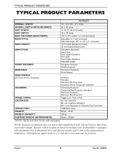
...20 inches 16 or 18 inches 15½ to ‐floor height. NOTE: Invacare recommends that rear seat‐to‐floor heights be at least 3/8‐inch shorter than... Back (Standard) Space Saver Desk Length (Standard) Full Length Fixed Height (Standard) Adjustable Height Swingaway Footrests Elevating Legrests Permanent (Standard) Quick-Release REAR WHEELS: 20, 22 and 24 inch Composite HANDRIMS: WHEEL...Urethane (Standard) 8x1¼ inch Pneumatic or Pneumatic-Flat Free Insert U240 Black Nylon Patriot - 29 lbs 250 lbs Patriot - 39.5lbs* *NOTE: 16x16 inch Seat Frame with flat free inserts, add...
...20 inches 16 or 18 inches 15½ to ‐floor height. NOTE: Invacare recommends that rear seat‐to‐floor heights be at least 3/8‐inch shorter than... Back (Standard) Space Saver Desk Length (Standard) Full Length Fixed Height (Standard) Adjustable Height Swingaway Footrests Elevating Legrests Permanent (Standard) Quick-Release REAR WHEELS: 20, 22 and 24 inch Composite HANDRIMS: WHEEL...Urethane (Standard) 8x1¼ inch Pneumatic or Pneumatic-Flat Free Insert U240 Black Nylon Patriot - 29 lbs 250 lbs Patriot - 39.5lbs* *NOTE: 16x16 inch Seat Frame with flat free inserts, add...
Owners Manual
Page 11
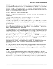
...when an assistant is listed on an incline. The recommended tire pressure is used to propel or lift the chair. Part No 1088909 11 Patriot™ Doing so may cause the tire to explode and cause bodily harm. DO NOT overtighten hardware attaching to and from the wheelchair.... (detachable) parts of a wheelchair may result in the upward position or swing footrests towards the outside of the wheelchair. DO NOT stand on this wheelchair (you may order with or without the handrims), Invacare strongly recommends ordering the handrims as the HANDRIMS are in injury to the user ...
...when an assistant is listed on an incline. The recommended tire pressure is used to propel or lift the chair. Part No 1088909 11 Patriot™ Doing so may cause the tire to explode and cause bodily harm. DO NOT overtighten hardware attaching to and from the wheelchair.... (detachable) parts of a wheelchair may result in the upward position or swing footrests towards the outside of the wheelchair. DO NOT stand on this wheelchair (you may order with or without the handrims), Invacare strongly recommends ordering the handrims as the HANDRIMS are in injury to the user ...
Owners Manual
Page 19
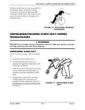
..., refer to create the longest possible wheelbase. Engage both wheel locks, open the footrest/legrest for clearance and transfer into the side frame H-blocks. FIGURE 2.6 - Grasp the push closest to you . 2. UNFOLDING SLING SEAT Part No 1088909 19 Patriot™ Push downward on page 17. Tilt the wheelchair towards you (raising the...
..., refer to create the longest possible wheelbase. Engage both wheel locks, open the footrest/legrest for clearance and transfer into the side frame H-blocks. FIGURE 2.6 - Grasp the push closest to you . 2. UNFOLDING SLING SEAT Part No 1088909 19 Patriot™ Push downward on page 17. Tilt the wheelchair towards you (raising the...
Owners Manual
Page 20
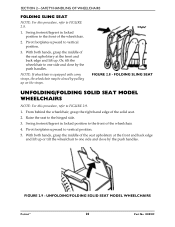
... If wheelchair is equipped with carry straps, the wheelchair may be closed by the push handles. Swing footrest/legrest in locked position to the front of the wheelchair. 4. Swing footrest/legrest in locked position to the front of the wheelchair. 2. FIGURE 2.8 - Or, tilt the ...wheelchair to one side and close by the push handles. Pivot footplates upward to FIGURE 2.8. 1. UNFOLDING/FOLDING SOLID SEAT MODEL WHEELCHAIRS Patriot™ 20 Part No ...
... If wheelchair is equipped with carry straps, the wheelchair may be closed by the push handles. Swing footrest/legrest in locked position to the front of the wheelchair. 4. Swing footrest/legrest in locked position to the front of the wheelchair. 2. FIGURE 2.8 - Or, tilt the ...wheelchair to one side and close by the push handles. Pivot footplates upward to FIGURE 2.8. 1. UNFOLDING/FOLDING SOLID SEAT MODEL WHEELCHAIRS Patriot™ 20 Part No ...
Owners Manual
Page 26
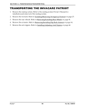
...; 26 Part No 1088909 SECTION 4-MAINTENANCE/TRANSPORTING TRANSPORTING THE INVACARE PATRIOT 1. Refer to Removing/Installing Flip Back Armrest on page 41. 4. Refer to Removing/Installing Rear Wheels on page 34. 5. Refer to Installing/Removing Swingaway Footrest on page 46. Remove the armrests. Remove the footrests. Refer to Installing/Adjusting Anti‐Tippers on page...
...; 26 Part No 1088909 SECTION 4-MAINTENANCE/TRANSPORTING TRANSPORTING THE INVACARE PATRIOT 1. Refer to Removing/Installing Flip Back Armrest on page 41. 4. Refer to Removing/Installing Rear Wheels on page 34. 5. Refer to Installing/Removing Swingaway Footrest on page 46. Remove the armrests. Remove the footrests. Refer to Installing/Adjusting Anti‐Tippers on page...
Owners Manual
Page 27
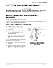
... the inside of the wheelchair frame. 3. Repeat STEPS 1‐3 for the other footrest assembly. 5. INSTALLING/ REMOVING SWINGAWAY FOOTREST Part No 1088909 27 Patriot™ Swingaway Footrest Assembly Mounting Pin Footrest Release Lever Mounting Tube FIGURE 5.1 - NOTE: 70° front riggings require the casters to be in place. 4. NOTE: The footplate will be performed by a qualified...
... the inside of the wheelchair frame. 3. Repeat STEPS 1‐3 for the other footrest assembly. 5. INSTALLING/ REMOVING SWINGAWAY FOOTREST Part No 1088909 27 Patriot™ Swingaway Footrest Assembly Mounting Pin Footrest Release Lever Mounting Tube FIGURE 5.1 - NOTE: 70° front riggings require the casters to be in place. 4. NOTE: The footplate will be performed by a qualified...

Owners Manual
Page 28
... out of the mounting pin of the wheelchair, if necessary. Remove the footrest from the footrest upper support. 3. Install the footrest assembly onto the wheelchair. Refer to Installing Heel Loops on page 27. 2. FIGURE 5.2 - Patriot™ 28 Part No 1088909 ADJUSTING SWINGAWAY FOOTREST HEIGHT 1. Install the new heel loop. Remove the hex screw and coved...
... out of the mounting pin of the wheelchair, if necessary. Remove the footrest from the footrest upper support. 3. Install the footrest assembly onto the wheelchair. Refer to Installing Heel Loops on page 27. 2. FIGURE 5.2 - Patriot™ 28 Part No 1088909 ADJUSTING SWINGAWAY FOOTREST HEIGHT 1. Install the new heel loop. Remove the hex screw and coved...

Owners Manual
Page 29
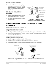
... FIGURE 5.3 - NOTE: The calfpad of the legrest will be installed to ensure the wheelchair locks in place. Part No 1088909 29 Patriot™ Position new heel loop over mounting tube. 2. INSTALLING ELEVATING LEGREST 1. Rotate legrest/calfpad assembly toward the inside of the wheelchair... secure it locks in place - Repeat STEPS 1‐3 for opposite side, if necessary. NOTE: When securing new heel loop to footrest assembly, tighten the mounting screw and locknut until it with the mounting screw, spacer and locknut. REMOVING/INSTALLING HEEL LOOPS INSTALLING/REMOVING ELEVATING...
... FIGURE 5.3 - NOTE: The calfpad of the legrest will be installed to ensure the wheelchair locks in place. Part No 1088909 29 Patriot™ Position new heel loop over mounting tube. 2. INSTALLING ELEVATING LEGREST 1. Rotate legrest/calfpad assembly toward the inside of the wheelchair... secure it locks in place - Repeat STEPS 1‐3 for opposite side, if necessary. NOTE: When securing new heel loop to footrest assembly, tighten the mounting screw and locknut until it with the mounting screw, spacer and locknut. REMOVING/INSTALLING HEEL LOOPS INSTALLING/REMOVING ELEVATING...
Owners Manual
Page 30
... refer to normal position, support leg with one hand and push release lever forward with other hand. ADJUSTING ELEVATING LEGREST/CALFPAD ASSEMBLY Patriot™ 30 Part No 1088909 SECTION 5-FRONT RIGGINGS 5. Release Lever Calf Pad Rotated For Height Adjustment Calf Pad FIGURE 5.5 -... Slide the calfpad up on the footplate assembly. 2. Push the legrest release handle inward while rotating the footrest outward. 2. Securely tighten bolt and nut. Mounting Tube Mounting Pin Legrest Release Handle Legrest Support Bolt and Nut Pivot Tube Footplate FIGURE...
... refer to normal position, support leg with one hand and push release lever forward with other hand. ADJUSTING ELEVATING LEGREST/CALFPAD ASSEMBLY Patriot™ 30 Part No 1088909 SECTION 5-FRONT RIGGINGS 5. Release Lever Calf Pad Rotated For Height Adjustment Calf Pad FIGURE 5.5 -... Slide the calfpad up on the footplate assembly. 2. Push the legrest release handle inward while rotating the footrest outward. 2. Securely tighten bolt and nut. Mounting Tube Mounting Pin Legrest Release Handle Legrest Support Bolt and Nut Pivot Tube Footplate FIGURE...
Owners Manual
Page 31
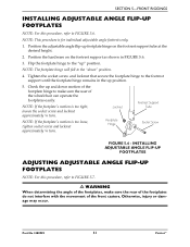
... Position the hardware on the footrest support tube at the desired height. 2. Flip the footplate hinge to the "up footplate hinge on the footrest support as shown in the up.... NOTE: If the footplateʹs motion is for individual adjustable angle footrests only. 1. Locknut Footplate Hinge Footrest Support Tube Socket Screw FIGURE 5.6 - INSTALLING ADJUSTABLE ANGLE FLIP-UP FOOTPLATES...FIGURE 5.6. Tighten the socket screw and locknut that secure the footplate hinge to the footrest support until the footplate hinge remains in FIGURE 5.6. 3. SECTION 5-FRONT RIGGINGS INSTALLING ...
... Position the hardware on the footrest support tube at the desired height. 2. Flip the footplate hinge to the "up footplate hinge on the footrest support as shown in the up.... NOTE: If the footplateʹs motion is for individual adjustable angle footrests only. 1. Locknut Footplate Hinge Footrest Support Tube Socket Screw FIGURE 5.6 - INSTALLING ADJUSTABLE ANGLE FLIP-UP FOOTPLATES...FIGURE 5.6. Tighten the socket screw and locknut that secure the footplate hinge to the footrest support until the footplate hinge remains in FIGURE 5.6. 3. SECTION 5-FRONT RIGGINGS INSTALLING ...
Owners Manual
Page 32
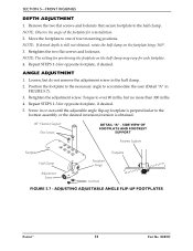
...desired. 5. Repeat STEPS 1‐3 for opposite footplate, if desired. Screw in the half clamp. 2. ADJUSTING ADJUSTABLE ANGLE FLIP-UP FOOTPLATES Patriot™ 32 Part No 1088909 NOTE: The setting for positioning the footplate on the footplate hinge 180°. 3. ANGLE ADJUSTMENT 1. SECTION ...obtained, rotate the half clamp on the half clamp may vary for reinstallation. 2. NOTE: If desired depth is obtained. 90° Footrest Support Flat Screws DETAIL "A" - Retighten the two flat screws and locknuts. Retighten the adjustment screw. Loosen, but no more than ...
...desired. 5. Repeat STEPS 1‐3 for opposite footplate, if desired. Screw in the half clamp. 2. ADJUSTING ADJUSTABLE ANGLE FLIP-UP FOOTPLATES Patriot™ 32 Part No 1088909 NOTE: The setting for positioning the footplate on the footplate hinge 180°. 3. ANGLE ADJUSTMENT 1. SECTION ...obtained, rotate the half clamp on the half clamp may vary for reinstallation. 2. NOTE: If desired depth is obtained. 90° Footrest Support Flat Screws DETAIL "A" - Retighten the two flat screws and locknuts. Retighten the adjustment screw. Loosen, but no more than ...