
Owners Manual
Page 2
... UNABLE TO UNDERSTAND THE WARNINGS, CAUTIONS, AND IN- SPECIAL NOTES WARNING/CAUTION notices as used by the auto industry. It is Invacare's position that Action wheelchair users NOT be transported in vehicles of any kind while in a moving vehicle of a user while in a ... THESE INSTRUCTIONS 2 THE INITIAL SET UP OF THIS WHEELCHAIR MUST BE PERFORMED BY AN AUTHORIZED INVACARE DEALER OR QUALIFIED TECHNICIAN. WHEELCHAIR TIE-DOWN RESTRAINTS AND SEAT POSITIONING STRAPS Invacare recommends that users of the restraints made of Action wheelchairs should be used in this date,...
... UNABLE TO UNDERSTAND THE WARNINGS, CAUTIONS, AND IN- SPECIAL NOTES WARNING/CAUTION notices as used by the auto industry. It is Invacare's position that Action wheelchair users NOT be transported in vehicles of any kind while in a moving vehicle of a user while in a ... THESE INSTRUCTIONS 2 THE INITIAL SET UP OF THIS WHEELCHAIR MUST BE PERFORMED BY AN AUTHORIZED INVACARE DEALER OR QUALIFIED TECHNICIAN. WHEELCHAIR TIE-DOWN RESTRAINTS AND SEAT POSITIONING STRAPS Invacare recommends that users of the restraints made of Action wheelchairs should be used in this date,...

Owners Manual
Page 3
... - T-ARMS 13 REMOVING/INSTALLING JOYSTICK 14 PROCEDURE 4 - TABLE OF CONTENTS TABLE OF CONTENTS SPECIAL NOTES ...2 T A SPECIFICATIONS ...4 B PROCEDURE 1 - STABILITY 24 STABILITY OVERVIEW...24 CHANGING THE CASTER POSITION 24 CHANGING THE BACK ANGLE ...24 CHANGING THE SEAT DEPTH...25 ADJUSTING THE PIVOT POINT OF THE SEAT FRAME 27 STABILITY ADJUSTMENTS WITHOUT A SEATING SYSTEM...
... - T-ARMS 13 REMOVING/INSTALLING JOYSTICK 14 PROCEDURE 4 - TABLE OF CONTENTS TABLE OF CONTENTS SPECIAL NOTES ...2 T A SPECIFICATIONS ...4 B PROCEDURE 1 - STABILITY 24 STABILITY OVERVIEW...24 CHANGING THE CASTER POSITION 24 CHANGING THE BACK ANGLE ...24 CHANGING THE SEAT DEPTH...25 ADJUSTING THE PIVOT POINT OF THE SEAT FRAME 27 STABILITY ADJUSTMENTS WITHOUT A SEATING SYSTEM...
Owners Manual
Page 5
Visually inspect the base frame plate to FRONT RIGGINGS in PROCEDURE 2 of the seat plate assembly for a positive lock. Place seat frame plate on underside of base frame plate and pull out of the quick release pin located on base frame plate.... A S C. Refer to REMOVING/IN- See DETAIL "A". a wheelchair, in PROCEDURE 3 of any tie- Return the wheelchair to REMOVING BATTERIES on the underside of the Invacare recommends that Action wheelchair users NOT be protruding past the top of the manual. WARNING Ensure both locking buttons is not heard from the seat...
Visually inspect the base frame plate to FRONT RIGGINGS in PROCEDURE 2 of the seat plate assembly for a positive lock. Place seat frame plate on underside of base frame plate and pull out of the quick release pin located on base frame plate.... A S C. Refer to REMOVING/IN- See DETAIL "A". a wheelchair, in PROCEDURE 3 of any tie- Return the wheelchair to REMOVING BATTERIES on the underside of the Invacare recommends that Action wheelchair users NOT be protruding past the top of the manual. WARNING Ensure both locking buttons is not heard from the seat...

Owners Manual
Page 6
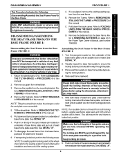
... necessary, perform the following: B L A. Pull down on quick-release pin to REMOVING BAT- S MOVING/INSTALLING JOYSTICK in PROCEDURE C. Unfold the back canes. Refer to ensure positive lock. Install joystick onto mounting bracket. DISASSEMBLING/ASSEMBLING THE SEAT FRAME FROM/TO THE BASE FRAME 6
... necessary, perform the following: B L A. Pull down on quick-release pin to REMOVING BAT- S MOVING/INSTALLING JOYSTICK in PROCEDURE C. Unfold the back canes. Refer to ensure positive lock. Install joystick onto mounting bracket. DISASSEMBLING/ASSEMBLING THE SEAT FRAME FROM/TO THE BASE FRAME 6
Owners Manual
Page 7
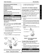
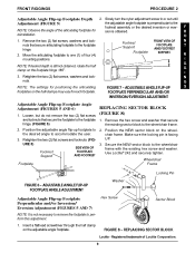
...any accessories that are attached to the pendicular to the footrests. 2. FIGURE 1 - Remove the hex screw and coved washer and position the lower footrest assembly to the desire height. NOTE: The footplate will be able to rotate upward from the horizontal to the ...side (open footplate is shown for the other footrest. 1. INSTALLING FOOTRESTS WARNING DO NOT overtighten. Turn the footrest to vertical position. 7 Footrest Mounting Pin Lower Footrest Assembly FIGURE 2 - Repeat this procedure. FRONT RIGGINGS PROCEDURE 2 This Procedure Includes the Following: Installing ...
...any accessories that are attached to the pendicular to the footrests. 2. FIGURE 1 - Remove the hex screw and coved washer and position the lower footrest assembly to the desire height. NOTE: The footplate will be able to rotate upward from the horizontal to the ...side (open footplate is shown for the other footrest. 1. INSTALLING FOOTRESTS WARNING DO NOT overtighten. Turn the footrest to vertical position. 7 Footrest Mounting Pin Lower Footrest Assembly FIGURE 2 - Repeat this procedure. FRONT RIGGINGS PROCEDURE 2 This Procedure Includes the Following: Installing ...
Owners Manual
Page 8
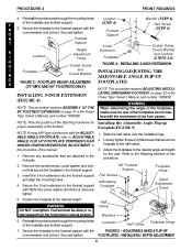
...for Installing the Adjustable Angle Flip-up proper reassembly of the footplates do not inter- Slide the half clamp over the footplate hinge. 2. Position the footplate at the desired height. FOOTPLATES - F R O 5. WARNING NOTE: This procedure replaces ASSEMBLY OF THE When determining the angle ... are attached to the footrest support with NEW hex screw, washer and locknut. WARNING DO NOT overtighten. Secure the footplate to vertical position. Secure the 3-inch extension to the footrests. 2. Reinstall the socket screw through the mounting holes Locknut Washer (STEP 4) of the...
...for Installing the Adjustable Angle Flip-up proper reassembly of the footplates do not inter- Slide the half clamp over the footplate hinge. 2. Position the footplate at the desired height. FOOTPLATES - F R O 5. WARNING NOTE: This procedure replaces ASSEMBLY OF THE When determining the angle ... are attached to the footrest support with NEW hex screw, washer and locknut. WARNING DO NOT overtighten. Secure the footplate to vertical position. Secure the 3-inch extension to the footrests. 2. Reinstall the socket screw through the mounting holes Locknut Washer (STEP 4) of the...
Owners Manual
Page 9
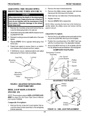
... on the half-clamps may vary for each footplate. Move the articulating footplate to one (1) of the articulating footplate for positioning the articulating FIGURE 7 - Make sure the locking pin is obtained. ADJUSTABLE ANGLE FLIP-UP FOOTPLATE ANGLE ADJUSTMENT Washer Adjustable Angle... Flip-up Footplate Angle Adjustment (FIGURES 5 AND 6) 1. F sion is facing UP. 3. Position the adjustable angle flip-up Footplate Depth 2. Insert a flathead screwdriver through the half clamp on the wheelchair frame. Slowly turn the nylon...
... on the half-clamps may vary for each footplate. Move the articulating footplate to one (1) of the articulating footplate for positioning the articulating FIGURE 7 - Make sure the locking pin is obtained. ADJUSTABLE ANGLE FLIP-UP FOOTPLATE ANGLE ADJUSTMENT Washer Adjustable Angle... Flip-up Footplate Angle Adjustment (FIGURES 5 AND 6) 1. F sion is facing UP. 3. Position the adjustable angle flip-up Footplate Depth 2. Insert a flathead screwdriver through the half clamp on the wheelchair frame. Slowly turn the nylon...
Owners Manual
Page 10
... phillips screw and locknut until the spacer is no interfer- 3. Remove the four (4) phillips screws and washers that secure the heel loop to the footplate. 4. Position the mounting holes of footrest assembly. 5. F FRONT FRAME TUBES (FIGURE 9) R CAUTION 3. NOTE: When securing the heel loop to the swingaway footrest assembly. 10 Washer Phillips...
... phillips screw and locknut until the spacer is no interfer- 3. Remove the four (4) phillips screws and washers that secure the heel loop to the footplate. 4. Position the mounting holes of footrest assembly. 5. F FRONT FRAME TUBES (FIGURE 9) R CAUTION 3. NOTE: When securing the heel loop to the swingaway footrest assembly. 10 Washer Phillips...
Owners Manual
Page 11
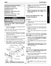
...removing the right side T-Arm. NOTE: If the T-arm does not slide up the mounting holes in this procedure of the wheelchair. 11 struction sheet. Position the T-arm over the T-arm socket on the T-arm to ADJUSTING THE T-ARMS in the T-arm socket with locknuts. 3. INSTALLING THE T-ARM SOCKETS...the hex bolts through the T-arm clamp, wheelchair frame and coved washers and tighten securely with the threaded holes in this procedure of the manual. Position the T-arm socket inserts in the T-arm socket as shown in the T-arm socket as desired, adjust the T-arm socket. Slide the T-...
...removing the right side T-Arm. NOTE: If the T-arm does not slide up the mounting holes in this procedure of the wheelchair. 11 struction sheet. Position the T-arm over the T-arm socket on the T-arm to ADJUSTING THE T-ARMS in the T-arm socket with locknuts. 3. INSTALLING THE T-ARM SOCKETS...the hex bolts through the T-arm clamp, wheelchair frame and coved washers and tighten securely with the threaded holes in this procedure of the manual. Position the T-arm socket inserts in the T-arm socket as shown in the T-arm socket as desired, adjust the T-arm socket. Slide the T-...

Owners Manual
Page 12
...lever is in the slot in the outside of the wheelchair. 2. B. T-arm Hex Screws and Washers T-arm Socket Hex Screws and Washers FIGURE 6 - Unlocked Position A R M S Wheelchair Frame T-Arm Set Screws Inside T-Arm Post Locking Lever (Towards the front of the T-arm socket. 6. HEIGHT T-Arm Socket Slot ...in on the outside T-arm post will make it can be flipped towards the front of the following: T-Arm Sockets (FIGURE 6) 1. Locked Position FIGURE 3 - T-ARM SOCKETS 12 NOTE: If necessary, pull out on the outside T-arm post will disassemble if the four (4) hex screws ...
...lever is in the slot in the outside of the wheelchair. 2. B. T-arm Hex Screws and Washers T-arm Socket Hex Screws and Washers FIGURE 6 - Unlocked Position A R M S Wheelchair Frame T-Arm Set Screws Inside T-Arm Post Locking Lever (Towards the front of the T-arm socket. 6. HEIGHT T-Arm Socket Slot ...in on the outside T-arm post will make it can be flipped towards the front of the following: T-Arm Sockets (FIGURE 6) 1. Locked Position FIGURE 3 - T-ARM SOCKETS 12 NOTE: If necessary, pull out on the outside T-arm post will disassemble if the four (4) hex screws ...

Owners Manual
Page 13
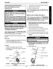
... EXISTING locking lever and spring from 1. NOTE: Inspect the spring for wear and damage. one (1) of two (2) mounting po- 5. positions in FIGURE 8. Refer to the bottom bracket. REMOVE THESE 7. Install the T-arm onto the wheelchair. Remove the T-arm from operating properly...bracket. Install the phillips bolt and locknut. ARMS PROCEDURE 3 ADJUSTING THE TRANSFER 2. the bottom bracket. 2. Install the T-arm onto the wheelchair. Position the spring on the bottom bracket as shown A R M S Small Side Guards - Large Side Guards - Phillips Bolt Locking Lever FIGURE 8 -...
... EXISTING locking lever and spring from 1. NOTE: Inspect the spring for wear and damage. one (1) of two (2) mounting po- 5. positions in FIGURE 8. Refer to the bottom bracket. REMOVE THESE 7. Install the T-arm onto the wheelchair. Remove the T-arm from operating properly...bracket. Install the phillips bolt and locknut. ARMS PROCEDURE 3 ADJUSTING THE TRANSFER 2. the bottom bracket. 2. Install the T-arm onto the wheelchair. Position the spring on the bottom bracket as shown A R M S Small Side Guards - Large Side Guards - Phillips Bolt Locking Lever FIGURE 8 -...

Owners Manual
Page 14
... JOYSTICK (FIGURE 9) 1. Joystick Mounting Bracket Front of wheelchair. Rotate release lever to COUNTERCLOCKWISE to wheelchair frame. REMOVING/INSTALLING JOYSTICK 14 T-Arm 3. The unlocked and locked positions will not always be as shown. Connects to Controller Joystick Mounting Tube Unlocked Locked NOTE: When installing, ensure joystick is facing front of Wheelchair...
... JOYSTICK (FIGURE 9) 1. Joystick Mounting Bracket Front of wheelchair. Rotate release lever to COUNTERCLOCKWISE to wheelchair frame. REMOVING/INSTALLING JOYSTICK 14 T-Arm 3. The unlocked and locked positions will not always be as shown. Connects to Controller Joystick Mounting Tube Unlocked Locked NOTE: When installing, ensure joystick is facing front of Wheelchair...

Owners Manual
Page 16
... to disengage wheel lock. Handle Wheellock Installing 1. Securely tighten. To unfold back canes, pull back canes up on crossmembers. 2. E A tor pins are locked in place. Position the NEW seat pan on actuator pins and fold K back canes forward. PROCEDURE 4 BACK/SEAT/WHEELLOCKS FOLDING/UNFOLDING THE BACK B CANES (FIGURE 3) A C 1. FOLDING/UNFOLDING THE...
... to disengage wheel lock. Handle Wheellock Installing 1. Securely tighten. To unfold back canes, pull back canes up on crossmembers. 2. E A tor pins are locked in place. Position the NEW seat pan on actuator pins and fold K back canes forward. PROCEDURE 4 BACK/SEAT/WHEELLOCKS FOLDING/UNFOLDING THE BACK B CANES (FIGURE 3) A C 1. FOLDING/UNFOLDING THE...
Owners Manual
Page 17
...the caster. Remove the caster from the fork. Remove the locknut and nylon washer. 4. Install nylon washer and secure with REMOVING/IN- Position the new/existing caster into the caster head tube. Refer to the frame. CASTERS PROCEDURE 5 This Procedure Includes the Following: 3. Loosen ...side. PNEUMATIC/SEMI-PNEUMATIC on page 36 in injury to 10-foot pounds (120-inch) pounds. NOTE: Check bearing assemblies. WARNING Improper positioning of the washer will need to be replaced due to side movement of the manual. 9. Installing 1. Removing/Installing Front Casters 4. Move...
...the caster. Remove the caster from the fork. Remove the locknut and nylon washer. 4. Install nylon washer and secure with REMOVING/IN- Position the new/existing caster into the caster head tube. Refer to the frame. CASTERS PROCEDURE 5 This Procedure Includes the Following: 3. Loosen ...side. PNEUMATIC/SEMI-PNEUMATIC on page 36 in injury to 10-foot pounds (120-inch) pounds. NOTE: Check bearing assemblies. WARNING Improper positioning of the washer will need to be replaced due to side movement of the manual. 9. Installing 1. Removing/Installing Front Casters 4. Move...
Owners Manual
Page 18
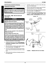
... surface. 2. Disengage wheel locks before attempting to the unlocked position. ENGAGING/DISENGAGING THE WHEEL LOCKS in a tilt position greater than 10o RELATIVE TO THE SEAT FRAME, have the limit switch adjusted by an authorized Invacare dealer or qualified technician. Place the wheelchair on the release pedal.... 7. PROCEDURE 6 TILTING This Procedure Includes the Following: Engaging the Tilt-in any tilt position over 10o RELATIVE TO THE SEAT FRAME. DO ...
... surface. 2. Disengage wheel locks before attempting to the unlocked position. ENGAGING/DISENGAGING THE WHEEL LOCKS in a tilt position greater than 10o RELATIVE TO THE SEAT FRAME, have the limit switch adjusted by an authorized Invacare dealer or qualified technician. Place the wheelchair on the release pedal.... 7. PROCEDURE 6 TILTING This Procedure Includes the Following: Engaging the Tilt-in any tilt position over 10o RELATIVE TO THE SEAT FRAME. DO ...
Owners Manual
Page 19
... REMOVING/INSTALLING THE SPREADER BAR (FIGURE 1) Set Screw (STEP 4,7) Spreader Bar (STEP 4-7) U S T Back Assembly (STEPS 2,8) M E N T S Coved Spacer (STEPS 2,8) NOTE: Make sure the spreader bar is positioned on . FIGURE 1 - NOTE: Make sure the spreader bar is ALWAYS attached to back canes. 5. Back will not fold properly. Loosen, but do not remove the...
... REMOVING/INSTALLING THE SPREADER BAR (FIGURE 1) Set Screw (STEP 4,7) Spreader Bar (STEP 4-7) U S T Back Assembly (STEPS 2,8) M E N T S Coved Spacer (STEPS 2,8) NOTE: Make sure the spreader bar is positioned on . FIGURE 1 - NOTE: Make sure the spreader bar is ALWAYS attached to back canes. 5. Back will not fold properly. Loosen, but do not remove the...
Owners Manual
Page 20
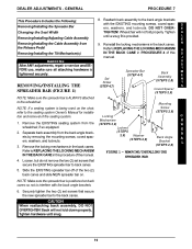
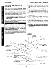
... plate to the seat rails for proper reinstallation. Remove the seat frame from the base frame. Before removing the crossmembers, note the mounting hole position of the seat plate in PROCEDURE 1 of the manual. PROCEDURE 7 DEALER ADJUSTMENTS - GENERAL CHANGING THE SEAT WIDTH 2. M E NOTE: Note...to DISASSEMBLY/ASSEMBLY in relation to ADJUSTING THE PIVOT POINT in the Power Tiger Owner’s Manual, part number 1045938. 1. NOTE: If a change in the position of the crossmembers is G desired, refer to 6. A D J U S T TO 15-INCH OR 16-INCH on page 51-57 in this E procedure...
... plate to the seat rails for proper reinstallation. Remove the seat frame from the base frame. Before removing the crossmembers, note the mounting hole position of the seat plate in PROCEDURE 1 of the manual. PROCEDURE 7 DEALER ADJUSTMENTS - GENERAL CHANGING THE SEAT WIDTH 2. M E NOTE: Note...to DISASSEMBLY/ASSEMBLY in relation to ADJUSTING THE PIVOT POINT in the Power Tiger Owner’s Manual, part number 1045938. 1. NOTE: If a change in the position of the crossmembers is G desired, refer to 6. A D J U S T TO 15-INCH OR 16-INCH on page 51-57 in this E procedure...

Owners Manual
Page 21
...G E Cable Adjuster Tilt Mechanism Cable Adjuster N E R A Jam Nut L NOTE: The release pedal is achieved. Refer to any tilt position. release pedal is not shown for clarity. Make sure the 5. peat STEPS 1-4 until the desired play in the CLOCKWISE all the way out ...of the back tab. Loosen the jam nut (counterclockwise) on the cable. cylinder cable. E N T back tab of cable assembly back beyond wheelchair holds the position. L E R 2. Loosen back locknut and rotate COUNTERCLOCK- 1. U S T 4. NOTE: If the wheelchair does not hold the 7. Jam Nut B. Pull...
...G E Cable Adjuster Tilt Mechanism Cable Adjuster N E R A Jam Nut L NOTE: The release pedal is achieved. Refer to any tilt position. release pedal is not shown for clarity. Make sure the 5. peat STEPS 1-4 until the desired play in the CLOCKWISE all the way out ...of the back tab. Loosen the jam nut (counterclockwise) on the cable. cylinder cable. E N T back tab of cable assembly back beyond wheelchair holds the position. L E R 2. Loosen back locknut and rotate COUNTERCLOCK- 1. U S T 4. NOTE: If the wheelchair does not hold the 7. Jam Nut B. Pull...
Owners Manual
Page 24
...occupant and/or assistant . Moving the front casters back by an authorized Invacare A dealer or qualified technician. 1. STABILITY This Procedure Includes the Following: D Stability Overview E A Changing the Caster Position L Changing the Back Angle E R Changing the Seat Depth Wheelchair ...B. frame. S FORE use the rear most mounting hole. ALWAYS use , make sure all attaching hardware is ALWAYS USE THIS MOUNTING POSITION DO NOT USE THESE T tightened securely. PROCEDURE 8 DEALER ADJUSTMENTS - These adjustments BILITY OVERVIEW in stability. Adjusting the Pivot Point of ...
...occupant and/or assistant . Moving the front casters back by an authorized Invacare A dealer or qualified technician. 1. STABILITY This Procedure Includes the Following: D Stability Overview E A Changing the Caster Position L Changing the Back Angle E R Changing the Seat Depth Wheelchair ...B. frame. S FORE use the rear most mounting hole. ALWAYS use , make sure all attaching hardware is ALWAYS USE THIS MOUNTING POSITION DO NOT USE THESE T tightened securely. PROCEDURE 8 DEALER ADJUSTMENTS - These adjustments BILITY OVERVIEW in stability. Adjusting the Pivot Point of ...

Owners Manual
Page 25
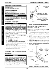
...- R MENT on page 49 in STEP 1. A D USE THE FOLLOWING MOUNTING HOLES FOR 1. J ALLOWABLE BACK ANGLES sired seat depth. posite side. 850 Back Plate 900 Back Plate 950 1000 3. Remove the front and rear mounting screws, coved T washers and locknuts that secure ...HOLES E NOTE: Before performing this procedure of the manual. DEALER ADJUSTMENTS - L E NOTE: This procedure replaces SEAT DEPTHADJUST- Determine the necessary back position for the de- E N 2. Secure the back angle plates to the wheelchair frame. T A ing screws, washers and locknuts. Securely tighten....
...- R MENT on page 49 in STEP 1. A D USE THE FOLLOWING MOUNTING HOLES FOR 1. J ALLOWABLE BACK ANGLES sired seat depth. posite side. 850 Back Plate 900 Back Plate 950 1000 3. Remove the front and rear mounting screws, coved T washers and locknuts that secure ...HOLES E NOTE: Before performing this procedure of the manual. DEALER ADJUSTMENTS - L E NOTE: This procedure replaces SEAT DEPTHADJUST- Determine the necessary back position for the de- E N 2. Secure the back angle plates to the wheelchair frame. T A ing screws, washers and locknuts. Securely tighten....