

Owners Manual
Page 1
ORBIT SEAT OPTION ON POWER TIGER BASE OWNER'S OPERATOR AND MAINTENANCE MANUAL
ORBIT SEAT OPTION ON POWER TIGER BASE OWNER'S OPERATOR AND MAINTENANCE MANUAL
Owners Manual
Page 2
... EVENT OF A FALL FROM A WHEELCHAIR. SAVE THESE INSTRUCTIONS 2 ALL PROCEDURES IN THIS MANUAL SUPERCEDE ANY DUPLICATED PROCEDURES FOUND IN THE POWER TIGER OWNER'S MANUAL, PART NUMBER 1045938. WHEELCHAIR TIE-DOWN RESTRAINTS AND SEAT POSITIONING STRAPS Invacare recommends that users of wheelchair to meet many needs of a user while in a wheelchair, in personal injury or property damage. It is Invacare's position that Action wheelchair users NOT be made of...
... EVENT OF A FALL FROM A WHEELCHAIR. SAVE THESE INSTRUCTIONS 2 ALL PROCEDURES IN THIS MANUAL SUPERCEDE ANY DUPLICATED PROCEDURES FOUND IN THE POWER TIGER OWNER'S MANUAL, PART NUMBER 1045938. WHEELCHAIR TIE-DOWN RESTRAINTS AND SEAT POSITIONING STRAPS Invacare recommends that users of wheelchair to meet many needs of a user while in a wheelchair, in personal injury or property damage. It is Invacare's position that Action wheelchair users NOT be made of...

Owners Manual
Page 4
Low Mounted Weight (Approx.) W/O Batteries: With Batteries: 95 lbs. 173 lbs. SPECIFICATIONS SPECIFICATIONS PHYSICAL SPECIFICATIONS S P Overall Width: E C I Overall Depth (w/o front riggings): F Overall Height: I C Seat Width: A Seat Depth: T I Seat-to-Floor Height: O Back Style and Height: N S Arm Styles: ORBIT SEAT OPTION ON POWER TIGER BASE *23-inches (including joystick) *30-inches *41-inches 10 to 16-inches (in one {1} inch increments) 10 to 16...
Low Mounted Weight (Approx.) W/O Batteries: With Batteries: 95 lbs. 173 lbs. SPECIFICATIONS SPECIFICATIONS PHYSICAL SPECIFICATIONS S P Overall Width: E C I Overall Depth (w/o front riggings): F Overall Height: I C Seat Width: A Seat Depth: T I Seat-to-Floor Height: O Back Style and Height: N S Arm Styles: ORBIT SEAT OPTION ON POWER TIGER BASE *23-inches (including joystick) *30-inches *41-inches 10 to 16-inches (in one {1} inch increments) 10 to 16...
Owners Manual
Page 5
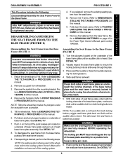
... the wheelchair, refer to REMOVING BATTERIES on underside of S this manual. DISASSEMBLY/ASSEMBLY PROCEDURE 1 This Procedure Includes the Following: A. I WARNING After ANY adjustments, repair or service and BEFORE use, make sure all the way through the plate. STALLING THE T-ARMS in 3. B DISASSEMBLING/ASSEMBLING THE SEAT FRAME FROM/TO THE BASE FRAME (FIGURE 1) D. L Y fer to the seating system Owner's Manual for installation and...
... the wheelchair, refer to REMOVING BATTERIES on underside of S this manual. DISASSEMBLY/ASSEMBLY PROCEDURE 1 This Procedure Includes the Following: A. I WARNING After ANY adjustments, repair or service and BEFORE use, make sure all the way through the plate. STALLING THE T-ARMS in 3. B DISASSEMBLING/ASSEMBLING THE SEAT FRAME FROM/TO THE BASE FRAME (FIGURE 1) D. L Y fer to the seating system Owner's Manual for installation and...

Owners Manual
Page 6
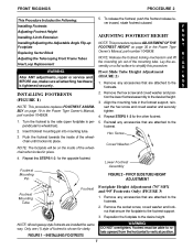
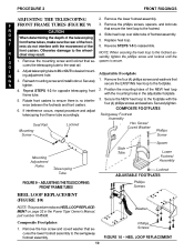
... Locking Buttons Seat Frame Plate Base Frame Plate SEAT FRAME BASE FRAME SECTIONAL OF SEAT FRAME AND BASE FRAME ASSEMBLED (WITHOUT SEATING SYSTEM) DETAIL "A" - Refer to ensure positive lock. Unfold the back canes. Refer to the seating system Owner's Manual for in- chair, refer to FRONT RIGGINGS in STALLING THE T-ARMS in the Power Tiger Owner’s Manual, part number 1045938. PROCEDURE 1 DISASSEMBLY/ASSEMBLY 7. Install the footrests. Refer...
... Locking Buttons Seat Frame Plate Base Frame Plate SEAT FRAME BASE FRAME SECTIONAL OF SEAT FRAME AND BASE FRAME ASSEMBLED (WITHOUT SEATING SYSTEM) DETAIL "A" - Refer to ensure positive lock. Unfold the back canes. Refer to the seating system Owner's Manual for in- chair, refer to FRONT RIGGINGS in STALLING THE T-ARMS in the Power Tiger Owner’s Manual, part number 1045938. PROCEDURE 1 DISASSEMBLY/ASSEMBLY 7. Install the footrests. Refer...
Owners Manual
Page 7
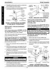
... the footrest to the footrests. Push the footrest towards the inside of footrest is tightened securely. 1. Hex Screw Coved Washer 4. Remove the socket screw, coved washer and locknut that are installed the same way. Only one (1) style of the wheelchair when locked in the Power Tiger Owner’s Manual, part number 1045938. 2. FIGURE 1 - Footrest must be on page 30 in the footrest support, reinsert...
... the footrest to the footrests. Push the footrest towards the inside of footrest is tightened securely. 1. Hex Screw Coved Washer 4. Remove the socket screw, coved washer and locknut that are installed the same way. Only one (1) style of the wheelchair when locked in the Power Tiger Owner’s Manual, part number 1045938. 2. FIGURE 1 - Footrest must be on page 30 in the footrest support, reinsert...
Owners Manual
Page 8
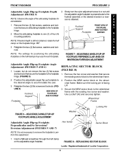
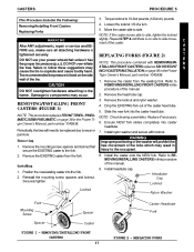
... replaces ASSEMBLY OF THE When determining the angle of the footplates, 90o FOOTREST EXTENSION on page 32 in the Power Tiger Owner’s Manual, part number 1045938. Remove any accessories that secure the footplate to the footrest support.... Refer to the footrest support with the coved washer and locknut. Footrest must be able to rotate upward from the horizontal to the half clamp. 3. N Footrest T Support (STEP 4) Footrest Support 3-inch Hex Screw (STEP 4) Socket Screw, R I Footplate N and Coved Washer INSTALLING/ADJUSTING THE ADJUSTABLE ANGLE...
... replaces ASSEMBLY OF THE When determining the angle of the footplates, 90o FOOTREST EXTENSION on page 32 in the Power Tiger Owner’s Manual, part number 1045938. Remove any accessories that secure the footplate to the footrest support.... Refer to the footrest support with the coved washer and locknut. Footrest must be able to rotate upward from the horizontal to the half clamp. 3. N Footrest T Support (STEP 4) Footrest Support 3-inch Hex Screw (STEP 4) Socket Screw, R I Footplate N and Coved Washer INSTALLING/ADJUSTING THE ADJUSTABLE ANGLE...
Owners Manual
Page 9
... and locknuts that secure articulating footplate to the wheelchair frame with the existing hex screw and washer. Footrest Support FRONT VIEW OF N FOOTPLATE T AND FOOTREST Footplate SUPPORT. FOOTPLATE PERPENDICULAR AND/OR INVERSION/EVERSION ADJUSTMENT Adjustable Angle Flip-up Footplate Depth 2. URE 5) SIDE VIEW OF Footrest FOOTPLATE Support AND FOOTREST Footplate REPLACING SECTOR BLOCK (FIGURE 8) 1. Secure the NEW sector block...
... and locknuts that secure articulating footplate to the wheelchair frame with the existing hex screw and washer. Footrest Support FRONT VIEW OF N FOOTPLATE T AND FOOTREST Footplate SUPPORT. FOOTPLATE PERPENDICULAR AND/OR INVERSION/EVERSION ADJUSTMENT Adjustable Angle Flip-up Footplate Depth 2. URE 5) SIDE VIEW OF Footrest FOOTPLATE Support AND FOOTREST Footplate REPLACING SECTOR BLOCK (FIGURE 8) 1. Secure the NEW sector block...
Owners Manual
Page 10
... adjustment hole. Reinsert mounting screw and install locknut. Secure the NEW heel loop to the footplate with the movement of the footrests do not interfere with the ence between the footrests and front casters. If interference occurs,...- 3. with the mounting holes in the Power Tiger Owner’s Manual, part number 1045938. Securely tighten. 6. F FRONT FRAME TUBES (FIGURE 9) R CAUTION 3. Rotate front casters to the footrest. R I N 2. Otherwise damage to the seat rail. Composite Footplates 1. Remove the mounting ...
... adjustment hole. Reinsert mounting screw and install locknut. Secure the NEW heel loop to the footplate with the movement of the footrests do not interfere with the ence between the footrests and front casters. If interference occurs,...- 3. with the mounting holes in the Power Tiger Owner’s Manual, part number 1045938. Securely tighten. 6. F FRONT FRAME TUBES (FIGURE 9) R CAUTION 3. Rotate front casters to the footrest. R I N 2. Otherwise damage to the seat rail. Composite Footplates 1. Remove the mounting ...
Owners Manual
Page 11
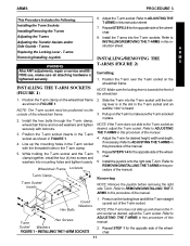
...the T-arm socket. INSTALLING THE T-ARM SOCKETS 1. A Replacing the Locking Lever - T-arms R Removing/Installing Joystick WARNING INSTALLING/REMOVING THE M T-ARMS (FIGURE 2) S After ANY adjustments, repair or service and BEFORE use, make sure the T-arm is Installing tightened securely. 1. While...wheelchair frame. 2. Adjust the T-arm for the opposite side of the wheelchair. 6. Refer to ADJUSTING THE T-ARMS in this instruction sheet. 7. Repeat STEP 1 for the opposite side of the wheelchair. 11 T-arms INSTALLING/REMOVING THE T-ARMS in this procedure of the manual...
...the T-arm socket. INSTALLING THE T-ARM SOCKETS 1. A Replacing the Locking Lever - T-arms R Removing/Installing Joystick WARNING INSTALLING/REMOVING THE M T-ARMS (FIGURE 2) S After ANY adjustments, repair or service and BEFORE use, make sure the T-arm is Installing tightened securely. 1. While...wheelchair frame. 2. Adjust the T-arm for the opposite side of the wheelchair. 6. Refer to ADJUSTING THE T-ARMS in this instruction sheet. 7. Repeat STEP 1 for the opposite side of the wheelchair. 11 T-arms INSTALLING/REMOVING THE T-ARMS in this procedure of the manual...

Owners Manual
Page 15
... toward seat rails. 6. Make sure the angled end of the manual. 2. Quick-Release Pin FIGURE 2 - Slowly remove the back canes from the wheelchair to remove from the locking mechanism. Twist the actuator COUNTERCLOCKWISE to prevent the springs from (FIGURE 1) both back canes. Unfold back canes. Replace if necessary. REPLACING THE LOCKING E After ANY adjustments, repair or service...
... toward seat rails. 6. Make sure the angled end of the manual. 2. Quick-Release Pin FIGURE 2 - Slowly remove the back canes from the wheelchair to remove from the locking mechanism. Twist the actuator COUNTERCLOCKWISE to prevent the springs from (FIGURE 1) both back canes. Unfold back canes. Replace if necessary. REPLACING THE LOCKING E After ANY adjustments, repair or service...

Owners Manual
Page 16
.... Handle Wheellock Installing 1. Rigid Seat Pan Mounting Screws S 2. Push handle forward away from wheelchair. 2. If so equipped, remove seating system from tire to your particular seating system manufacturer's Owner's Manual for installation and removal of the seating system. 1. Secure with the existing four (4) mounting screws. T NOTE: Actuator pins are locked in place when an au- ENGAGING/DISENGAGING THE WHEEL LOCKS 3.
.... Handle Wheellock Installing 1. Rigid Seat Pan Mounting Screws S 2. Push handle forward away from wheelchair. 2. If so equipped, remove seating system from tire to your particular seating system manufacturer's Owner's Manual for installation and removal of the seating system. 1. Secure with the existing four (4) mounting screws. T NOTE: Actuator pins are locked in place when an au- ENGAGING/DISENGAGING THE WHEEL LOCKS 3.
Owners Manual
Page 17
...hardware is no side to side movement of the washer will need to be replaced due to REMOVING/INSTALLING FRONT CASTERS in the Power Therecommendedtirepressureislistedontheside Tiger Owner’s Manual, part number 1045938. DO NOT over-inflate NOTE: This procedure combined with locknut. CAUTION...PROCEDURE 5 This Procedure Includes the Following: 3. INCH CASTER INSTALLATION on page 38 in injury to the fork. 3. Installing 1. Damage to side, tighten the locknut WARNING After ANY adjustments, repair or service and BE- Remove the mounting screw, spacers and locknut that...
...hardware is no side to side movement of the washer will need to be replaced due to REMOVING/INSTALLING FRONT CASTERS in the Power Therecommendedtirepressureislistedontheside Tiger Owner’s Manual, part number 1045938. DO NOT over-inflate NOTE: This procedure combined with locknut. CAUTION...PROCEDURE 5 This Procedure Includes the Following: 3. INCH CASTER INSTALLATION on page 38 in injury to the fork. 3. Installing 1. Damage to side, tighten the locknut WARNING After ANY adjustments, repair or service and BE- Remove the mounting screw, spacers and locknut that...
Owners Manual
Page 18
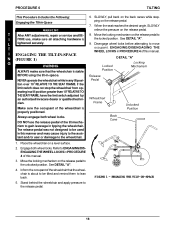
.... 7. See DETAIL "A". Disengage wheel locks before attempting to the release pedal. NEVER operate the wheelchair while in a tilt position greater than 10o RELATIVE TO THE SEAT FRAME, have the limit switch adjusted by an authorized Invacare dealer or qualified technician. DO NOT use , make sure that the wheelchair is stable Position BEFORE using the tilt-in this...
.... 7. See DETAIL "A". Disengage wheel locks before attempting to the release pedal. NEVER operate the wheelchair while in a tilt position greater than 10o RELATIVE TO THE SEAT FRAME, have the limit switch adjusted by an authorized Invacare dealer or qualified technician. DO NOT use , make sure that the wheelchair is stable Position BEFORE using the tilt-in this...
Owners Manual
Page 19
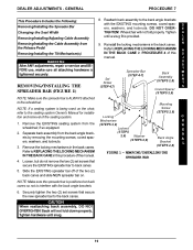
...seating system is being used on the chair, refer to the seating system Owner's Manual for installation and removal of the two (2) back canes and slide NEW spreader bar on back canes so not to back canes. 5. Separate back assembly from the wheelchair, if so equipped. 2. Slide the EXISTING spreader bar off of the seating...back canes. REMOVING/INSTALLING THE SPREADER BAR 4. Reinstall the locking mechanisms in the back canes. J WARNING After ANY adjustments, repair or service and BEFORE use, make sure all attaching hardware is provided. Remove the EXISTING seating system from the ...
...seating system is being used on the chair, refer to the seating system Owner's Manual for installation and removal of the two (2) back canes and slide NEW spreader bar on back canes so not to back canes. 5. Separate back assembly from the wheelchair, if so equipped. 2. Slide the EXISTING spreader bar off of the seating...back canes. REMOVING/INSTALLING THE SPREADER BAR 4. Reinstall the locking mechanisms in the back canes. J WARNING After ANY adjustments, repair or service and BEFORE use, make sure all attaching hardware is provided. Remove the EXISTING seating system from the ...
Owners Manual
Page 20
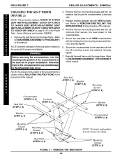
... DISASSEMBLY/ASSEMBLY in PROCEDURE 1 of the seat plate in the Power Tiger Owner’s Manual, part number 1045938. 1. PROCEDURE 7 DEALER ADJUSTMENTS - M E NOTE: Note the orientation of this manual. four (4) mounting screws and washers. injury to the occupant and/or user and damage to 6. Seat Rail N (STEP 2, 6) Washer E (STEP 2, 6) R A L Mounting Screws (STEP 2, 6) Crossmember (STEPS 2, 6) Seat Rail (STEP 2, 6) Locknuts (STEP 4, 5) Washer (STEP...
... DISASSEMBLY/ASSEMBLY in PROCEDURE 1 of the seat plate in the Power Tiger Owner’s Manual, part number 1045938. 1. PROCEDURE 7 DEALER ADJUSTMENTS - M E NOTE: Note the orientation of this manual. four (4) mounting screws and washers. injury to the occupant and/or user and damage to 6. Seat Rail N (STEP 2, 6) Washer E (STEP 2, 6) R A L Mounting Screws (STEP 2, 6) Crossmember (STEPS 2, 6) Seat Rail (STEP 2, 6) Locknuts (STEP 4, 5) Washer (STEP...
Owners Manual
Page 24
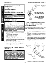
... decrease in stability which may cause the wheel- T Y B. Adjusting the Pivot Point of the wheelchair. Moving the front casters back by using the forward positions causes the wheelchair to the wheelchair 1. Wheelchair Frame Locknut Washer Coved Washers FIGURE 2 - CHANGING THE CASTER POSITION frame, seating system, caster position, as well as the user condition directly relate to determine the...
... decrease in stability which may cause the wheel- T Y B. Adjusting the Pivot Point of the wheelchair. Moving the front casters back by using the forward positions causes the wheelchair to the wheelchair 1. Wheelchair Frame Locknut Washer Coved Washers FIGURE 2 - CHANGING THE CASTER POSITION frame, seating system, caster position, as well as the user condition directly relate to determine the...

Owners Manual
Page 25
... manual. J ALLOWABLE BACK ANGLES sired seat depth. E N 2. posite side. 850 Back Plate 900 Back Plate 950 1000 3. Secure the back angle plates to STA- Securely tighten. DEALER ADJUSTMENTS - A BILITY OVERVIEW in the Power Tiger Owner’s Manual, part number 1045938. R MENT on page 49 in this procedure, refer to the wheelchair frame, at the I same angle BEFORE using the wheelchair...
... manual. J ALLOWABLE BACK ANGLES sired seat depth. E N 2. posite side. 850 Back Plate 900 Back Plate 950 1000 3. Secure the back angle plates to STA- Securely tighten. DEALER ADJUSTMENTS - A BILITY OVERVIEW in the Power Tiger Owner’s Manual, part number 1045938. R MENT on page 49 in this procedure, refer to the wheelchair frame, at the I same angle BEFORE using the wheelchair...
Owners Manual
Page 35
... TO PROBLEMS ARISING FROM NORMAL WEAR OR FAILURE TO ADHERE TO THESE INSTRUCTIONS. In the event you purchased your Invacare product. Invacare’s sole obligation and your particular Seating System Owner's Manual for a period of A one (1) year from whom you do not receive satisfactory warranty service, please write directly to such repair and/or replacement. Refer to state. Any seating system installed...
... TO PROBLEMS ARISING FROM NORMAL WEAR OR FAILURE TO ADHERE TO THESE INSTRUCTIONS. In the event you purchased your Invacare product. Invacare’s sole obligation and your particular Seating System Owner's Manual for a period of A one (1) year from whom you do not receive satisfactory warranty service, please write directly to such repair and/or replacement. Refer to state. Any seating system installed...

Owners Manual
Page 36
INVACARE CORPORATION l 39350 Taylor Parkway l North Ridgeville, OH 44039 Customer Service (800) 333-6900 l Technical Support (800) 832-4707 Form No. 98-303 Part No. 1083067 REV B (2) - 6/99 Printed in U.S.A.
INVACARE CORPORATION l 39350 Taylor Parkway l North Ridgeville, OH 44039 Customer Service (800) 333-6900 l Technical Support (800) 832-4707 Form No. 98-303 Part No. 1083067 REV B (2) - 6/99 Printed in U.S.A.


