
Owners Manual
Page 2
...IN THIS MANUAL SUPERCEDE ANY DUPLICATED PROCEDURES FOUND IN THE POWER TIGER OWNER'S MANUAL, PART NUMBER 1045938. THE INITIAL SET UP OF THIS WHEELCHAIR MUST BE PERFORMED BY AN AUTHORIZED INVACARE DEALER OR QUALIFIED TECHNICIAN. SERIOUS INJURY CAN OCCUR IN THE EVENT OF A FALL FROM...READING AND UNDERSTANDING THE INFORMATION IN THIS W A SUPPLEMENTAL MANUAL AND THE OWNER'S MANUAL. WHEELCHAIR USER As a manufacturer of wheelchairs, Invacare endeavors to supply a wide variety of Action wheelchairs to hazards or unsafe practices which could result in vehicles for transportation of a user...
...IN THIS MANUAL SUPERCEDE ANY DUPLICATED PROCEDURES FOUND IN THE POWER TIGER OWNER'S MANUAL, PART NUMBER 1045938. THE INITIAL SET UP OF THIS WHEELCHAIR MUST BE PERFORMED BY AN AUTHORIZED INVACARE DEALER OR QUALIFIED TECHNICIAN. SERIOUS INJURY CAN OCCUR IN THE EVENT OF A FALL FROM...READING AND UNDERSTANDING THE INFORMATION IN THIS W A SUPPLEMENTAL MANUAL AND THE OWNER'S MANUAL. WHEELCHAIR USER As a manufacturer of wheelchairs, Invacare endeavors to supply a wide variety of Action wheelchairs to hazards or unsafe practices which could result in vehicles for transportation of a user...
Owners Manual
Page 5
STALLING THE T-ARMS in A the Power Tiger Owner’s Manual, part number S 1045938. Refer to FOLDING/ S UNFOLDING THE BACK CANES in - B DISASSEMBLING/ASSEMBLING THE SEAT FRAME FROM/TO THE BASE FRAME (FIGURE 1) D. S E M Disassembling the Seat Frame from ... 6 of the manual. Push in on the tip of the quick release pin located on the underside of this manual. 6. See DETAIL "A". 8. E M DURE 4 of the Invacare recommends that Action wheelchair users NOT be protruding past the top of the base frame 3. Refer to ensure the ment of the quick-release pin...
STALLING THE T-ARMS in A the Power Tiger Owner’s Manual, part number S 1045938. Refer to FOLDING/ S UNFOLDING THE BACK CANES in - B DISASSEMBLING/ASSEMBLING THE SEAT FRAME FROM/TO THE BASE FRAME (FIGURE 1) D. S E M Disassembling the Seat Frame from ... 6 of the manual. Push in on the tip of the quick release pin located on the underside of this manual. 6. See DETAIL "A". 8. E M DURE 4 of the Invacare recommends that Action wheelchair users NOT be protruding past the top of the base frame 3. Refer to ensure the ment of the quick-release pin...

Owners Manual
Page 6
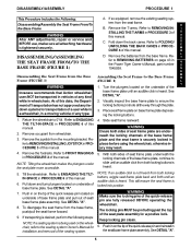
... to ensure positive lock. S E DURE 3 of this manual. If necessary, perform the following: B L A. Y FOLDING THE BACK CANES in the Power Tiger Owner’s Manual, part number 1045938. A 4 of this manual. S E M Locking Buttons B Engage Here SEAT FRAME AND BASE FRAME DISASSEMBLED L Y Locking Channel Locking Buttons Seat Frame Plate Base Frame Plate SEAT...
... to ensure positive lock. S E DURE 3 of this manual. If necessary, perform the following: B L A. Y FOLDING THE BACK CANES in the Power Tiger Owner’s Manual, part number 1045938. A 4 of this manual. S E M Locking Buttons B Engage Here SEAT FRAME AND BASE FRAME DISASSEMBLED L Y Locking Channel Locking Buttons Seat Frame Plate Base Frame Plate SEAT...
Owners Manual
Page 7
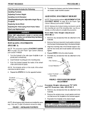
...INSTALLING FOOTRESTS (FIGURE 1) NOTE: This procedure replaces FOOTREST ASSEMBLY on page 30 in the Power Tiger Owner’s Manual, part number 1045938. 2. Reinstall any accessories that secure the footplate to the side (open footplate is tightened securely. 1. Repeat this procedure...replaces ADJUSTMENT OF THE FOOTREST HEIGHT on page 19 in the Power Tiger T Replacing Sector Block Owner’s Manual, part number 1045938. INSTALLING FOOTRESTS WARNING DO NOT overtighten. Remove any accessories that are attached to the footrests. 2. Remove any accessories ...
...INSTALLING FOOTRESTS (FIGURE 1) NOTE: This procedure replaces FOOTREST ASSEMBLY on page 30 in the Power Tiger Owner’s Manual, part number 1045938. 2. Reinstall any accessories that secure the footplate to the side (open footplate is tightened securely. 1. Repeat this procedure...replaces ADJUSTMENT OF THE FOOTREST HEIGHT on page 19 in the Power Tiger T Replacing Sector Block Owner’s Manual, part number 1045938. INSTALLING FOOTRESTS WARNING DO NOT overtighten. Remove any accessories that are attached to the footrests. 2. Remove any accessories ...
Owners Manual
Page 8
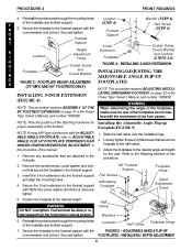
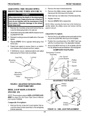
... the FIGURE 5 - INSTALLING 3-INCH EXTENSION (FIGURE 4) LATING SWINGAWAY FOOTREST on page 31 in the Power Tiger Owner’s Manual, part number 1045938. Insert the 3-inch extension into the footrest support and align the mounting holes. 4. Position the footplate at the desired height. ADJUSTABLE... ANGLE FLIP-UP coved washer and locknut. Tiger Owner’s Manual, part number 1045938. Remove any accessories that secure the footplate to the following sections of this procedure of the footplates do not inter- Remove ...
... the FIGURE 5 - INSTALLING 3-INCH EXTENSION (FIGURE 4) LATING SWINGAWAY FOOTREST on page 31 in the Power Tiger Owner’s Manual, part number 1045938. Insert the 3-inch extension into the footrest support and align the mounting holes. 4. Position the footplate at the desired height. ADJUSTABLE... ANGLE FLIP-UP coved washer and locknut. Tiger Owner’s Manual, part number 1045938. Remove any accessories that secure the footplate to the following sections of this procedure of the footplates do not inter- Remove ...
Owners Manual
Page 10
... locknut until the spacer is no interfer- 3. Rotate front casters to the footplate with the mounting holes in the Power Tiger Owner’s Manual, part number 1045938. Secure the NEW heel loop to ensure there is secure. F FRONT FRAME TUBES (FIGURE 9) R CAUTION 3. Composite Footplates 1. Remove the mounting screw and locknut that...
... locknut until the spacer is no interfer- 3. Rotate front casters to the footplate with the mounting holes in the Power Tiger Owner’s Manual, part number 1045938. Secure the NEW heel loop to ensure there is secure. F FRONT FRAME TUBES (FIGURE 9) R CAUTION 3. Composite Footplates 1. Remove the mounting screw and locknut that...
Owners Manual
Page 17
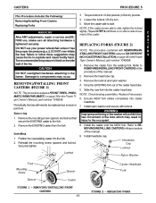
...: If the caster moves side to components may occur. 1. slightly. INCH CASTER INSTALLATION on page 38 in the Power Therecommendedtirepressureislistedontheside Tiger Owner’s Manual, part number 1045938. Removing 1. Remove the locknut and nylon washer. 4. WARNING Improper positioning of the forks which may STALLING FRONT CASTERS replaces SIX OR EIGHT S cause the... procedure replaces FRONT TIRES - Install headtube cap. wall of the caster. PNEUMATIC/SEMI-PNEUMATIC on page 36 in the Power Tiger Owner’s Manual, part number 1045938. E R the tires.
...: If the caster moves side to components may occur. 1. slightly. INCH CASTER INSTALLATION on page 38 in the Power Therecommendedtirepressureislistedontheside Tiger Owner’s Manual, part number 1045938. Removing 1. Remove the locknut and nylon washer. 4. WARNING Improper positioning of the forks which may STALLING FRONT CASTERS replaces SIX OR EIGHT S cause the... procedure replaces FRONT TIRES - Install headtube cap. wall of the caster. PNEUMATIC/SEMI-PNEUMATIC on page 36 in the Power Tiger Owner’s Manual, part number 1045938. E R the tires.
Owners Manual
Page 20
... from the base frame. Before removing the crossmembers, note the mounting hole position of the seat plate in the Power Tiger Owner’s Manual, part number 1045938. 1.
... from the base frame. Before removing the crossmembers, note the mounting hole position of the seat plate in the Power Tiger Owner’s Manual, part number 1045938. 1.

Owners Manual
Page 25
... angle plates are at the angle noted previously, with the mounting holes in the seat rail determined in the Power Tiger Owner’s Manual, part number 1045938. Securely tighten. BACK ANGLE PLATE MOUNTING HOLES FOR CORRESPONDING BACK ANGLES Wheelchair Frame Locknut Washer Coved Washers FIGURE 4 - R MENT on page 49 in STEP...
... angle plates are at the angle noted previously, with the mounting holes in the seat rail determined in the Power Tiger Owner’s Manual, part number 1045938. Securely tighten. BACK ANGLE PLATE MOUNTING HOLES FOR CORRESPONDING BACK ANGLES Wheelchair Frame Locknut Washer Coved Washers FIGURE 4 - R MENT on page 49 in STEP...

Owners Manual
Page 28
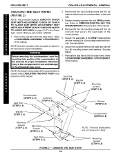
... adjustable pivot point except for Front Riggings A D J U S T M E Front N Crossmember T Rear of Seat Plate S Crossmember of Seat Plate Front of Wheelchair POSITION 1 USE MOUNTING HOLES NUMBER 1 AND 8 POSITION 4 USE MOUNTING HOLES NUMBER 4 AND 11 S Mounting Mounting T Hole 8 Hole 1 Mounting Mounting A Hole 11 Hole 4 B I XX XX XX XX XX XX L I T Y POSITION 2 USE MOUNTING HOLES...
... adjustable pivot point except for Front Riggings A D J U S T M E Front N Crossmember T Rear of Seat Plate S Crossmember of Seat Plate Front of Wheelchair POSITION 1 USE MOUNTING HOLES NUMBER 1 AND 8 POSITION 4 USE MOUNTING HOLES NUMBER 4 AND 11 S Mounting Mounting T Hole 8 Hole 1 Mounting Mounting A Hole 11 Hole 4 B I XX XX XX XX XX XX L I T Y POSITION 2 USE MOUNTING HOLES...
Owners Manual
Page 35
... products to state. LIMITATIONS AND EXCLUSIONS: THE FOREGOING WARRANTY SHALL NOT APPLY TO SERIAL NUMBERED PRODUCTS IF THE SERIAL NUMBER HAS BEEN REMOVED OR DEFACED, PRODUCTS SUBJECTED TO NEGLIGENCE, ACCIDENT, IMPROPER OPERATION, MAINTENANCE OR STORAGE, PRODUCTS MODIFIED WITHOUT INVACARE’S EXPRESS WRITTEN CONSENT INCLUDING, BUT NOT LIMITED TO, MODIFICATION THROUGH THE USE OF...
... products to state. LIMITATIONS AND EXCLUSIONS: THE FOREGOING WARRANTY SHALL NOT APPLY TO SERIAL NUMBERED PRODUCTS IF THE SERIAL NUMBER HAS BEEN REMOVED OR DEFACED, PRODUCTS SUBJECTED TO NEGLIGENCE, ACCIDENT, IMPROPER OPERATION, MAINTENANCE OR STORAGE, PRODUCTS MODIFIED WITHOUT INVACARE’S EXPRESS WRITTEN CONSENT INCLUDING, BUT NOT LIMITED TO, MODIFICATION THROUGH THE USE OF...

