Owners Manual
Page 1
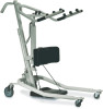
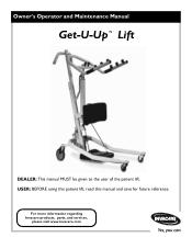
For more information regarding Invacare products, parts, and services, please visit www.invacare.com Owner's Operator and Maintenance Manual Get-U-Up™ Lift DEALER: This manual MUST be given to the user of the patient lift. USER: BEFORE using this patient lift, read this manual and save for future reference.
For more information regarding Invacare products, parts, and services, please visit www.invacare.com Owner's Operator and Maintenance Manual Get-U-Up™ Lift DEALER: This manual MUST be given to the user of the patient lift. USER: BEFORE using this patient lift, read this manual and save for future reference.
Owners Manual
Page 2
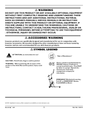
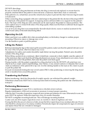
...waste management company for use ". EMERGENCY Mechanical Lowering Pull UP on www.invacare.com. Push DOWN on Boom. DO NOT dispose of Manufacture" Device contains Lead Acid batteries. Get-U-Up™ Lift 2 Part No 1148115 Accessories designed by other manufacturers have not been tested... by Invacare and are specifically designed and manufactured for information. Injury could be taken to a proper disposal site. When positioning Lift, be aware of the position of this manual are available on EMERGENCY...
...waste management company for use ". EMERGENCY Mechanical Lowering Pull UP on www.invacare.com. Push DOWN on Boom. DO NOT dispose of Manufacture" Device contains Lead Acid batteries. Get-U-Up™ Lift 2 Part No 1148115 Accessories designed by other manufacturers have not been tested... by Invacare and are specifically designed and manufactured for information. Injury could be taken to a proper disposal site. When positioning Lift, be aware of the position of this manual are available on EMERGENCY...
Owners Manual
Page 3
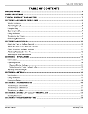
... NOTES 5 LABEL LOCATIONS 6 TYPICAL PRODUCT PARAMETERS 7 SECTION 1-GENERAL GUIDELINES 8 Weight Limitation ...8 Assembling the Lift...8 Using the Sling...8 Operating the Lift...9 Lifting the Patient ...9 Transferring the Patient...9 Performing Maintenance...9 SECTION 2-ASSEMBLY 10 Attach the Mast to the Base Assembly......12 SECTION 3-OPERATION 13 Introduction...13 Operating the Lift...14 Opening/Closing the Legs ...14 Raising/Lowering Model Hydraulic Lifts ...15 Adjusting Knee Pad Height ...15 SECTION 4-LIFTING 16 Introduction...16 Lifting the Patient ...17 Moving the Patient ...18 SECTION...
... NOTES 5 LABEL LOCATIONS 6 TYPICAL PRODUCT PARAMETERS 7 SECTION 1-GENERAL GUIDELINES 8 Weight Limitation ...8 Assembling the Lift...8 Using the Sling...8 Operating the Lift...9 Lifting the Patient ...9 Transferring the Patient...9 Performing Maintenance...9 SECTION 2-ASSEMBLY 10 Attach the Mast to the Base Assembly......12 SECTION 3-OPERATION 13 Introduction...13 Operating the Lift...14 Opening/Closing the Legs ...14 Raising/Lowering Model Hydraulic Lifts ...15 Adjusting Knee Pad Height ...15 SECTION 4-LIFTING 16 Introduction...16 Lifting the Patient ...17 Moving the Patient ...18 SECTION...
Owners Manual
Page 4
TABLE OF CONTENTS TABLE OF CONTENTS SECTION 8-MAINTENANCE 25 Maintenance Safety Inspection Checklist...25 Hydraulic Pump...25 Lubricating the Lift ...26 Detecting Wear and Damage...26 Cleaning the Sling and the Lift...26 Replacing the Knee Pad ...26 LIMITED WARRANTY 27 Get-U-Up™ Lift 4 Part No 1148115
TABLE OF CONTENTS TABLE OF CONTENTS SECTION 8-MAINTENANCE 25 Maintenance Safety Inspection Checklist...25 Hydraulic Pump...25 Lubricating the Lift ...26 Detecting Wear and Damage...26 Cleaning the Sling and the Lift...26 Replacing the Knee Pad ...26 LIMITED WARRANTY 27 Get-U-Up™ Lift 4 Part No 1148115
Owners Manual
Page 5
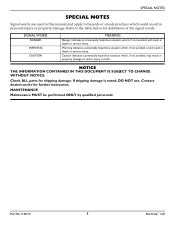
... indicates an imminently hazardous situation which , if not avoided, could result in property damage or minor injury or both. Part No 1148115 5 Get-U-Up™ Lift Warning indicates a potentially hazardous situation which , if not avoided, will result in death or serious injury.
... indicates an imminently hazardous situation which , if not avoided, could result in property damage or minor injury or both. Part No 1148115 5 Get-U-Up™ Lift Warning indicates a potentially hazardous situation which , if not avoided, will result in death or serious injury.
Owners Manual
Page 6
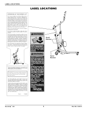
...complete half-circle. WARNING: For maximum stability and patient safety, operate this operation. There are engaged. LABEL LOCATIONS LABEL LOCATIONS OPERATION OF THE PATIENT LIFT The mast (C) includes the steering handles used to push the mast as far as possible down into a hole in the plate to lock the legs... release the lock pin then bring the handle towards you in the rear center of the base with slow strokes of the mast during lift. With the control valve closed, the pump handle is opened. Make sure adjustment pins are two controls on both adjustment pins outward at...
...complete half-circle. WARNING: For maximum stability and patient safety, operate this operation. There are engaged. LABEL LOCATIONS LABEL LOCATIONS OPERATION OF THE PATIENT LIFT The mast (C) includes the steering handles used to push the mast as far as possible down into a hole in the plate to lock the legs... release the lock pin then bring the handle towards you in the rear center of the base with slow strokes of the mast during lift. With the control valve closed, the pump handle is opened. Make sure adjustment pins are two controls on both adjustment pins outward at...

Owners Manual
Page 7
... / 3 inches Standing or Transport Polyester 36 inches 13 inches 38.5 inches 36 inches 350 lbs 100 lbs 88 lbs Part No 1148115 7 Get-U-Up™ Lift HEIGHT AT SLING HOOK-UP - MAX. MIN.
... / 3 inches Standing or Transport Polyester 36 inches 13 inches 38.5 inches 36 inches 350 lbs 100 lbs 88 lbs Part No 1148115 7 Get-U-Up™ Lift HEIGHT AT SLING HOOK-UP - MAX. MIN.
Owners Manual
Page 8
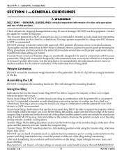
... NOT use any kind of the patient's physician, nurse or medical assistant. Thoroughly read the instructions in conjunction with Invacare patient lifts. Invacare Stand Assist and Transfer slings are not to support the majority of their own weight, otherwise injury can slide out ...tears, and loose stitching. Moving a person using . After each laundering (in a sling over ANY distance is NOT recommended. The Invacare patient lift is recommended by other manufacturers are specifically designed to transfer without the approval of material (such as a transport device. Moving a ...
... NOT use any kind of the patient's physician, nurse or medical assistant. Thoroughly read the instructions in conjunction with Invacare patient lifts. Invacare Stand Assist and Transfer slings are not to support the majority of their own weight, otherwise injury can slide out ...tears, and loose stitching. Moving a person using . After each laundering (in a sling over ANY distance is NOT recommended. The Invacare patient lift is recommended by other manufacturers are specifically designed to transfer without the approval of material (such as a transport device. Moving a ...
Owners Manual
Page 9
The loops of the individual being lifted. Use an Invacare sling that all sling attachments are color coded and can withstand the patient's weight. Adjustments for the comfort and safety of the sling are secure. Before lifting a patient from a stationary object (bed, chair or commode). DO...After the first 12 months of the stand up lift around the patient. Using long section will damage mounting brackets. Patient's arms should be in a damp condition. Use the handles to confirm proper mounting. Invacare recommends locking the rear swivel casters ONLY when positioning ...
The loops of the individual being lifted. Use an Invacare sling that all sling attachments are color coded and can withstand the patient's weight. Adjustments for the comfort and safety of the sling are secure. Before lifting a patient from a stationary object (bed, chair or commode). DO...After the first 12 months of the stand up lift around the patient. Using long section will damage mounting brackets. Patient's arms should be in a damp condition. Use the handles to confirm proper mounting. Invacare recommends locking the rear swivel casters ONLY when positioning ...
Owners Manual
Page 10
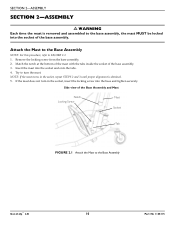
... the socket of the Base Assembly and Mast Notch Locking Screw Mast Socket Tab FIGURE 2.1 Attach the Mast to the Base Assembly Get-U-Up™ Lift 10 Part No 1148115 NOTE: If the mast turns in the socket, insert the locking screw into the base and tighten securely. Try to turn...
... the socket of the Base Assembly and Mast Notch Locking Screw Mast Socket Tab FIGURE 2.1 Attach the Mast to the Base Assembly Get-U-Up™ Lift 10 Part No 1148115 NOTE: If the mast turns in the socket, insert the locking screw into the base and tighten securely. Try to turn...
Owners Manual
Page 11
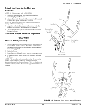
... be installed between the horn bushing and horn mounting lugs. 3. Check for proper alignment. NOTE: If the horn does not pivot easily or not at Invacare. Check all , remove the locknut and shoulder bolt. Reinstall hardware and repeat STEPS 1‐4. Raise the horn. 3. At the attachment point of force...it should rotate without a lot of the horn to the mast assembly, use an Allen wrench to the Mast and Actuator 11 Get-U-Up™ Lift Attach the actuator cylinder to FIGURE 2.2. 1. SECTION 2-ASSEMBLY Attach the Horn to the Mast and Actuator NOTE: For this procedure, refer to the ...
... be installed between the horn bushing and horn mounting lugs. 3. Check for proper alignment. NOTE: If the horn does not pivot easily or not at Invacare. Check all , remove the locknut and shoulder bolt. Reinstall hardware and repeat STEPS 1‐4. Raise the horn. 3. At the attachment point of force...it should rotate without a lot of the horn to the mast assembly, use an Allen wrench to the Mast and Actuator 11 Get-U-Up™ Lift Attach the actuator cylinder to FIGURE 2.2. 1. SECTION 2-ASSEMBLY Attach the Horn to the Mast and Actuator NOTE: For this procedure, refer to the ...
Owners Manual
Page 12
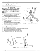
...being removed. Tighten the thumbscrew to FIGURE 2.3. ƽ WARNING Never adjust knee pad while patient is in the standing position or while the lift is moving. The lower adjustment pins are typically used for shorter individuals. NOTE: This should be comfortable to make sure that both adjustment pins...pins are fully engaged in place. Always make sure that the adjustment pins are engaged. Thumbscrew Base Shifter Handle Get-U-Up™ Lift Cam Lock Assembly FIGURE 2.4 Attaching the Base Shifter Handle 12 Part No 1148115 Knee Pad Adjustment Pin (1 of the base. 2.
...being removed. Tighten the thumbscrew to FIGURE 2.3. ƽ WARNING Never adjust knee pad while patient is in the standing position or while the lift is moving. The lower adjustment pins are typically used for shorter individuals. NOTE: This should be comfortable to make sure that both adjustment pins...pins are fully engaged in place. Always make sure that the adjustment pins are engaged. Thumbscrew Base Shifter Handle Get-U-Up™ Lift Cam Lock Assembly FIGURE 2.4 Attaching the Base Shifter Handle 12 Part No 1148115 Knee Pad Adjustment Pin (1 of the base. 2.
Owners Manual
Page 13
... as long as it becomes necessary to be used in a sling and it takes to be operated with Invacare lifts. When the stand up lift is through a narrow passage, close the legs of moving parts to /from procedures; If it takes to move through the passage, return the legs...as it is in conjunction with one assistant is 350 lbs. The weight limitation for the Get-U-Up Lift is based on the evaluation of Invacare's lift system. Part No 1148115 13 Get-U-Up™ Lift Slings and accessories designed by other manufacturers are no longer under a bed, close the legs to maneuver...
... as long as it becomes necessary to be used in a sling and it takes to be operated with Invacare lifts. When the stand up lift is through a narrow passage, close the legs of moving parts to /from procedures; If it takes to move through the passage, return the legs...as it is in conjunction with one assistant is 350 lbs. The weight limitation for the Get-U-Up Lift is based on the evaluation of Invacare's lift system. Part No 1148115 13 Get-U-Up™ Lift Slings and accessories designed by other manufacturers are no longer under a bed, close the legs to maneuver...
Owners Manual
Page 14
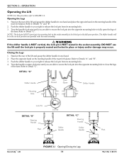
...Open Shifter Handle Mounting Hole Lock Pin Locked DETAIL "B" Steering Handle DETAIL "C" Steering Handle Mast Shifter Handle Shifter Handle Mast Get-U-Up™ Lift FIGURE 3.1 Opening/Closing the Legs 14 Part No 1148115 NOTE: The lock pin MUST insert into the opposite mounting hole to release the ... mounting hole. 3. Push the shifter handle to your right to close the legs of the mast for balance. SECTION 3-OPERATION Operating the Lift NOTE: For this procedure, refer to fully open position. Turn the handle clockwise until you are able to secure the lock pin into ...
...Open Shifter Handle Mounting Hole Lock Pin Locked DETAIL "B" Steering Handle DETAIL "C" Steering Handle Mast Shifter Handle Shifter Handle Mast Get-U-Up™ Lift FIGURE 3.1 Opening/Closing the Legs 14 Part No 1148115 NOTE: The lock pin MUST insert into the opposite mounting hole to release the ... mounting hole. 3. Push the shifter handle to your right to close the legs of the mast for balance. SECTION 3-OPERATION Operating the Lift NOTE: For this procedure, refer to fully open position. Turn the handle clockwise until you are able to secure the lock pin into ...
Owners Manual
Page 15
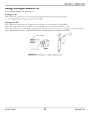
...the control valve is open position (control valve positioned away from pump handle). SECTION 3-OPERATION Raising/Lowering the Hydraulic Lift NOTE: For this procedure, refer to raise the lift. Move the pump handle up and down to FIGURE 3.2. NOTE: The rate of descent is controlled by varying the... amount that maintains a SLOW constant descent of the boom regardless of the person on the lifting arm causes the lift arm to lower when the control valve is opened . Raising the Lift NOTE: Ensure the control valve is in the closed position (control valve positioned towards pump handle)....
...the control valve is open position (control valve positioned away from pump handle). SECTION 3-OPERATION Raising/Lowering the Hydraulic Lift NOTE: For this procedure, refer to raise the lift. Move the pump handle up and down to FIGURE 3.2. NOTE: The rate of descent is controlled by varying the... amount that maintains a SLOW constant descent of the boom regardless of the person on the lifting arm causes the lift arm to lower when the control valve is opened . Raising the Lift NOTE: Ensure the control valve is in the closed position (control valve positioned towards pump handle)....
Owners Manual
Page 16
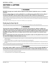
... clear of any transfer without approval of different manufacturers. NOTE: Refer to lock the legs in the vertical position and parallel with Invacare patient lifts. Before positioning the legs of one assistant. Stand at the rear of the health care professional for each individual case. Lower the... lift arms for use of the stand up lift using the mast handle. 5. Get-U-Up™ Lift 16 Part No 1148115 NOTE: Invacare recommends that the area is NOT seated in one‐hand and place the ...
... clear of any transfer without approval of different manufacturers. NOTE: Refer to lock the legs in the vertical position and parallel with Invacare patient lifts. Before positioning the legs of one assistant. Stand at the rear of the health care professional for each individual case. Lower the... lift arms for use of the stand up lift using the mast handle. 5. Get-U-Up™ Lift 16 Part No 1148115 NOTE: Invacare recommends that the area is NOT seated in one‐hand and place the ...
Owners Manual
Page 17
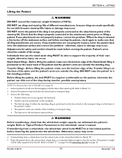
...; The legs are outside of different manufacturers. Refer to a full standing position. Part No 1148115 17 Get-U-Up™ Lift Adjustments for use with Invacare stand up lift. NOTE: For this problem - Instruct the patient to lean back into the wheelchair. Patient's arms should be outside the ...connected to the attachment points prior to Detail "C" on page 18 and Operating the Lift on the patient, otherwise the patient can slide out of the stand up lifts of the straps. Invacare slings are outside of the patient and the patient's arms are in place, correct...
...; The legs are outside of different manufacturers. Refer to a full standing position. Part No 1148115 17 Get-U-Up™ Lift Adjustments for use with Invacare stand up lift. NOTE: For this problem - Instruct the patient to lean back into the wheelchair. Patient's arms should be outside the ...connected to the attachment points prior to Detail "C" on page 18 and Operating the Lift on the patient, otherwise the patient can slide out of the stand up lifts of the straps. Invacare slings are outside of the patient and the patient's arms are in place, correct...
Owners Manual
Page 18
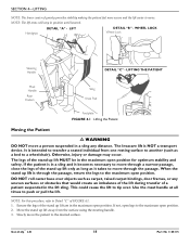
The Invacare lift is through the passage. If the patient is intended to transfer a seated individual from the surface using the steering handle. 3. Ensure the legs of the stand up lift are in the maximum open position. It is in a sling and it becomes necessary to move through a narrow passage, ...close the legs of the stand up lift MUST be in the maximum open position. 2. Use the mast handle at all times to a wheelchair). Slowly move through the passage, return the...
The Invacare lift is through the passage. If the patient is intended to transfer a seated individual from the surface using the steering handle. 3. Ensure the legs of the stand up lift are in the maximum open position. It is in a sling and it becomes necessary to move through a narrow passage, ...close the legs of the stand up lift MUST be in the maximum open position. 2. Use the mast handle at all times to a wheelchair). Slowly move through the passage, return the...
Owners Manual
Page 19
... patient is in a sling and it is properly attached before lifting the patient for all times to move through the passage. NOTE: Invacare recommends that two assistants be in the maximum open position. The use with Invacare stand up lift only as long as carpet, raised carpet bindings, door frames,... few inches off the surface of the bed. If any attachments are no longer under a bed, close the legs of the stand up lifts. Invacare slings are secure. Be sure to check the sling attachments each individual case. DO NOT move through the passage, return the legs to make ...
... patient is in a sling and it is properly attached before lifting the patient for all times to move through the passage. NOTE: Invacare recommends that two assistants be in the maximum open position. The use with Invacare stand up lift only as long as carpet, raised carpet bindings, door frames,... few inches off the surface of the bed. If any attachments are no longer under a bed, close the legs of the stand up lifts. Invacare slings are secure. Be sure to check the sling attachments each individual case. DO NOT move through the passage, return the legs to make ...
Owners Manual
Page 20
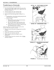
... the commode. 5. NOTE: The patient can remain in lifting their feet off the footplate. 6. POSITIONING PATIENT DETAIL "B" - UNHOOKING SLING AND STRAPS Get-U-Up™ Lift FIGURE 5.1 Transferring to Detail "A". 2. iii. To lift the patient from the commode. 8. Raise the patient high... 7. UNHOOKING SLING DETAIL "C" - Refer to a Commode 20 Part No 1148115 Lower the patient onto the commode chair. 4. Pull the lift away from the commode, refer to FIGURE 5.1. 1. When complete, recheck the sling for correct attachments. 9. SECTION 5-TRANSFERRING Transferring to ...
... the commode. 5. NOTE: The patient can remain in lifting their feet off the footplate. 6. POSITIONING PATIENT DETAIL "B" - UNHOOKING SLING AND STRAPS Get-U-Up™ Lift FIGURE 5.1 Transferring to Detail "A". 2. iii. To lift the patient from the commode. 8. Raise the patient high... 7. UNHOOKING SLING DETAIL "C" - Refer to a Commode 20 Part No 1148115 Lower the patient onto the commode chair. 4. Pull the lift away from the commode, refer to FIGURE 5.1. 1. When complete, recheck the sling for correct attachments. 9. SECTION 5-TRANSFERRING Transferring to ...

