User Guide
Page 14
... 57 Replacing a System Fan ...60 Installing and Removing the Rack Handles 62 Installing the Rack Handles 62 Removing the Rack Handles 63 Chapter 4: Server Utilities 65 Using the BIOS Setup Utility 65 Starting Setup ...65 If You Cannot Access Setup 65 Setup Menus ...65 Upgrading the BIOS ...67 xiv Intel® Server System SR2520SA User...
... 57 Replacing a System Fan ...60 Installing and Removing the Rack Handles 62 Installing the Rack Handles 62 Removing the Rack Handles 63 Chapter 4: Server Utilities 65 Using the BIOS Setup Utility 65 Starting Setup ...65 If You Cannot Access Setup 65 Setup Menus ...65 Upgrading the BIOS ...67 xiv Intel® Server System SR2520SA User...
User Guide
Page 19
... SR2520SAXR/SR2520SAXSR 40 Figure 29. ChassisComponents (SR2520SAX/SR2520SAXS and SR2520SAXR/ SR2520SAXSR)...7 Figure 3. Intel® Server System SR2520SAX/SR2520SAXS and SR2520SAXR/SR2520SAXSR Back Panel Connectors...13 Figure 10. Removing the Front Bezel 25 Figure 16. Installing the Processor Air Duct 30 Figure 21. Intel® Server System SR2520SA 3 Figure 2. Recovery Jumpers 11 Figure 7. Front View with Bezel 24...
... SR2520SAXR/SR2520SAXSR 40 Figure 29. ChassisComponents (SR2520SAX/SR2520SAXS and SR2520SAXR/ SR2520SAXSR)...7 Figure 3. Intel® Server System SR2520SAX/SR2520SAXS and SR2520SAXR/SR2520SAXSR Back Panel Connectors...13 Figure 10. Removing the Front Bezel 25 Figure 16. Installing the Processor Air Duct 30 Figure 21. Intel® Server System SR2520SA 3 Figure 2. Recovery Jumpers 11 Figure 7. Front View with Bezel 24...
User Guide
Page 26
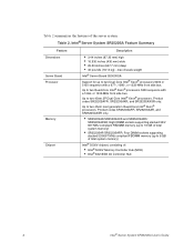
... a 677-, 1066-, or 1333-MHz front side bus. Product codes SR2520SAFR, SR2520SAXR, and SR2520SAXSR only. or 1333-MHz front side bus. Table 2. Intel® Server System SR2520SA Feature Summary Feature Dimensions Server Board Processor Memory Chipset Description • 3.44 inches (87.30 mm) high • 16.930 inches (430 mm) wide • 25.50 inches...
... a 677-, 1066-, or 1333-MHz front side bus. Product codes SR2520SAFR, SR2520SAXR, and SR2520SAXSR only. or 1333-MHz front side bus. Table 2. Intel® Server System SR2520SA Feature Summary Feature Dimensions Server Board Processor Memory Chipset Description • 3.44 inches (87.30 mm) high • 16.930 inches (430 mm) wide • 25.50 inches...

User Guide
Page 31
...* x4 Slot 3 E. System ID LED (SR2520SAX/ SR2520SAXS and SR2520SAXR/SR2520SAXSR only) K. DIMM Sockets (only 4 on SR2520SAF) Q. Processor Fan 2 Header T. SAS RAID 5 Key (SR2520SAX/ SR2520SAXS and SR2520SAXR/SR2520SAXSR only) Z. SATA SGPIO II. SATA 4/SAS 2 Connector C. Processor 1 Socket R. Processor Fan 1 Header U. Processor Power Connector X. System Fan 2 GG. SATA 2/SAS 0 Connector MM. SATA 5/SAS 3 Connector Intel® Server System SR2520SA User's Guide 9
...* x4 Slot 3 E. System ID LED (SR2520SAX/ SR2520SAXS and SR2520SAXR/SR2520SAXSR only) K. DIMM Sockets (only 4 on SR2520SAF) Q. Processor Fan 2 Header T. SAS RAID 5 Key (SR2520SAX/ SR2520SAXS and SR2520SAXR/SR2520SAXSR only) Z. SATA SGPIO II. SATA 4/SAS 2 Connector C. Processor 1 Socket R. Processor Fan 1 Header U. Processor Power Connector X. System Fan 2 GG. SATA 2/SAS 0 Connector MM. SATA 5/SAS 3 Connector Intel® Server System SR2520SA User's Guide 9

User Guide
Page 50
Observe the safety and ESD precautions at the beginning of this book. Remove the server system cover. For instructions on processor installations and removals. See ""Safety Information". 2. Lift the processor air duct from its location over the two processor sockets. 28 Intel® Server System SR2520SA User's Guide The air duct is required for instructions on adding or replacing...
Observe the safety and ESD precautions at the beginning of this book. Remove the server system cover. For instructions on processor installations and removals. See ""Safety Information". 2. Lift the processor air duct from its location over the two processor sockets. 28 Intel® Server System SR2520SA User's Guide The air duct is required for instructions on adding or replacing...

User Guide
Page 51
Removing the Processor Air Duct Intel® Server System SR2520SA User's Guide 29 AF001447 Figure 19.
Removing the Processor Air Duct Intel® Server System SR2520SA User's Guide 29 AF001447 Figure 19.

User Guide
Page 52
... unplug all peripheral devices and the AC power cable(s) into the server. 30 Intel® Server System SR2520SA User's Guide For instructions, see "Installing the System Cover". 6. Plug all peripheral devices and the AC power cable(s). 3. Place the processor air duct over the processor socket(s). Use caution not to pinch or disengage cables that may be near...
... unplug all peripheral devices and the AC power cable(s) into the server. 30 Intel® Server System SR2520SA User's Guide For instructions, see "Installing the System Cover". 6. Plug all peripheral devices and the AC power cable(s). 3. Place the processor air duct over the processor socket(s). Use caution not to pinch or disengage cables that may be near...

User Guide
Page 55
... in "Safety Information". 2. Remove the AC power cord(s) from the server. Replace the system's cover and reconnect the AC power cord(s). Disconnect the AC power cord(s) from the server. 4. Intel® Server System SR2520SA User's Guide 33 Turn off all peripheral devices connected to the processor by the edges, lift it from the socket. 6. Observe the safety...
... in "Safety Information". 2. Remove the AC power cord(s) from the server. Replace the system's cover and reconnect the AC power cord(s). Disconnect the AC power cord(s) from the server. 4. Intel® Server System SR2520SA User's Guide 33 Turn off all peripheral devices connected to the processor by the edges, lift it from the socket. 6. Observe the safety...

User Guide
Page 56
... cutout align correctly. 34 Intel® Server System SR2520SA User's Guide Remove the heat sink, if installed. 7. AF000176 Figure 22. Installing the Processor AF000177 Note: Do not touch the socket pins; Line up the alignment marks on the processor and the socket, and insert the processor into the socket. Locate the processor socket and raise the socket...
... cutout align correctly. 34 Intel® Server System SR2520SA User's Guide Remove the heat sink, if installed. 7. AF000176 Figure 22. Installing the Processor AF000177 Note: Do not touch the socket pins; Line up the alignment marks on the processor and the socket, and insert the processor into the socket. Locate the processor socket and raise the socket...

User Guide
Page 57
... 24. Do no fully tighten one screw before tightening another. 3. 10. Note: Retain the protective socket cover for use when removing a processor that will not be replaced. Gradually and equally tighten each captive screw until each is firmly tightened. Remove the protective socket cover (see Figure...the heat sink so you do not damage the TIM. 1. Set the heat sink over the processor, lining up the four captive screws with the four posts surrounding the processor. 2. Intel® Server System SR2520SA User's Guide 35 Removing the Socket Cover 11. Lower the CPU load plate and lower ...
... 24. Do no fully tighten one screw before tightening another. 3. 10. Note: Retain the protective socket cover for use when removing a processor that will not be replaced. Gradually and equally tighten each captive screw until each is firmly tightened. Remove the protective socket cover (see Figure...the heat sink so you do not damage the TIM. 1. Set the heat sink over the processor, lining up the four captive screws with the four posts surrounding the processor. 2. Intel® Server System SR2520SA User's Guide 35 Removing the Socket Cover 11. Lower the CPU load plate and lower ...

User Guide
Page 58
.... 5. Do not force the heat sink from the server. 4. Replace the system's cover and reconnect the AC power cord(s). Remove the AC power cord(s) from the processor. If it does not pull up easily, twist the heat sink again. Lift the processor lever. 36 Intel® Server System SR2520SA User's Guide Observe the safety and ESD precautions...
.... 5. Do not force the heat sink from the server. 4. Replace the system's cover and reconnect the AC power cord(s). Remove the AC power cord(s) from the processor. If it does not pull up easily, twist the heat sink again. Lift the processor lever. 36 Intel® Server System SR2520SA User's Guide Observe the safety and ESD precautions...

User Guide
Page 59
... front of supported hardware. 9. Raise the CPU load plate. 10. Intel® Server System SR2520SA User's Guide 37 See "Server System References" for an Internet link to your server system, do not use older style drive carriers. Remove the front bezel if it is installed. Remove the processor. 11. Otherwise, install the protective socket cover over the empty...
... front of supported hardware. 9. Raise the CPU load plate. 10. Intel® Server System SR2520SA User's Guide 37 See "Server System References" for an Internet link to your server system, do not use older style drive carriers. Remove the front bezel if it is installed. Remove the processor. 11. Otherwise, install the protective socket cover over the empty...

User Guide
Page 70
... "Removing the Processor Air Duct". 5. For instructions, see "Removing the System Cover". 4. Installing an Add-In Card AF001453 Note: Make sure that all peripheral devices and the AC power cable(s). 3. Remove the server system cover. Remove the screw from the selected add-in card slots have filler panels installed. 48 Intel® Server System SR2520SA User's Guide...
... "Removing the Processor Air Duct". 5. For instructions, see "Removing the System Cover". 4. Installing an Add-In Card AF001453 Note: Make sure that all peripheral devices and the AC power cable(s). 3. Remove the server system cover. Remove the screw from the selected add-in card slots have filler panels installed. 48 Intel® Server System SR2520SA User's Guide...

User Guide
Page 71
Removing a PCI Add-in card slots have filler panels installed. 7. Remove the processor air duct. Intel® Server System SR2520SA User's Guide 49 For instructions, see letter "A"). 6. Remove the screw from the riser card connector (see "Installing the Processor Air Duct". 10. Removing an Add-In Card Note: Make sure that all peripheral devices and the...
Removing a PCI Add-in card slots have filler panels installed. 7. Remove the processor air duct. Intel® Server System SR2520SA User's Guide 49 For instructions, see letter "A"). 6. Remove the screw from the riser card connector (see "Installing the Processor Air Duct". 10. Removing an Add-In Card Note: Make sure that all peripheral devices and the...

User Guide
Page 72
... the beginning of this book. Attach the server board with eight screws (see "Removing the Processor Air Duct". 5. Power down the server and unplug all peripheral devices and the AC power cable(s). 3. B A AF001469 Figure 39. See "Safety Information". 2. For instructions, see letter "B"). Installing the Server Board 50 Intel® Server System SR2520SA User's Guide Installing and Removing...
... the beginning of this book. Attach the server board with eight screws (see "Removing the Processor Air Duct". 5. Power down the server and unplug all peripheral devices and the AC power cable(s). 3. B A AF001469 Figure 39. See "Safety Information". 2. For instructions, see letter "B"). Installing the Server Board 50 Intel® Server System SR2520SA User's Guide Installing and Removing...

User Guide
Page 73
... processor air duct. Removing the Server Board 1. Power down the server and unplug all peripheral devices and the AC power cable(s) into the server. Remove the server system cover. 7. For instructions, see letter "B"). See "Safety Information". 2. Plug all peripheral devices and the AC power cable(s). 3. For instructions, see "Removing the Processor Air Duct". 5. Removing the Server Board Intel® Server System...
... processor air duct. Removing the Server Board 1. Power down the server and unplug all peripheral devices and the AC power cable(s) into the server. Remove the server system cover. 7. For instructions, see letter "B"). See "Safety Information". 2. Plug all peripheral devices and the AC power cable(s). 3. For instructions, see "Removing the Processor Air Duct". 5. Removing the Server Board Intel® Server System...
User Guide
Page 74
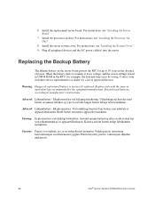
Install the server system cover. Discard used batteries according to weaken, it loses voltage, and the server settings stored in CMOS RAM in the absence of explosion if battery is incorrectly replaced. Levér det brugte batteri tilbage til ... af samme fabrikat og type. Hävitä käytetty paristo valmistajan ohjeiden mukaisesti. 52 Intel® Server System SR2520SA User's Guide 6. For instructions, see "Installing the System Cover". 9. For instructions, see "Installing the Processor Air Duct". 8. Plug all peripheral devices and the AC power cable(s) into the...
Install the server system cover. Discard used batteries according to weaken, it loses voltage, and the server settings stored in CMOS RAM in the absence of explosion if battery is incorrectly replaced. Levér det brugte batteri tilbage til ... af samme fabrikat og type. Hävitä käytetty paristo valmistajan ohjeiden mukaisesti. 52 Intel® Server System SR2520SA User's Guide 6. For instructions, see "Installing the System Cover". 9. For instructions, see "Installing the Processor Air Duct". 8. Plug all peripheral devices and the AC power cable(s) into the...
User Guide
Page 98
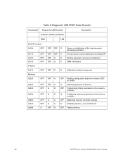
... OFF OFF 0x25h OFF 0x26h 0x27h 0x28h OFF OFF G OFF OFF R OFF OFF A OFF G R OFF G A Power-on initialization of the host processor (bootstrap processor) Host processor cache initialization (including AP) Starting application processor initialization SMM initialization OFF R G Initializing a chipset component OFF A OFF A G R G R G A G A OFF R OFF G OFF G OFF G OFF Reading ...Configuring memory parameters in the memory controller Optimizing memory controller settings Initializing memory, such as ECC init Testing memory 76 Intel® Server System SR2520SA User's Guide
... OFF OFF 0x25h OFF 0x26h 0x27h 0x28h OFF OFF G OFF OFF R OFF OFF A OFF G R OFF G A Power-on initialization of the host processor (bootstrap processor) Host processor cache initialization (including AP) Starting application processor initialization SMM initialization OFF R G Initializing a chipset component OFF A OFF A G R G R G A G A OFF R OFF G OFF G OFF G OFF Reading ...Configuring memory parameters in the memory controller Optimizing memory controller settings Initializing memory, such as ECC init Testing memory 76 Intel® Server System SR2520SA User's Guide
User Guide
Page 120
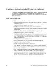
... Are the processors fully seated in their sockets on the server board? • Are all standoffs in the proper location and not touching any components, causing a potential short? • Are all add-in PCI boards fully seated in their slots on the server board? •...Is the operating system properly loaded? Problems following Initial System Installation Problems that there are no conflicts-for 200-240V ? • Are all integrated components from the tested components lists? To check these settings, refer to the tested component lists. 98 Intel® Server System SR2520SA User's Guide...
... Are the processors fully seated in their sockets on the server board? • Are all standoffs in the proper location and not touching any components, causing a potential short? • Are all add-in PCI boards fully seated in their slots on the server board? •...Is the operating system properly loaded? Problems following Initial System Installation Problems that there are no conflicts-for 200-240V ? • Are all integrated components from the tested components lists? To check these settings, refer to the tested component lists. 98 Intel® Server System SR2520SA User's Guide...

User Guide
Page 122
...does not light. • There are problems with the system requirements. • Make sure the processor(s) have been populated according to the system requirements. • Remove the processor(s) and re-seat them . • Make sure the processor(s) comply with application software. • The bootable CD-... have a power switch on ? • Remove all add-in one , is functioning. 100 Intel® Server System SR2520SA User's Guide Test it turned on the back of the server board and cause a short. If your service representative or authorized dealer for help. If successful, add...
...does not light. • There are problems with the system requirements. • Make sure the processor(s) have been populated according to the system requirements. • Remove the processor(s) and re-seat them . • Make sure the processor(s) comply with application software. • The bootable CD-... have a power switch on ? • Remove all add-in one , is functioning. 100 Intel® Server System SR2520SA User's Guide Test it turned on the back of the server board and cause a short. If your service representative or authorized dealer for help. If successful, add...