User Guide
Page 11
... Preface ...vii About this Manual ...vii Manual Organization ...vii Product Contents ...viii Intel® Server System SR2500ALLX/SR2500ALLXR Contents viii Intel® Server System SR2500ALBRP/SR2500ALBRPR Contents ix Chapter 1: Server System References 1 Chapter 2: Server System Features 3 Chassis Component Identification 6 Internal Components ...6 Configuration Jumpers ...9 RAID Support ...13 Standard Control Panel 18 Intel® Local Control Panel 19 Bezels ...20 Peripheral Devices ...22 Hard Disk...
... Preface ...vii About this Manual ...vii Manual Organization ...vii Product Contents ...viii Intel® Server System SR2500ALLX/SR2500ALLXR Contents viii Intel® Server System SR2500ALBRP/SR2500ALBRPR Contents ix Chapter 1: Server System References 1 Chapter 2: Server System Features 3 Chassis Component Identification 6 Internal Components ...6 Configuration Jumpers ...9 RAID Support ...13 Standard Control Panel 18 Intel® Local Control Panel 19 Bezels ...20 Peripheral Devices ...22 Hard Disk...

User Guide
Page 13
...RAID Mini DIMM 77 Installing the RAID Activation Key and the RAID Mini DIMM 77 Removing the RAID Activation Key and the RAID Mini DIMM 78 Installing and Removing the RAID Battery Backup Unit (BBU 79 Installing the RAID Battery Backup Unit 79 Removing the RAID Battery Backup Unit 80 Installing and Removing the Server Board 81 Installing the Server... Fan Connections ...108 750W Single Power Supply Input Voltages 109 750W Single Power Supply Output Voltages 109 System Environmental Specifications 110 Appendix B: Troubleshooting 111 Intel® Server System SR2500AL User's Guide xiii
...RAID Mini DIMM 77 Installing the RAID Activation Key and the RAID Mini DIMM 77 Removing the RAID Activation Key and the RAID Mini DIMM 78 Installing and Removing the RAID Battery Backup Unit (BBU 79 Installing the RAID Battery Backup Unit 79 Removing the RAID Battery Backup Unit 80 Installing and Removing the Server Board 81 Installing the Server... Fan Connections ...108 750W Single Power Supply Input Voltages 109 750W Single Power Supply Output Voltages 109 System Environmental Specifications 110 Appendix B: Troubleshooting 111 Intel® Server System SR2500AL User's Guide xiii

User Guide
Page 18
... Fan Module 97 xviii Intel® Server System SR2500AL User's Guide Removing the Mid-plane from the Server System 75 Figure 66. Removing the Backplane from the Server System 72 Figure 63. Installing the RAID Battery Backup Unit 79 Figure 70. Removing Power Supply Module from the Server System 71 Figure 62. Installing a Fan into the Server System 73 Figure 64. Removing...
... Fan Module 97 xviii Intel® Server System SR2500AL User's Guide Removing the Mid-plane from the Server System 75 Figure 66. Removing the Backplane from the Server System 72 Figure 63. Installing the RAID Battery Backup Unit 79 Figure 70. Removing Power Supply Module from the Server System 71 Figure 62. Installing a Fan into the Server System 73 Figure 64. Removing...
User Guide
Page 26
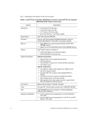
...Intel® Server System SR2500ALLX and/or the Intel® Server System SR2500ALBRP Feature Summary Feature Dimensions Server Board Processor Memory Chipset Peripheral Interfaces I /O Controller Hub External connections: • Stacked PS/2* ports for keyboard and mouse • RJ45 Serial B port • Two RJ45 NIC connectors for 10/100/1000 Mb... connections • Two USB 2.0 ports Internal connections: • One USB port header, which supports two USB 2.0 ports • One DH10 Serial A header • Six Serial ATA 150 connectors with integrated RAID 0/1 support •...
...Intel® Server System SR2500ALLX and/or the Intel® Server System SR2500ALBRP Feature Summary Feature Dimensions Server Board Processor Memory Chipset Peripheral Interfaces I /O Controller Hub External connections: • Stacked PS/2* ports for keyboard and mouse • RJ45 Serial B port • Two RJ45 NIC connectors for 10/100/1000 Mb... connections • Two USB 2.0 ports Internal connections: • One USB port header, which supports two USB 2.0 ports • One DH10 Serial A header • Six Serial ATA 150 connectors with integrated RAID 0/1 support •...
User Guide
Page 35
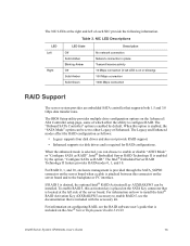
... supports both 1.5 and 3.0 Gbps data transfer rates. Intel® Embedded Server RAID Technology II is enabled by default. Table 3. The Intel® Embedded Server RAID Technology II feature provides RAID modes 0, 1, and 10. If RAID 5 is required for RAID configurations. The "Onboard SATA Controller" option is included with the accessory kit. Intel® Server System SR2500AL User's Guide 13 For information on...
... supports both 1.5 and 3.0 Gbps data transfer rates. Intel® Embedded Server RAID Technology II is enabled by default. Table 3. The Intel® Embedded Server RAID Technology II feature provides RAID modes 0, 1, and 10. If RAID 5 is required for RAID configurations. The "Onboard SATA Controller" option is included with the accessory kit. Intel® Server System SR2500AL User's Guide 13 For information on...

User Guide
Page 36
... SATA (data cables required), and an active SAS/SATA RAID (no data cables required). Fan 4 Power G. Fan 3 Power H. Backplane Connectors Figure 8. Fan 6 Power C. Two midplanes are not used in the Intel® Server System SR2500ALLX and/or the Intel® Server System SR2500ALBRP. 14 Intel® Server System SR2500AL User's Guide Passive Mid-Plane Components Note: SATA connectors 6 and 7 are...
... SATA (data cables required), and an active SAS/SATA RAID (no data cables required). Fan 4 Power G. Fan 3 Power H. Backplane Connectors Figure 8. Fan 6 Power C. Two midplanes are not used in the Intel® Server System SR2500ALLX and/or the Intel® Server System SR2500ALBRP. 14 Intel® Server System SR2500AL User's Guide Passive Mid-Plane Components Note: SATA connectors 6 and 7 are...

User Guide
Page 37
Backplane Connectors Figure 9. Fan 6 Power D. Fan 3 Power H. Fan 5 Power E. Fan 2 Power I J AF000046 A. Fan 4 Power G. Active SAS/SATA Mid-Plane Components Intel® Server System SR2500AL User's Guide 15 RAID Battery Connector B. Bridge Board Connector F. B A C D K E F G H I . Fan 1 Power J. Mid-plane Power Connector C.
Backplane Connectors Figure 9. Fan 6 Power D. Fan 3 Power H. Fan 5 Power E. Fan 2 Power I J AF000046 A. Fan 4 Power G. Active SAS/SATA Mid-Plane Components Intel® Server System SR2500AL User's Guide 15 RAID Battery Connector B. Bridge Board Connector F. B A C D K E F G H I . Fan 1 Power J. Mid-plane Power Connector C.

User Guide
Page 99
... key by releasing the retention mechanism (see "Removing the Large Air Baffle". 5. Installing the RAID Activation Key and the RAID Mini DIMM Intel® Server System SR2500AL User's Guide 77 See "Safety Information". 2. For instructions, see "Removing the System Cover". 4. Plug all peripheral devices and the AC power cable(s). 3. Observe the safety and ESD precautions at...
... key by releasing the retention mechanism (see "Removing the Large Air Baffle". 5. Installing the RAID Activation Key and the RAID Mini DIMM Intel® Server System SR2500AL User's Guide 77 See "Safety Information". 2. For instructions, see "Removing the System Cover". 4. Plug all peripheral devices and the AC power cable(s). 3. Observe the safety and ESD precautions at...

User Guide
Page 100
... beginning of the socket (see "Removing the Large Air Baffle". 5. Plug all peripheral devices and the AC power cable(s) into the server. 78 Intel® Server System SR2500AL User's Guide Remove the RAID activation key by releasing the retention mechanism (see letter "B" in the figure below ) and pulling the DIMM out of this book. For...
... beginning of the socket (see "Removing the Large Air Baffle". 5. Plug all peripheral devices and the AC power cable(s) into the server. 78 Intel® Server System SR2500AL User's Guide Remove the RAID activation key by releasing the retention mechanism (see letter "B" in the figure below ) and pulling the DIMM out of this book. For...

User Guide
Page 101
.... A B AF000149 Figure 69. Insert the RAID battery backup unit into the server system and slide back until it locks into place as shown (see "Installing the Large Air Baffle". 8. Intel® Server System SR2500AL User's Guide 79 Install the large air baffle. Remove the server system cover. For instructions, see letter "A"). 6. Install the server system cover. Observe the safety and...
.... A B AF000149 Figure 69. Insert the RAID battery backup unit into the server system and slide back until it locks into place as shown (see "Installing the Large Air Baffle". 8. Intel® Server System SR2500AL User's Guide 79 Install the large air baffle. Remove the server system cover. For instructions, see letter "A"). 6. Install the server system cover. Observe the safety and...

User Guide
Page 102
... RAID battery backup unit forward and lift from the rear of this book. For instructions, see "Removing the Large Air Baffle". 5. B A AF000150 Figure 70. See "Safety Information". 2. Remove the server system cover. For instructions, see "Installing the Large Air Baffle". 8. Plug all peripheral devices and the AC power cable(s) into the server. 80 Intel® Server System...
... RAID battery backup unit forward and lift from the rear of this book. For instructions, see "Removing the Large Air Baffle". 5. B A AF000150 Figure 70. See "Safety Information". 2. Remove the server system cover. For instructions, see "Installing the Large Air Baffle". 8. Plug all peripheral devices and the AC power cable(s) into the server. 80 Intel® Server System...

User Guide
Page 129
... cables are pinched and that the airflow from your server system, make sure no cables or wires are routed correctly before reinstalling the server system cover. B A C D E F A Power to Server Board (Aux.) B Power to Server Board (Main) C Power to Server Board (CPU) D Power to Midplane Board E Power to Backplane Board F RAID Battery to determine the correct cable routing. Use...
... cables are pinched and that the airflow from your server system, make sure no cables or wires are routed correctly before reinstalling the server system cover. B A C D E F A Power to Server Board (Aux.) B Power to Server Board (Main) C Power to Server Board (CPU) D Power to Midplane Board E Power to Backplane Board F RAID Battery to determine the correct cable routing. Use...

User Guide
Page 141
...unique on setting the SCSI ID for a link to software to install a surge suppressor between the power outlet and the system power cord. Intel® Server System SR2500AL User's Guide 119 See your drive documentation for details on the SCSI bus. Devices are not Recognized Check the ...Microsoft* Windows* Operating System) The Microsoft* Windows* operating systems do not include all of the above symptoms that might indicate voltage spikes on the power line, you have not exceeded the power budget for details on your drives. • If using a RAID configuration with SCSI ...
...unique on setting the SCSI ID for a link to software to install a surge suppressor between the power outlet and the system power cord. Intel® Server System SR2500AL User's Guide 119 See your drive documentation for details on the SCSI bus. Devices are not Recognized Check the ...Microsoft* Windows* Operating System) The Microsoft* Windows* operating systems do not include all of the above symptoms that might indicate voltage spikes on the power line, you have not exceeded the power budget for details on your drives. • If using a RAID configuration with SCSI ...
