User Guide
Page 7
... for a link to add and replace components on using the Intel® Server System SR2500ALLX and/or the Intel® Server System SR2500ALBRP. This includes how to navigate through the BIOS Setup screens, how to perform a BIOS update, and how to help " information, and the warranty. See "Server System References" for purchasing and using the utilities that give additional details...
... for a link to add and replace components on using the Intel® Server System SR2500ALLX and/or the Intel® Server System SR2500ALBRP. This includes how to navigate through the BIOS Setup screens, how to perform a BIOS update, and how to help " information, and the warranty. See "Server System References" for purchasing and using the utilities that give additional details...

User Guide
Page 13
...Module 93 Replacing a Redundant System Fan 95 Replacing a Fixed Fan ...97 Installing and Removing the Rack Handles 98 Installing the Rack Handles 98 Removing the Rack Handles 99 Chapter 4: Server Utilities 101 Using the BIOS Setup Utility 101 Starting Setup...BIOS 104 Clearing the Password ...104 Clearing the CMOS ...105 Appendix A: Technical Reference 107 Cable Routing ...107 Fan Connections ...108 750W Single Power Supply Input Voltages 109 750W Single Power Supply Output Voltages 109 System Environmental Specifications 110 Appendix B: Troubleshooting 111 Intel® Server System...
...Module 93 Replacing a Redundant System Fan 95 Replacing a Fixed Fan ...97 Installing and Removing the Rack Handles 98 Installing the Rack Handles 98 Removing the Rack Handles 99 Chapter 4: Server Utilities 101 Using the BIOS Setup Utility 101 Starting Setup...BIOS 104 Clearing the Password ...104 Clearing the CMOS ...105 Appendix A: Technical Reference 107 Cable Routing ...107 Fan Connections ...108 750W Single Power Supply Input Voltages 109 750W Single Power Supply Output Voltages 109 System Environmental Specifications 110 Appendix B: Troubleshooting 111 Intel® Server System...

User Guide
Page 14
... Correctly Earlier 118 Devices are not Recognized under Device Manager (Microsoft* Windows* Operating System) ...119 Hard Drive(s) are not Recognized 119 Bootable CD-ROM Disk Is Not Detected 119 LED Information ...120 BIOS POST Beep Codes 120 Appendix C: Intel® Server Issue Report Form 123 Appendix D: LED Decoder 127 Appendix E: Getting Help 133 World... Europe (CE Declaration of Conformity 142 VCCI (Japan) ...142 BSMI (Taiwan) ...142 Korean Compliance (RRL 143 CNCA (CCC-China 143 Product Ecology Compliance 143 xiv Intel® Server System SR2500AL User's Guide
... Correctly Earlier 118 Devices are not Recognized under Device Manager (Microsoft* Windows* Operating System) ...119 Hard Drive(s) are not Recognized 119 Bootable CD-ROM Disk Is Not Detected 119 LED Information ...120 BIOS POST Beep Codes 120 Appendix C: Intel® Server Issue Report Form 123 Appendix D: LED Decoder 127 Appendix E: Getting Help 133 World... Europe (CE Declaration of Conformity 142 VCCI (Japan) ...142 BSMI (Taiwan) ...142 Korean Compliance (RRL 143 CNCA (CCC-China 143 Product Ecology Compliance 143 xiv Intel® Server System SR2500AL User's Guide

User Guide
Page 17
BIOS Select Jumper 9 Figure 5. Back Panel Connectors 12 Figure 8. Hot-Swap SAS/SATA Backplane Components (Rear View 17 Figure 12. Server System Back 21 Figure 15. Installing the Server System Cover 32 Figure 22. Removing the Socket Cover 39 Figure 29. Removing the Large Air Baffle 43 Figure 33... Figure 23. Installing the Heat Sink (2U Passive Heat Sink Shown 39 Figure 30. Installing Hard Drive into the Server System 46 Figure 38. Intel® Local Control Panel 20 Figure 14. Front Bezel Supporting the Standard Control Panel 28 Figure 17. Front Bezel Supporting ...
BIOS Select Jumper 9 Figure 5. Back Panel Connectors 12 Figure 8. Hot-Swap SAS/SATA Backplane Components (Rear View 17 Figure 12. Server System Back 21 Figure 15. Installing the Server System Cover 32 Figure 22. Removing the Socket Cover 39 Figure 29. Removing the Large Air Baffle 43 Figure 33... Figure 23. Installing the Heat Sink (2U Passive Heat Sink Shown 39 Figure 30. Installing Hard Drive into the Server System 46 Figure 38. Intel® Local Control Panel 20 Figure 14. Front Bezel Supporting the Standard Control Panel 28 Figure 17. Front Bezel Supporting ...
User Guide
Page 23
... server system, including sub-system overviews and mechanical drawings For basic BIOS settings and chipset information For in-depth BIOS information For in-depth firmware information on the Baseboard Management Controller (BMC) For in -depth technical information about the accessories that can be used with the Intel® Server System SR2500AL: • SR2500ALLX • SR2500ALBRP • SR2500ALLXR • SR2500ALBRPR...
... server system, including sub-system overviews and mechanical drawings For basic BIOS settings and chipset information For in-depth BIOS information For in-depth firmware information on the Baseboard Management Controller (BMC) For in -depth technical information about the accessories that can be used with the Intel® Server System SR2500AL: • SR2500ALLX • SR2500ALBRP • SR2500ALLXR • SR2500ALBRPR...

User Guide
Page 31
BIOS Select Jumper Intel® Server System SR2500AL User's Guide 9 These pins should be selected on 2-3 for normal operation. Figure 4. Configuration Jumpers BIOS Select J3H1 3 3 1-2: Force Lower Bank 2-3: Normal Operation (Default) Jumper Name BIOS Select TP02087 Jumper Purpose If pins 1-2 are jumpered, the BIOS in the lower bank will be jumpered on the next reset.
BIOS Select Jumper Intel® Server System SR2500AL User's Guide 9 These pins should be selected on 2-3 for normal operation. Figure 4. Configuration Jumpers BIOS Select J3H1 3 3 1-2: Force Lower Bank 2-3: Normal Operation (Default) Jumper Name BIOS Select TP02087 Jumper Purpose If pins 1-2 are jumpered, the BIOS in the lower bank will be jumpered on the next reset.
User Guide
Page 35
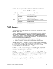
...of each NIC provide the following information. The BIOS Setup utility provides multiple drive configuration options on the server board when a cable is selected, you can be set to the backplane or I2C interface. The Intel® Embedded Server RAID Technology II feature provides RAID modes 0, ...documentation that is located at the right and left LED is on the Intel® Server Deployment Toolkit 2.0 CD. The Legacy and Enhanced modes affect the RAID configuration as RAID". Intel® Server System SR2500AL User's Guide 13 NIC LED Descriptions LED Left Right LED State ...
...of each NIC provide the following information. The BIOS Setup utility provides multiple drive configuration options on the server board when a cable is selected, you can be set to the backplane or I2C interface. The Intel® Embedded Server RAID Technology II feature provides RAID modes 0, ...documentation that is located at the right and left LED is on the Intel® Server Deployment Toolkit 2.0 CD. The Legacy and Enhanced modes affect the RAID configuration as RAID". Intel® Server System SR2500AL User's Guide 13 NIC LED Descriptions LED Left Right LED State ...

User Guide
Page 123
... boot. If a value cannot be changed for CMOS and attempt to the Intel® 5000 Series Chipsets Server Board Family Datasheet where you will see "Clearing the CMOS". See "Server System References" for those features that contains user-selectable parameters. Setup Menus Each BIOS Setup menu page contains a number of features. These parameters can enter...
... boot. If a value cannot be changed for CMOS and attempt to the Intel® 5000 Series Chipsets Server Board Family Datasheet where you will see "Clearing the CMOS". See "Server System References" for those features that contains user-selectable parameters. Setup Menus Each BIOS Setup menu page contains a number of features. These parameters can enter...

User Guide
Page 124
... field pick list. When the key is pressed while editing any submenu, the parent menu is re-entered. When the key is pressed in the BIOS Setup menus. The up - On 106-key Japanese keyboards, the plus key has a different scan code than the plus key or the function key... is pressed, the user is displayed. This key will undo the pick list, and allow another selection in any existing field values. 102 Intel® Server System SR2500AL User's Guide Left and right arrows The left and right arrow keys are set to where they were before was pressed without displaying the...
... field pick list. When the key is pressed while editing any submenu, the parent menu is re-entered. When the key is pressed in the BIOS Setup menus. The up - On 106-key Japanese keyboards, the plus key has a different scan code than the plus key or the function key... is pressed, the user is displayed. This key will undo the pick list, and allow another selection in any existing field values. 102 Intel® Server System SR2500AL User's Guide Left and right arrows The left and right arrow keys are set to where they were before was pressed without displaying the...

User Guide
Page 125
... were before was pressed without affecting any existing values. Upgrading the BIOS The upgrade utility allows you want to obtain the upgrade utility. Recording the Current BIOS Settings 1. Note: Do not skip step 2. Intel® Server System SR2500AL User's Guide 103 Setup Menu Key Use Description Save and... all changes are saved and Setup is returned to service. See "Server System References" for the Upgrade The steps below explain how to prepare to upgrade the BIOS, including how to record the current BIOS settings and how to run SETUP 2. Key to necessary software and ...
... were before was pressed without affecting any existing values. Upgrading the BIOS The upgrade utility allows you want to obtain the upgrade utility. Recording the Current BIOS Settings 1. Note: Do not skip step 2. Intel® Server System SR2500AL User's Guide 103 Setup Menu Key Use Description Save and... all changes are saved and Setup is returned to service. See "Server System References" for the Upgrade The steps below explain how to prepare to upgrade the BIOS, including how to record the current BIOS settings and how to run SETUP 2. Key to necessary software and ...

User Guide
Page 126
... a CMOS Checksum error or other information to the Password Clear Erase position, covering pins 2 and 3. 104 Intel® Server System SR2500AL User's Guide CMOS checksum errors require that are provided in the readme file that came with the BIOS image file before a new password(s) can be restored to a temporary folder on your settings, and...
... a CMOS Checksum error or other information to the Password Clear Erase position, covering pins 2 and 3. 104 Intel® Server System SR2500AL User's Guide CMOS checksum errors require that are provided in the readme file that came with the BIOS image file before a new password(s) can be restored to a temporary folder on your settings, and...

User Guide
Page 127
...Reconnect the AC power and power up the server. 8. Open the server. 3. The password is now cleared and can be used to reset the configuration RAM. 1. Power down the system and disconnect the AC power. 2. Close the server chassis. 7. Return the Password Clear jumper ...2 to the Password Clear Protect position, covering pins 1 and 2. 6. Intel® Server System SR2500AL User's Guide 105 Clear Password Jumper TP02080 4. Move the jumper from the normal operation position, CMOS Clear by going into BIOS setup. BMC Force Update Mode 2 3 J1D2 Password Reset Disable 2 Enable...
...Reconnect the AC power and power up the server. 8. Open the server. 3. The password is now cleared and can be used to reset the configuration RAM. 1. Power down the system and disconnect the AC power. 2. Close the server chassis. 7. Return the Password Clear jumper ...2 to the Password Clear Protect position, covering pins 1 and 2. 6. Intel® Server System SR2500AL User's Guide 105 Clear Password Jumper TP02080 4. Move the jumper from the normal operation position, CMOS Clear by going into BIOS setup. BMC Force Update Mode 2 3 J1D2 Password Reset Disable 2 Enable...

User Guide
Page 128
Wait five seconds. 5. Reconnect the AC power and power up the system. 8. Return the CMOS Clear jumper to the CMOS Clear by going into the BIOS setup. 106 Intel® Server System SR2500AL User's Guide Close the server chassis. 7. Clear CMOS Jumper TP02080 4. BMC Force Update Mode 2 3 J1D2 Password Reset Disable 2 Enable 3 J1D1 2 Clear 3 CMOS J1D3 Figure 92. The CMOS is now cleared and can be reset by BMC location, covering pins 1 and 2. 6.
Wait five seconds. 5. Reconnect the AC power and power up the system. 8. Return the CMOS Clear jumper to the CMOS Clear by going into the BIOS setup. 106 Intel® Server System SR2500AL User's Guide Close the server chassis. 7. Clear CMOS Jumper TP02080 4. BMC Force Update Mode 2 3 J1D2 Password Reset Disable 2 Enable 3 J1D1 2 Clear 3 CMOS J1D3 Figure 92. The CMOS is now cleared and can be reset by BMC location, covering pins 1 and 2. 6.

User Guide
Page 133
...the software updates. Table 7. Resetting the System To do this software. See "Server System References" for BIOS, the Baseboard Management Controller (BMC), and the hotswap controller (HSC). Resetting the System Before going through in your own, see...Server System References" for one of the methods below. This clears system memory, restarts POST, reloads the operating system, and halts power to all peripherals Reset the BMC and get it back to a stable state Press Reset button Power off and then on your system, such as video drivers, network drivers, and SATA drivers. Intel...
...the software updates. Table 7. Resetting the System To do this software. See "Server System References" for BIOS, the Baseboard Management Controller (BMC), and the hotswap controller (HSC). Resetting the System Before going through in your own, see...Server System References" for one of the methods below. This clears system memory, restarts POST, reloads the operating system, and halts power to all peripherals Reset the BMC and get it back to a stable state Press Reset button Power off and then on your system, such as video drivers, network drivers, and SATA drivers. Intel...

User Guide
Page 135
... does not appear, see the documentation supplied with your video display monitor and keyboard are illuminated, see "Power Light Does Not Light". Intel® Server System SR2500AL User's Guide 113 Check for these specific problems: • Power light does not light. • No characters appear on screen. &#... appear distorted or incorrect. Disconnect each device is configured to allow the CD-ROM to the operating system. If the power LED does not light, see "Make sure the BIOS is checked, its brightness and contrast controls to at least two thirds of each mass storage device...
... does not appear, see the documentation supplied with your video display monitor and keyboard are illuminated, see "Power Light Does Not Light". Intel® Server System SR2500AL User's Guide 113 Check for these specific problems: • Power light does not light. • No characters appear on screen. &#... appear distorted or incorrect. Disconnect each device is configured to allow the CD-ROM to the operating system. If the power LED does not light, see "Make sure the BIOS is checked, its brightness and contrast controls to at least two thirds of each mass storage device...

User Guide
Page 137
...emits a beep code, write down the beep code you do not receive a beep code and characters do the following : Intel® Server System SR2500AL User's Guide 115 See the manufacturer's documentation. • Are the video monitor's signal and power cables properly installed?... • Does this video monitor work correctly if plugged into a different system? • Is the onboard video controller enabled in the BIOS? • Remove...
...emits a beep code, write down the beep code you do not receive a beep code and characters do the following : Intel® Server System SR2500AL User's Guide 115 See the manufacturer's documentation. • Are the video monitor's signal and power cables properly installed?... • Does this video monitor work correctly if plugged into a different system? • Is the onboard video controller enabled in the BIOS? • Remove...

User Guide
Page 139
...was installed. • Make sure the cable is connected to the current version. • Make sure the other PCI drivers. Intel® Server System SR2500AL User's Guide 117 See the documentation that interrupts are not shared with other adapter supports shared interrupts. • Make sure...; Run diagnostics. For these drivers, it may be necessary to the NIC connectors. See "Server System References" for a link to the port from the onboard network controller. • Make sure your BIOS is securely attached. • Make sure you will need a crossover cable. • Check...
...was installed. • Make sure the cable is connected to the current version. • Make sure the other PCI drivers. Intel® Server System SR2500AL User's Guide 117 See the documentation that interrupts are not shared with other adapter supports shared interrupts. • Make sure...; Run diagnostics. For these drivers, it may be necessary to the NIC connectors. See "Server System References" for a link to the port from the onboard network controller. • Make sure your BIOS is securely attached. • Make sure you will need a crossover cable. • Check...

User Guide
Page 141
... that the master/slave settings are not Recognized Check the following : • Make sure the BIOS is installed correctly. Hard Drive(s) are set correctly. See "Server System References" for the Intel® chipsets, onboard NICs, and other components. Intel® Server System SR2500AL User's Guide 119 If you are experiencing any of the drivers for a link to...
... that the master/slave settings are not Recognized Check the following : • Make sure the BIOS is installed correctly. Hard Drive(s) are set correctly. See "Server System References" for the Intel® chipsets, onboard NICs, and other components. Intel® Server System SR2500AL User's Guide 119 If you are experiencing any of the drivers for a link to...
User Guide
Page 142
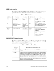
... are not generated after the add-in cards are supported by BIOS beep codes. Table 9. Replace or reseat the system video add-in troubleshooting your system manufacturer. If on and off. Table 8. Prior to system video initialization, the BIOS uses these LEDs with known good modules. If the error still... = Power is on or in sleep stats S0 Press ID LED button or use is bing used, the server board may be faulty. 120 Intel® Server System SR2500AL User's Guide LED Information The Intel® Server Board S5000PAL includes LEDs that not all add-in cards and re-start the...
... are not generated after the add-in cards are supported by BIOS beep codes. Table 9. Replace or reseat the system video add-in troubleshooting your system manufacturer. If on and off. Table 8. Prior to system video initialization, the BIOS uses these LEDs with known good modules. If the error still... = Power is on or in sleep stats S0 Press ID LED button or use is bing used, the server board may be faulty. 120 Intel® Server System SR2500AL User's Guide LED Information The Intel® Server Board S5000PAL includes LEDs that not all add-in cards and re-start the...
User Guide
Page 145
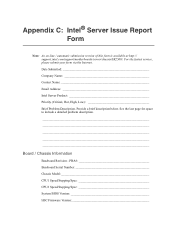
... Date Submitted Company Name Contact Name Email Address Intel Server Product Priority (Critical, Hot, High, Low Brief Problem Description. PBA Baseboard Serial Number Chassis Model CPU1 Speed/Stepping/Spec CPU2 Speed/Stepping/Spec System BIOS Version HSC Firmware Version See the last page for... space to include a detailed problem description Board / Chassis Information Baseboard Revision - Appendix C: Intel® Server Issue Report Form Note: An on-line /...
... Date Submitted Company Name Contact Name Email Address Intel Server Product Priority (Critical, Hot, High, Low Brief Problem Description. PBA Baseboard Serial Number Chassis Model CPU1 Speed/Stepping/Spec CPU2 Speed/Stepping/Spec System BIOS Version HSC Firmware Version See the last page for... space to include a detailed problem description Board / Chassis Information Baseboard Revision - Appendix C: Intel® Server Issue Report Form Note: An on-line /...