Service Guide
Page 3
... add and replace components on the Intel® Server System SR1690WB. Manual Organization Chapter 1 provides a list of this manual, see http://support.intel.com/ support/motherboards/server/S5500WB. Chapter 3 provides instructions on using the Intel® Server System SR1690WB. This manual is written for system technicians responsible for installing or replacing components such as the memory, processor, front panel board, and the...
... add and replace components on the Intel® Server System SR1690WB. Manual Organization Chapter 1 provides a list of this manual, see http://support.intel.com/ support/motherboards/server/S5500WB. Chapter 3 provides instructions on using the Intel® Server System SR1690WB. This manual is written for system technicians responsible for installing or replacing components such as the memory, processor, front panel board, and the...
Service Guide
Page 4
... series processors • DDR3 RDIMM/UDIMM Memory • Hard drive • Slimline CD-ROM or DVD-ROM drive • RAID controller add-in card iv Intel® Server System SR1690WB Service Guide Product Contents Your Intel® Server System SR1690WB ships with the following items: • Intel® Server Board S5500WB, installed in the server system • Chassis master assembly with the Intel® Server...
... series processors • DDR3 RDIMM/UDIMM Memory • Hard drive • Slimline CD-ROM or DVD-ROM drive • RAID controller add-in card iv Intel® Server System SR1690WB Service Guide Product Contents Your Intel® Server System SR1690WB ships with the following items: • Intel® Server Board S5500WB, installed in the server system • Chassis master assembly with the Intel® Server...
Service Guide
Page 5
• Operating system • For information about which accessories, memory, processors, and third-party hardware were tested and can be used with your board, and for ordering information for Intel products, see: http://support.intel.com/support/motherboards/server/ S5500WB/compat.htm Intel® Server System SR1690WB Service Guide v
• Operating system • For information about which accessories, memory, processors, and third-party hardware were tested and can be used with your board, and for ordering information for Intel products, see: http://support.intel.com/support/motherboards/server/ S5500WB/compat.htm Intel® Server System SR1690WB Service Guide v
Service Guide
Page 9
... Systems ...20 Hardware Requirements ...21 Processor ...21 Memory ...21 Memory Sparing and Mirroring 22 Power Supply ...23 Optional Hardware ...23 Intel® RAID Activation Key 23 Intel® Remote Management Module 3 23 Intel® I/O Expansion Module 24 Intel® Server System SR1690WB Service Guide ix Contents Preface ...iii About this Manual ...iii Manual Organization ...iii Product Contents ...iv Intel® Server System SR1690WB...
... Systems ...20 Hardware Requirements ...21 Processor ...21 Memory ...21 Memory Sparing and Mirroring 22 Power Supply ...23 Optional Hardware ...23 Intel® RAID Activation Key 23 Intel® Remote Management Module 3 23 Intel® I/O Expansion Module 24 Intel® Server System SR1690WB Service Guide ix Contents Preface ...iii About this Manual ...iii Manual Organization ...iii Product Contents ...iv Intel® Server System SR1690WB...

Service Guide
Page 10
... Intel® RMM 3 NIC 50 Installing the Intel® RMM3 and Intel® RMM3 NIC 50 Removing the Intel® RMM3 and Intel® RMM3 NIC 51 Replacing the Backplane Board 51 Removing the Backplane Board 52 Installing the Backplane Board 52 Replacing the Server Board 53 Removing the Server Board 53 Installing the Server Board 54 x Intel® Server System SR1690WB...
... Intel® RMM 3 NIC 50 Installing the Intel® RMM3 and Intel® RMM3 NIC 50 Removing the Intel® RMM3 and Intel® RMM3 NIC 51 Replacing the Backplane Board 51 Removing the Backplane Board 52 Installing the Backplane Board 52 Replacing the Server Board 53 Removing the Server Board 53 Installing the Server Board 54 x Intel® Server System SR1690WB...

Service Guide
Page 15
... Control Panel - Intel® Server System SR1690WB 17 Figure 9. Channel Slots Configuration 22 Figure 13. Installing the Server System Cover 27 Figure 15. Installing the Processor Air Duct 29 Figure 17. Locking the drive assembly 37 Figure 28. Removing the PCI Riser Assembly from the fans 46 Figure 37. Removing the backplane board 52 Intel® Server System SR1690WB Service Guide...
... Control Panel - Intel® Server System SR1690WB 17 Figure 9. Channel Slots Configuration 22 Figure 13. Installing the Server System Cover 27 Figure 15. Installing the Processor Air Duct 29 Figure 17. Locking the drive assembly 37 Figure 28. Removing the PCI Riser Assembly from the fans 46 Figure 37. Removing the backplane board 52 Intel® Server System SR1690WB Service Guide...
Service Guide
Page 19
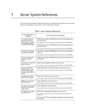
... you need to install it Intel® Server System SR1690WB Technical Product Specification can be found at: http://support.intel.com/support/motherboards/server/S5500WB/ Intel® Server System SR1690WB Technical Product Specification can be found at: http://support.intel.com/support/motherboards/server/S5500WB/ Intel® Server System SR1690WB Technical Product Specification Found at: http://support.intel.com/support/motherboards/server/S5500WB/ Intel® Server System SR1690WB Quick Start User's Guide...
... you need to install it Intel® Server System SR1690WB Technical Product Specification can be found at: http://support.intel.com/support/motherboards/server/S5500WB/ Intel® Server System SR1690WB Technical Product Specification can be found at: http://support.intel.com/support/motherboards/server/S5500WB/ Intel® Server System SR1690WB Technical Product Specification Found at: http://support.intel.com/support/motherboards/server/S5500WB/ Intel® Server System SR1690WB Quick Start User's Guide...
Service Guide
Page 22
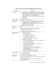
...; External I /O Expansion Modules. 4 Intel® Server System SR1690WB Service Guide One RMM3 connector to 95 W Thermal Design Power (TDP). • Supports future processor compatibility guidelines 4.8 GT/s, 5.86 GT/s, and 6.4 GT/s Intel® Quick Path Interconnect (Intel® QPI). Two connectors supporting double- Table 2. One low-profile USB 2x5 pin - Intel® Server System SR1690WB Feature Summary Feature Processor Memory Capacity Memory Type...
...; External I /O Expansion Modules. 4 Intel® Server System SR1690WB Service Guide One RMM3 connector to 95 W Thermal Design Power (TDP). • Supports future processor compatibility guidelines 4.8 GT/s, 5.86 GT/s, and 6.4 GT/s Intel® Quick Path Interconnect (Intel® QPI). Two connectors supporting double- Table 2. One low-profile USB 2x5 pin - Intel® Server System SR1690WB Feature Summary Feature Processor Memory Capacity Memory Type...

Service Guide
Page 27
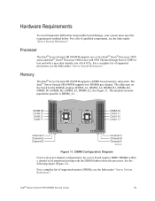
...; I /O AA. 4-pin Fan Connector (MEM2) F. Processor Socket 2 C. External I /O Expansion Module W. 8-pin CPU Connector Connectors B. USB Connector BB. 8-pin Fan Connector (MEM2R) Intel® Server System SR1690WB Service Guide 9 Remote Management Module 3 Y. 4-pin Fan Connector (CPU2) D. POST Code LEDs Z. 4-pin Fan Connector (CPU2A) E. Server Board Connector and Component Locations A B CD E F PP G OO H NN MM I LL KK J JJ...
...; I /O AA. 4-pin Fan Connector (MEM2) F. Processor Socket 2 C. External I /O Expansion Module W. 8-pin CPU Connector Connectors B. USB Connector BB. 8-pin Fan Connector (MEM2R) Intel® Server System SR1690WB Service Guide 9 Remote Management Module 3 Y. 4-pin Fan Connector (CPU2) D. POST Code LEDs Z. 4-pin Fan Connector (CPU2A) E. Server Board Connector and Component Locations A B CD E F PP G OO H NN MM I LL KK J JJ...

Service Guide
Page 28
.... USB Connector Q. 8-pin Fan Connector (MEM1R) MM. Serial Port B U. Server Board Connector and Component Locations 10 Intel® Server System SR1690WB Service Guide N/A FF. DIMM Slot A1 KK. N/A P. Battery CC. DIMM Slot E1 J. N/A V. DIMM Slot D2 H. Internal VGA Connector O. IMPB Connector T. 4-pin Fan Connector (CPU1) PP. Processor Socket 1 Figure 4. DIMM Slot C1 II. Low-Profile USB...
.... USB Connector Q. 8-pin Fan Connector (MEM1R) MM. Serial Port B U. Server Board Connector and Component Locations 10 Intel® Server System SR1690WB Service Guide N/A FF. DIMM Slot A1 KK. N/A P. Battery CC. DIMM Slot E1 J. N/A V. DIMM Slot D2 H. Internal VGA Connector O. IMPB Connector T. 4-pin Fan Connector (CPU1) PP. Processor Socket 1 Figure 4. DIMM Slot C1 II. Low-Profile USB...
Service Guide
Page 39
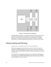
... with 95W Thermal Design Power (TDP) or less and with the DIMM farthest from the processor. Memory The Intel® Server System SR1690WB supports a DDR3-based memory subsystem. See Figure 11. For a complete list of supported processors, see the links under "Server System References". The silkscreen on the board for the DIMMs displays DIMM_A1, DIMM_A2, DIMM_B1, DIMM_B2, DIMM_D1...
... with 95W Thermal Design Power (TDP) or less and with the DIMM farthest from the processor. Memory The Intel® Server System SR1690WB supports a DDR3-based memory subsystem. See Figure 11. For a complete list of supported processors, see the links under "Server System References". The silkscreen on the board for the DIMMs displays DIMM_A1, DIMM_A2, DIMM_B1, DIMM_B2, DIMM_D1...
Service Guide
Page 40
... the data is the default Maximum Performance Mode preferred for mirroring. 22 Intel® Server System SR1690WB Service Guide With memory mirroring, the system maintains two copies of the installed DIMMs are used for Intel® Xeon® Processor 5500 series and Intel® Xeon® Processor 5600 series based platforms. All three channels may run at any order... mirrored copy of two DIMMs installed. If a DIMM fails, the data is not lost because the second copy of the data is not supported by Intel® Server System SR1690WB.
... the data is the default Maximum Performance Mode preferred for mirroring. 22 Intel® Server System SR1690WB Service Guide With memory mirroring, the system maintains two copies of the installed DIMMs are used for Intel® Xeon® Processor 5500 series and Intel® Xeon® Processor 5600 series based platforms. All three channels may run at any order... mirrored copy of two DIMMs installed. If a DIMM fails, the data is not lost because the second copy of the data is not supported by Intel® Server System SR1690WB.

Service Guide
Page 45
... proper airflow within the server system. For instructions, see "Removing the System Cover". 4. Installing the Server System Cover Removing and Installing the Processor Air Duct The system requires the use of this book. B A C DevOicpetical AF003223 Figure 14. See "Safety Information". 2. Lift the processor air duct from its location behind the two system blower fans. Intel® Server System SR1690WB Service Guide 27 Observe...
... proper airflow within the server system. For instructions, see "Removing the System Cover". 4. Installing the Server System Cover Removing and Installing the Processor Air Duct The system requires the use of this book. B A C DevOicpetical AF003223 Figure 14. See "Safety Information". 2. Lift the processor air duct from its location behind the two system blower fans. Intel® Server System SR1690WB Service Guide 27 Observe...

Service Guide
Page 46
Removing the Processor Air Duct Installing the Processor Air Duct 1. See "Safety Information". 2. For instructions, see "Removing the System Cover". 4. Lower the air duct into position. Power down the server and unplug all peripheral devices and the AC power cable. 3. Observe the safety and ESD precautions at the beginning of ... align the air duct side walls to pinch or disengage cables that may be near or under the air duct. 28 Intel® Server System SR1690WB Service Guide Remove the server system cover. Use caution not to the corresponding slots on the bracket behind the four...
Removing the Processor Air Duct Installing the Processor Air Duct 1. See "Safety Information". 2. For instructions, see "Removing the System Cover". 4. Lower the air duct into position. Power down the server and unplug all peripheral devices and the AC power cable. 3. Observe the safety and ESD precautions at the beginning of ... align the air duct side walls to pinch or disengage cables that may be near or under the air duct. 28 Intel® Server System SR1690WB Service Guide Remove the server system cover. Use caution not to the corresponding slots on the bracket behind the four...
Service Guide
Page 47
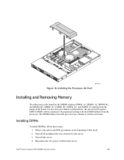
... at the beginning of the board. Turn off all peripheral devices connected to be populated starting from the inside of this book. 2. Turn off the server. 4. Intel® Server System SR1690WB Service Guide 29 DevOicpetical AF003225 Figure 16. The DIMM farthest from the processor per channel configurations, the server board requires DDR3 DIMMs within a channel to the...
... at the beginning of the board. Turn off all peripheral devices connected to be populated starting from the inside of this book. 2. Turn off the server. 4. Intel® Server System SR1690WB Service Guide 29 DevOicpetical AF003225 Figure 16. The DIMM farthest from the processor per channel configurations, the server board requires DDR3 DIMMs within a channel to the...
Service Guide
Page 49
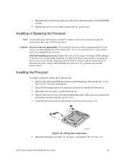
... connected to dissipate the static charge while handling the processor. (2) Avoid moving around unnecessarily. Remove the server's cover. Open the load plate (see Figure 18). 7. A B AF003228 Figure 18. Intel® Server System SR1690WB Service Guide 31 Observe the safety and ESD precautions at the beginning of compatible processor(s). Keep part of using the instructions that came with...
... connected to dissipate the static charge while handling the processor. (2) Avoid moving around unnecessarily. Remove the server's cover. Open the load plate (see Figure 18). 7. A B AF003228 Figure 18. Intel® Server System SR1690WB Service Guide 31 Observe the safety and ESD precautions at the beginning of compatible processor(s). Keep part of using the instructions that came with...
Service Guide
Page 50
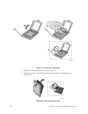
Take the processor out of the box and remove the protective shipping cover (Figure 20). Remove the socket protective cover (see Figure 19). 8. Removing the socket 32 Intel® Server System SR1690WB Service Guide AF003292 Figure 20. Open the Load Plate 7. A B AF003229 Figure 19.
Take the processor out of the box and remove the protective shipping cover (Figure 20). Remove the socket protective cover (see Figure 19). 8. Removing the socket 32 Intel® Server System SR1690WB Service Guide AF003292 Figure 20. Open the Load Plate 7. A B AF003229 Figure 19.
Service Guide
Page 51
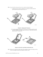
... to match the two socket pins, and then insert the processor into the socket as shown in package orientation and alignment with the socket: Intel® Server System SR1690WB Service Guide 33 To assist in Figure 21. B A AF003293 Figure 21. Close the Load Plate and Socket Lever Note: Make sure the alignment triangle mark ... and ensure the load plate tab engages under the socket lever when fully closed. (See letter "B" and "C" in Figure 22) A C B AF003294 Figure 22. Aligning the Processor 10. Note: Do not touch the socket pins;
... to match the two socket pins, and then insert the processor into the socket as shown in package orientation and alignment with the socket: Intel® Server System SR1690WB Service Guide 33 To assist in Figure 21. B A AF003293 Figure 21. Close the Load Plate and Socket Lever Note: Make sure the alignment triangle mark ... and ensure the load plate tab engages under the socket lever when fully closed. (See letter "B" and "C" in Figure 22) A C B AF003294 Figure 22. Aligning the Processor 10. Note: Do not touch the socket pins;

Service Guide
Page 52
... 2. Turn off all peripheral devices connected to reach the processor sockets. 8. Attach fan power cable to the white-circled numbers (see Figure 23). 5. IU Reference Heat sink Assembly 7. Replace the server's cover and reconnect the AC power cord. If a... See the documentation that came with your server chassis for correct airflow. Turn off the server. 34 Intel® Server System SR1690WB Service Guide Installing the Heat Sink(s) 1. Reinstall and reconnect any parts you removed or disconnected to the server. Replacing a Processor 1. Using a #2 Phillips* screwdriver, ...
... 2. Turn off all peripheral devices connected to reach the processor sockets. 8. Attach fan power cable to the white-circled numbers (see Figure 23). 5. IU Reference Heat sink Assembly 7. Replace the server's cover and reconnect the AC power cord. If a... See the documentation that came with your server chassis for correct airflow. Turn off the server. 34 Intel® Server System SR1690WB Service Guide Installing the Heat Sink(s) 1. Reinstall and reconnect any parts you removed or disconnected to the server. Replacing a Processor 1. Using a #2 Phillips* screwdriver, ...

Service Guide
Page 53
... of supported hardware. Pull out on the corners of supported hardware. 1. Intel® Server System SR1690WB Service Guide 35 Remove the AC power cord from the processor. Twist the heat sink slightly to maintain proper system cooling. Do not force the heat sink from the server. 4. Installing a SAS or SATA Hot-swap Hard Disk Drive Note: The...
... of supported hardware. Pull out on the corners of supported hardware. 1. Intel® Server System SR1690WB Service Guide 35 Remove the AC power cord from the processor. Twist the heat sink slightly to maintain proper system cooling. Do not force the heat sink from the server. 4. Installing a SAS or SATA Hot-swap Hard Disk Drive Note: The...