Service Guide
Page 3
... report form, troubleshooting information, regulatory information, and safety information. At the back of this chapter for installing rail kit to help you will find a list of the system features, photos of accessories or other components. Intel® Server System SR1680MV Service Guide iii In this chapter, you identify components and their locations. This document provides a brief...
... report form, troubleshooting information, regulatory information, and safety information. At the back of this chapter for installing rail kit to help you will find a list of the system features, photos of accessories or other components. Intel® Server System SR1680MV Service Guide iii In this chapter, you identify components and their locations. This document provides a brief...
Service Guide
Page 13
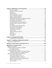
... the Rackmount Rail Kits 101 Procedure to install the rail kit 102 Appendix A: Intel® Server Issue Report Form 105 Appendix B: Troubleshooting 111 Resetting the System ...111 Problems following Initial System Installation 111 ...System Lights 113 Confirming Loading of the Operating System 113 Specific Problems and Corrective Actions 113 Power Light Does Not Light 113 No Characters Appear on Screen 114 Characters Are Distorted or Incorrect 114 System Cooling Fans Do Not Rotate Properly 115 Cannot Connect to a Server 115 LED Information ...116 Intel® Server System SR1680MV...
... the Rackmount Rail Kits 101 Procedure to install the rail kit 102 Appendix A: Intel® Server Issue Report Form 105 Appendix B: Troubleshooting 111 Resetting the System ...111 Problems following Initial System Installation 111 ...System Lights 113 Confirming Loading of the Operating System 113 Specific Problems and Corrective Actions 113 Power Light Does Not Light 113 No Characters Appear on Screen 114 Characters Are Distorted or Incorrect 114 System Cooling Fans Do Not Rotate Properly 115 Cannot Connect to a Server 115 LED Information ...116 Intel® Server System SR1680MV...

Service Guide
Page 18
...of Connectors and Pin 1 on I /O Board Module 37 Figure 44. Secure The Server Ears To Racks 104 xviii Intel® Server System SR1680MV Service Guide Lifting the PCI Cage from the I /O Board 44 Figure 53. Locations of Rail Kit 101 Figure 65. Connectors and Component Locations of NIC Board 50 Figure 57. ...103 Figure 69. Connecting the System Fan Cables 45 Figure 54. Connectors and Component Locations of 10 GB IO Card 52 Figure 59. Connectors and Components of Server Board 47 Figure 55. Location of MISC Jumper 56 Figure 63. Secure screw into the rail hole 103 Figure 67. ...
...of Connectors and Pin 1 on I /O Board Module 37 Figure 44. Secure The Server Ears To Racks 104 xviii Intel® Server System SR1680MV Service Guide Lifting the PCI Cage from the I /O Board 44 Figure 53. Locations of Rail Kit 101 Figure 65. Connectors and Component Locations of NIC Board 50 Figure 57. ...103 Figure 69. Connecting the System Fan Cables 45 Figure 54. Connectors and Component Locations of 10 GB IO Card 52 Figure 59. Connectors and Components of Server Board 47 Figure 55. Location of MISC Jumper 56 Figure 63. Secure screw into the rail hole 103 Figure 67. ...

Service Guide
Page 121
... different depths for racks are some recommended screwdrivers for this server. Reverse the instillation steps to remove the rail. The front overview and back overview of rail is shown below : Intel® Server System SR1680MV Service Guide 101 Spring secured in rail to secure each spring. Overview of Rail Kit Tighten Screw 1 Align Pin Tighten Screw 2 Spring Secure Screw...
... different depths for racks are some recommended screwdrivers for this server. Reverse the instillation steps to remove the rail. The front overview and back overview of rail is shown below : Intel® Server System SR1680MV Service Guide 101 Spring secured in rail to secure each spring. Overview of Rail Kit Tighten Screw 1 Align Pin Tighten Screw 2 Spring Secure Screw...

Service Guide
Page 122
The equipment rack must provide sufficient airflow to the system to install the rail kit Note: Please follow the steps below before you install the rail: 1. Figure 65. Procedure: 1. To avoid a potential electrical shock hazard, a third wire safety grounding conductor is necessary for Racks ... 707.0~719.5 mm Procedure to maintain proper cooling. Put the tighten screws2 into the hole of the rails (Recommended Driver Force: 5 lb-in). 102 Intel® Server System SR1680MV Service Guide Location Of Spring Screw Holes Table 45. Location and Adapt Depth for the rack installation. ...
The equipment rack must provide sufficient airflow to the system to install the rail kit Note: Please follow the steps below before you install the rail: 1. Figure 65. Procedure: 1. To avoid a potential electrical shock hazard, a third wire safety grounding conductor is necessary for Racks ... 707.0~719.5 mm Procedure to maintain proper cooling. Put the tighten screws2 into the hole of the rails (Recommended Driver Force: 5 lb-in). 102 Intel® Server System SR1680MV Service Guide Location Of Spring Screw Holes Table 45. Location and Adapt Depth for the rack installation. ...

Service Guide
Page 123
Figure 68. Position left and right rails at the desired 'U' position in ). Secure screw into the racks. Figure 67. Secure the Rail to the front and back of the racks using tighten screws1 and align pin (Recommended Driver Force 7 lb-in the racks. 4. Secure rails to Racks 5. Slide the server into the rail hole 3. Slide The Server Into Racks Intel® Server System SR1680MV Service Guide 103 Figure 66.
Figure 68. Position left and right rails at the desired 'U' position in ). Secure screw into the racks. Figure 67. Secure the Rail to the front and back of the racks using tighten screws1 and align pin (Recommended Driver Force 7 lb-in the racks. 4. Secure rails to Racks 5. Slide the server into the rail hole 3. Slide The Server Into Racks Intel® Server System SR1680MV Service Guide 103 Figure 66.

Service Guide
Page 124
Push the server to the end of racks to the racks. Tighten the thumbscrews to secure the ears of personal injury or damage to the rails. You must adequately support the system rack during installation and removal, or the risk of the server to let the server snap the springs. Figure 69. Secure The Server Ears To Racks Note: The system is not fixed to the rack or mounted to the equipment happens. 104 Intel® Server System SR1680MV Service Guide Figure 70. Push The Server To The End Of Racks 7. 6.
Push the server to the end of racks to the racks. Tighten the thumbscrews to secure the ears of personal injury or damage to the rails. You must adequately support the system rack during installation and removal, or the risk of the server to let the server snap the springs. Figure 69. Secure The Server Ears To Racks Note: The system is not fixed to the rack or mounted to the equipment happens. 104 Intel® Server System SR1680MV Service Guide Figure 70. Push The Server To The End Of Racks 7. 6.