Service Guide
Page 4
... functions of accessories or other components you must perform when installing or removing system components. Chapter 8 provides instructions for installing the necessary drivers for troubleshooting, upgrading, and repairing this manual, refer to the following Intel web site: http://support.intel.com/support/motherboards/server/SR1670HV/ Manual Organization Chapter 1 provides a brief overview of the embedded SATA RAID options...
... functions of accessories or other components you must perform when installing or removing system components. Chapter 8 provides instructions for installing the necessary drivers for troubleshooting, upgrading, and repairing this manual, refer to the following Intel web site: http://support.intel.com/support/motherboards/server/SR1670HV/ Manual Organization Chapter 1 provides a brief overview of the embedded SATA RAID options...

Service Guide
Page 5
... of drivers available) Operating System Driver (for an extensive list of the screen and select the option to search "This Product." For this product Processors that have been tested with your Intel server product. Software updates and additional information can be obtained at the following Intel web site: http://support.intel.com/support/motherboards/server/SR1670HV/ Unless otherwise indicated...
... of drivers available) Operating System Driver (for an extensive list of the screen and select the option to search "This Product." For this product Processors that have been tested with your Intel server product. Software updates and additional information can be obtained at the following Intel web site: http://support.intel.com/support/motherboards/server/SR1670HV/ Unless otherwise indicated...

Service Guide
Page 6
Jumpers, Connectors, and LEDs 35 5.1 Configuration and Support Jumpers 35 5.1.1 5.1.2 5.1.3 5.1.4 Clear RTC RAM (CLRTC1 35 VGA Controller Setting (3-pin VGA_SW1 36 DDR3 Voltage Control Setting (4-pin LVDDR3_SEL1, LVDDR3_SEL2) ...... 36 LAN Controller Setting (3-poin LAN_SW1, LAN_SW2 37 vi Intel® Server System SR1670HV Service Guide Hardware Setup 9 2.1 Chassis Cover...9 2.1.1 Removing the Chassis Cover 9 2.2 Central Processing Unit (CPU 9 2.2.1 Installing...
Jumpers, Connectors, and LEDs 35 5.1 Configuration and Support Jumpers 35 5.1.1 5.1.2 5.1.3 5.1.4 Clear RTC RAM (CLRTC1 35 VGA Controller Setting (3-pin VGA_SW1 36 DDR3 Voltage Control Setting (4-pin LVDDR3_SEL1, LVDDR3_SEL2) ...... 36 LAN Controller Setting (3-poin LAN_SW1, LAN_SW2 37 vi Intel® Server System SR1670HV Service Guide Hardware Setup 9 2.1 Chassis Cover...9 2.1.1 Removing the Chassis Cover 9 2.2 Central Processing Unit (CPU 9 2.2.1 Installing...

Service Guide
Page 14
System Feature Set ...1 Table 3. Server Node Connectors and Components Descriptions 6 Table 4. Maximum Memory Allocation Using RDIMMs 16 Table 8. Supported RDIMM Configurations 17 Table 9. System Package Contents List 1 Table 2. RJ-45 Ports 1 and 2 LEDs Descriptions 7 Table 6. Front Panel LEDs Descriptions 6 Table 5. Memory Population Table 18 xiv Intel® Server System SR1670HV Service Guide HDD LED Status Definitions 7 Table 7. List of Tables List of Tables Table 1. Supported UDIMM Configurations 17 Table 10.
System Feature Set ...1 Table 3. Server Node Connectors and Components Descriptions 6 Table 4. Maximum Memory Allocation Using RDIMMs 16 Table 8. Supported RDIMM Configurations 17 Table 9. System Package Contents List 1 Table 2. RJ-45 Ports 1 and 2 LEDs Descriptions 7 Table 6. Front Panel LEDs Descriptions 6 Table 5. Memory Population Table 18 xiv Intel® Server System SR1670HV Service Guide HDD LED Status Definitions 7 Table 7. List of Tables List of Tables Table 1. Supported UDIMM Configurations 17 Table 10.
Service Guide
Page 16
... ƒ 2 x BMC Management Modules Documentation & Software ƒ Attention Document ƒ Intel Resource CD 1.2 System Features The Intel® Server System SR1670HV is a 1U rackmount server integrating two, ½-width Intel® Server System Boards S5500HV. Product Introduction 1. Intel® Server System SR1670HV Service Guide 1 The server supports the Intel® Xeon® processor 5500 series, 5600 series and Intel® 5500 chipset, and provides the following items. Table 1.
... ƒ 2 x BMC Management Modules Documentation & Software ƒ Attention Document ƒ Intel Resource CD 1.2 System Features The Intel® Server System SR1670HV is a 1U rackmount server integrating two, ½-width Intel® Server System Boards S5500HV. Product Introduction 1. Intel® Server System SR1670HV Service Guide 1 The server supports the Intel® Xeon® processor 5500 series, 5600 series and Intel® 5500 chipset, and provides the following items. Table 1.

Service Guide
Page 17
...-in cards (one per server node) Video Storage Power Supply Networking Server Management System Dimensions On-board ASPEED* AST2050 with integrated Video Controller ƒ Integrated 2D Video Controller ƒ 8 MB Video Memory 8 x 2.5-inch hot-swap SATA Hard Drive Bays (Four drive bays per server node) Embedded support for the following RAID solutions: ƒ Intel® Matrix Storage...
...-in cards (one per server node) Video Storage Power Supply Networking Server Management System Dimensions On-board ASPEED* AST2050 with integrated Video Controller ƒ Integrated 2D Video Controller ƒ 8 MB Video Memory 8 x 2.5-inch hot-swap SATA Hard Drive Bays (Four drive bays per server node) Embedded support for the following RAID solutions: ƒ Intel® Matrix Storage...

Service Guide
Page 28
... as shown. The heatsink has Thermal Interface Material (TIM) located on the bottom of 8 inch-pounds torque. To install the heatsink, follows these steps: 1. Intel® Server System SR1670HV Service Guide 13 Hardware Setup Figure 17. Pay close attention to provide correct airflow through 4c by giving it two rotations in the clockwise direction... corners in the captive screws on the heatsink to a maximum of it two rotations and stop. Orient the heatsink over the processor, lining up to support processor cooling. c.
... as shown. The heatsink has Thermal Interface Material (TIM) located on the bottom of 8 inch-pounds torque. To install the heatsink, follows these steps: 1. Intel® Server System SR1670HV Service Guide 13 Hardware Setup Figure 17. Pay close attention to provide correct airflow through 4c by giving it two rotations in the clockwise direction... corners in the captive screws on the heatsink to a maximum of it two rotations and stop. Orient the heatsink over the processor, lining up to support processor cooling. c.
Service Guide
Page 30
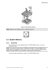
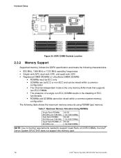
... in single processor configurations. Intel® Server System SR1670HV Service Guide 15 NOTE: You should only install memory in DIMM sockets DIMM_D1 through DIMM_F2 are installed on a given server node. On a given server node, DIMM sockets DIMM_D1 through DIMM_F2 when dual processors are not enabled in a diagonal sequence. 2.3 System Memory 2.3.1 Overview Each installed server node supports twelve (12) DDR3...
... in single processor configurations. Intel® Server System SR1670HV Service Guide 15 NOTE: You should only install memory in DIMM sockets DIMM_D1 through DIMM_F2 are installed on a given server node. On a given server node, DIMM sockets DIMM_D1 through DIMM_F2 when dual processors are not enabled in a diagonal sequence. 2.3 System Memory 2.3.1 Overview Each installed server node supports twelve (12) DDR3...
Service Guide
Page 31
...within a common configuration ƒ The Channel Independent mode is the only memory RAS mode that supports non-ECC DIMMs. ƒ The presence of a single non-ECC UDIMM results in the... disabling of ECC functionality. ƒ RDIMMs and UDIMMs cannot be mixed within a common system memory configuration The following table shows the maximum memory amounts using RDIMM type memory: Table 7. ...: Due to thermal requirements needed to support Quad Rank x4 DDR3 DIMMs, the Intel® Server System SR1670HV does not support this memory type. 16 Intel® Server System SR1670HV Service Guide
...within a common configuration ƒ The Channel Independent mode is the only memory RAS mode that supports non-ECC DIMMs. ƒ The presence of a single non-ECC UDIMM results in the... disabling of ECC functionality. ƒ RDIMMs and UDIMMs cannot be mixed within a common system memory configuration The following table shows the maximum memory amounts using RDIMM type memory: Table 7. ...: Due to thermal requirements needed to support Quad Rank x4 DDR3 DIMMs, the Intel® Server System SR1670HV does not support this memory type. 16 Intel® Server System SR1670HV Service Guide

Service Guide
Page 32
... Populated per Channel 1 Unbuffered DDR3 800, SR or DR (with ECC; No RAS support for non-ECC UDIMMs. No x4 SDDC support with UDIMM with or without 1066 ECC) Does NOT support 256 Mb, 512 Mb, and 4 Gb DRAM technologies; Intel® Server System SR1670HV Service Guide 17 Any combination of x8 UDIMMs with 1 Gb or 2 Gb DRAM Density...
... Populated per Channel 1 Unbuffered DDR3 800, SR or DR (with ECC; No RAS support for non-ECC UDIMMs. No x4 SDDC support with UDIMM with or without 1066 ECC) Does NOT support 256 Mb, 512 Mb, and 4 Gb DRAM technologies; Intel® Server System SR1670HV Service Guide 17 Any combination of x8 UDIMMs with 1 Gb or 2 Gb DRAM Density...

Service Guide
Page 34
... fingers when pressing the retaining clips. Remove the DIMM from the socket. Intel® Server System SR1670HV Service Guide 19 Figure 22. Figure 23. Simultaneously press the retaining clips on each side of the DIMM outward to remove a DIMM: 1. DIMM Notch NOTE: Support the DIMM lightly with extra force. 2. The DIMM might get damaged when...
... fingers when pressing the retaining clips. Remove the DIMM from the socket. Intel® Server System SR1670HV Service Guide 19 Figure 22. Figure 23. Simultaneously press the retaining clips on each side of the DIMM outward to remove a DIMM: 1. DIMM Notch NOTE: Support the DIMM lightly with extra force. 2. The DIMM might get damaged when...

Service Guide
Page 38
... 5. When inserted into a drive bay until it with the bay edge. Placing a SATAII/SAS Hard Disk Drive on the server board. Intel® Server System SR1670HV Service Guide 23 Each installed hard disk is correctly placed when its front edge aligns with its four screws. The drive tray ejects...spring lock to a matching SATA port number on the Tray 4. Hardware Setup 2.6 Hard Disk Drives The system supports up to eight hot-swap 2.5-inch SATAII/SAS hard disk drives-four for each server node are numbered as follows: 3 4 2 1 Figure 31. Hard Disk Drives Each drive number corresponds...
... 5. When inserted into a drive bay until it with the bay edge. Placing a SATAII/SAS Hard Disk Drive on the server board. Intel® Server System SR1670HV Service Guide 23 Each installed hard disk is correctly placed when its front edge aligns with its four screws. The drive tray ejects...spring lock to a matching SATA port number on the Tray 4. Hardware Setup 2.6 Hard Disk Drives The system supports up to eight hot-swap 2.5-inch SATAII/SAS hard disk drives-four for each server node are numbered as follows: 3 4 2 1 Figure 31. Hard Disk Drives Each drive number corresponds...

Service Guide
Page 50
..., and then move the jumper again to clear the CMOS RTC RAM data. Clear RTC RAM Intel® Server System SR1670HV Service Guide 35 Turn OFF the computer and unplug the power cord. 2. Removing the cap causes system boot failure! After the CMOS clearance, reinstall the battery. Figure ...RAM: 1. Move the jumper cap from pins 1-2 (default) to re-enter data. Jumpers, Connectors, and LEDs 5. Jumpers, Connectors, and LEDs 5.1 Configuration and Support Jumpers 5.1.1 Clear RTC RAM (CLRTC1) This jumper allows you to pins 1-2. 3. You can clear the CMOS memory of date, time, and system...
..., and then move the jumper again to clear the CMOS RTC RAM data. Clear RTC RAM Intel® Server System SR1670HV Service Guide 35 Turn OFF the computer and unplug the power cord. 2. Removing the cap causes system boot failure! After the CMOS clearance, reinstall the battery. Figure ...RAM: 1. Move the jumper cap from pins 1-2 (default) to re-enter data. Jumpers, Connectors, and LEDs 5. Jumpers, Connectors, and LEDs 5.1 Configuration and Support Jumpers 5.1.1 Clear RTC RAM (CLRTC1) This jumper allows you to pins 1-2. 3. You can clear the CMOS memory of date, time, and system...

Service Guide
Page 51
... Intel® Server System SR1670HV Service Guide CAUTION Moving these jumpers from their functionality. Set to pins 1-2 to select 1.5V BIOS control, pins 2-3 to select 1.2V Force or 3-4 to activate the VGA feature. This document will only be updated with full usage information once validation is intended for future use only, and will be supported...
... Intel® Server System SR1670HV Service Guide CAUTION Moving these jumpers from their functionality. Set to pins 1-2 to select 1.5V BIOS control, pins 2-3 to select 1.2V Force or 3-4 to activate the VGA feature. This document will only be updated with full usage information once validation is intended for future use only, and will be supported...

Service Guide
Page 54
... the back of data transfer rate. Jumpers, Connectors, and LEDs 5.2 Server Board Connectors 5.2.1 Serial ATA Connectors (7-pin SATA1, SATA2, SATA3, SATA4) Supported by the Intel® ICH10R chipset, these connectors are for Serial ATA hard disk drives that allow up to 480 Mbps connection speed. USB 2.0 Connectors Intel® Server System SR1670HV Service Guide 39 Figure 65.
... the back of data transfer rate. Jumpers, Connectors, and LEDs 5.2 Server Board Connectors 5.2.1 Serial ATA Connectors (7-pin SATA1, SATA2, SATA3, SATA4) Supported by the Intel® ICH10R chipset, these connectors are for Serial ATA hard disk drives that allow up to 480 Mbps connection speed. USB 2.0 Connectors Intel® Server System SR1670HV Service Guide 39 Figure 65.

Service Guide
Page 55
CAUTION DO NOT forget to connect the fan cables to the fan connectors on the server board, ensuring the black wire of each cable matches the ground pin of 3.15 A-6.66 A (53.28 W max.) at +12V. ...Serial General Purpose I/O Connector 40 Intel® Server System SR1670HV Service Guide Insufficient air flow inside the system may damage the server board components. Connect the fan cables to the fan connectors. Jumpers, Connectors, and LEDs 5.2.3 System Fan Connectors (4-pin FRNT_FAN1, FRNT_FAN2, FRNT_FAN3, FRNT_FAN4) The system fan connectors support cooling fans of 350 mA-740...
CAUTION DO NOT forget to connect the fan cables to the fan connectors on the server board, ensuring the black wire of each cable matches the ground pin of 3.15 A-6.66 A (53.28 W max.) at +12V. ...Serial General Purpose I/O Connector 40 Intel® Server System SR1670HV Service Guide Insufficient air flow inside the system may damage the server board components. Connect the fan cables to the fan connectors. Jumpers, Connectors, and LEDs 5.2.3 System Fan Connectors (4-pin FRNT_FAN1, FRNT_FAN2, FRNT_FAN3, FRNT_FAN4) The system fan connectors support cooling fans of 350 mA-740...
Service Guide
Page 56
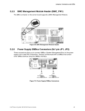
Figure 70. Jumpers, Connectors, and LEDs 5.2.5 BMC Management Module Header (BMC_FW1) The BMC connector on the server board supports a BMC Management Module. Power Supply SMBus Connectors Intel® Server System SR1670HV Service Guide 41 BMC Management Module Header 5.2.6 Power Supply SMBus Connectors (6x1 pin JP1, JP2) These connectors allow you to connect SMBus (System Management Bus) to the power supply unit to read PSU information. Figure 69. Devices communicate with a SMBus host and/or other SMBus devices using the SMBus interface.
Figure 70. Jumpers, Connectors, and LEDs 5.2.5 BMC Management Module Header (BMC_FW1) The BMC connector on the server board supports a BMC Management Module. Power Supply SMBus Connectors Intel® Server System SR1670HV Service Guide 41 BMC Management Module Header 5.2.6 Power Supply SMBus Connectors (6x1 pin JP1, JP2) These connectors allow you to connect SMBus (System Management Bus) to the power supply unit to read PSU information. Figure 69. Devices communicate with a SMBus host and/or other SMBus devices using the SMBus interface.

Service Guide
Page 57
.... Both connectors have identical pin-outs and are not used concurrently. Figure 71. Peripheral Power Connector (4-pin PWR3) 5.2.9 System Panel Connector (20-pin PANEL1) This connector supports several chassis-mounted functions. 42 Intel® Server System SR1670HV Service Guide This connector has the following pin-out and board location: +12 V GND GND +5V Figure 72. Main...
.... Both connectors have identical pin-outs and are not used concurrently. Figure 71. Peripheral Power Connector (4-pin PWR3) 5.2.9 System Panel Connector (20-pin PANEL1) This connector supports several chassis-mounted functions. 42 Intel® Server System SR1670HV Service Guide This connector has the following pin-out and board location: +12 V GND GND +5V Figure 72. Main...

Service Guide
Page 62
...used to best meet custom operating environments. Extract files from the BIOS Update Package to boot from Intel at the following web site: http://support.intel.com/support/motherboards/server/SR1670HV/ The System Update or BIOS Update package includes the following procedure to configure the USB Flash Drive as the ...for instructions on how to enhance features or correct reported issues. See BIOS Setup later in the system. Intel® Server System SR1670HV Service Guide 47 See the BIOS Setup Utility section later for this utility. This section describes how to keep your...
...used to best meet custom operating environments. Extract files from the BIOS Update Package to boot from Intel at the following web site: http://support.intel.com/support/motherboards/server/SR1670HV/ The System Update or BIOS Update package includes the following procedure to configure the USB Flash Drive as the ...for instructions on how to enhance features or correct reported issues. See BIOS Setup later in the system. Intel® Server System SR1670HV Service Guide 47 See the BIOS Setup Utility section later for this utility. This section describes how to keep your...

Service Guide
Page 63
.... If your BIOS becomes corrupted for the changes to pins 2-3. 48 Intel® Server System SR1670HV Service Guide Updating the BIOS in the following Intel Web Site http://support.intel.com/support/motherboards/server/SR1670HV/ 2. Save the BIOS Settings and reboot server. 6.2 BIOS Recovery Process In the unlikely event your system from the update package to reset BIOS defaults. 7. BIOS Updates and...
.... If your BIOS becomes corrupted for the changes to pins 2-3. 48 Intel® Server System SR1670HV Service Guide Updating the BIOS in the following Intel Web Site http://support.intel.com/support/motherboards/server/SR1670HV/ 2. Save the BIOS Settings and reboot server. 6.2 BIOS Recovery Process In the unlikely event your system from the update package to reset BIOS defaults. 7. BIOS Updates and...