Service Guide
Page 4
.... Chapter 2 lists the hardware setup procedures you for different system components. Chapter 6 describes the update process and configurable features of the system BIOS Chapter 7 provides an overview of the Intel® Server System SR1670HV. Chapter 11 details product safety information. In this server system. Chapter 5 describes the functions of the system features, product photos, and product diagrams to configure RAID...
.... Chapter 2 lists the hardware setup procedures you for different system components. Chapter 6 describes the update process and configurable features of the system BIOS Chapter 7 provides an overview of the Intel® Server System SR1670HV. Chapter 11 details product safety information. In this server system. Chapter 5 describes the functions of the system features, product photos, and product diagrams to configure RAID...

Service Guide
Page 5
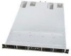
... the following Intel web site: http://support.intel.com/support/motherboards/server/SR1670HV/ Unless otherwise indicated in -depth technical information about this product For information needed to search "This Product." Software updates and additional information can be obtained at the left side of drivers available) Operating System Driver (for operating system drivers) Firmware Update Intel® Server System SR1670HV Service...
... the following Intel web site: http://support.intel.com/support/motherboards/server/SR1670HV/ Unless otherwise indicated in -depth technical information about this product For information needed to search "This Product." Software updates and additional information can be obtained at the left side of drivers available) Operating System Driver (for operating system drivers) Firmware Update Intel® Server System SR1670HV Service...

Service Guide
Page 7
... 8.5.1 Running the Resource CD 105 8.5.2 Drivers Menu 105 8.5.3 Utilities Menu 106 8.5.4 Make Disk Menu 106 Intel® Server System SR1670HV Service Guide vii Contents 5.1.5 Intel® ICH10R SATA Port SW RAID Setting (3-pin RAID_SEL1 37 5.1.6 Force BIOS Recovery Setting (3-pin RECOVERY1 38 5.2 Server Board Connectors 39 5.2.1 Serial ATA Connectors (7-pin SATA1, SATA2, SATA3, SATA4 39 5.2.2 Internal USB...
... 8.5.1 Running the Resource CD 105 8.5.2 Drivers Menu 105 8.5.3 Utilities Menu 106 8.5.4 Make Disk Menu 106 Intel® Server System SR1670HV Service Guide vii Contents 5.1.5 Intel® ICH10R SATA Port SW RAID Setting (3-pin RAID_SEL1 37 5.1.6 Force BIOS Recovery Setting (3-pin RECOVERY1 38 5.2 Server Board Connectors 39 5.2.1 Serial ATA Connectors (7-pin SATA1, SATA2, SATA3, SATA4 39 5.2.2 Internal USB...

Service Guide
Page 11
...Figure 53. Clear RTC RAM...35 Figure 60. SATA Connectors ...39 Figure 66. Serial General Purpose I/O Connector 40 Figure 69. Power Supply SMBus Connectors 41 Figure 71. System Panel Connector 43 Figure 74. BIOS Menu Screen...50 Figure 82. System Memory Information Menu 56 ...Figure 90. Chipset Configuration Menu 61 Figure 94. South Bridge Chipset Configuration Menu 64 Intel® Server System SR1670HV Service Guide xi Screws On Hard...
...Figure 53. Clear RTC RAM...35 Figure 60. SATA Connectors ...39 Figure 66. Serial General Purpose I/O Connector 40 Figure 69. Power Supply SMBus Connectors 41 Figure 71. System Panel Connector 43 Figure 74. BIOS Menu Screen...50 Figure 82. System Memory Information Menu 56 ...Figure 90. Chipset Configuration Menu 61 Figure 94. South Bridge Chipset Configuration Menu 64 Intel® Server System SR1670HV Service Guide xi Screws On Hard...

Service Guide
Page 32
... 800, SR or DR (with the blue slot farthest from the CPU. ƒ All channels in a system will run in the same channel, the BIOS will flag this server system, Intel does not plan to 1066 MHz. No RAS support for non-ECC UDIMMs. No x4 SDDC support with UDIMM...two 1333 MHz-capable UDIMMs or RDIMMs is mixed with or without 1066, ECC) 1333 1. Intel® Server System SR1670HV Service Guide 17 When installing memory, consider the following: ƒ Populate DIMMs by channel starting with or without 1066 ECC) Does NOT support 256 Mb, 512 Mb, and 4 Gb DRAM technologies; Table 9.
... 800, SR or DR (with the blue slot farthest from the CPU. ƒ All channels in a system will run in the same channel, the BIOS will flag this server system, Intel does not plan to 1066 MHz. No RAS support for non-ECC UDIMMs. No x4 SDDC support with UDIMM...two 1333 MHz-capable UDIMMs or RDIMMs is mixed with or without 1066, ECC) 1333 1. Intel® Server System SR1670HV Service Guide 17 When installing memory, consider the following: ƒ Populate DIMMs by channel starting with or without 1066 ECC) Does NOT support 256 Mb, 512 Mb, and 4 Gb DRAM technologies; Table 9.

Service Guide
Page 50
...battery powers the RAM data in the power cord and turn ON the computer. 4. Plug in CMOS, which includes system setup information such as system passwords. After the CMOS clearance, reinstall the battery. Hold down the key during the boot process and enter the BIOS setup to pins... to re-enter data. Figure 59. Removing the cap causes system boot failure! To erase the RTC RAM: 1. Move the jumper cap from pins 1-2 (default) to clear the CMOS RTC RAM data. Clear RTC RAM Intel® Server System SR1670HV Service Guide 35 Jumpers, Connectors, and LEDs 5.1 Configuration and ...
...battery powers the RAM data in the power cord and turn ON the computer. 4. Plug in CMOS, which includes system setup information such as system passwords. After the CMOS clearance, reinstall the battery. Hold down the key during the boot process and enter the BIOS setup to pins... to re-enter data. Figure 59. Removing the cap causes system boot failure! To erase the RTC RAM: 1. Move the jumper cap from pins 1-2 (default) to clear the CMOS RTC RAM data. Clear RTC RAM Intel® Server System SR1670HV Service Guide 35 Jumpers, Connectors, and LEDs 5.1 Configuration and ...

Service Guide
Page 51
...only be changed when low voltage DDR3 DIMMs are added to enable or disable the onboard VGA controller. Set to pins 1-2 to select 1.5V BIOS control, pins 2-3 to select 1.2V Force or 3-4 to activate the VGA feature. Set to pins 1-2 to select 1.35V Force. VGA ...be updated with full usage information once validation is intended for each CPU bank of LV (low voltage) DDR3 DIMMs on this server board. 36 Intel® Server System SR1670HV Service Guide CAUTION Moving these jumpers from their functionality. Jumpers, Connectors, and LEDs 5.1.2 VGA Controller Setting (3-pin VGA_SW1) This...
...only be changed when low voltage DDR3 DIMMs are added to enable or disable the onboard VGA controller. Set to pins 1-2 to select 1.5V BIOS control, pins 2-3 to select 1.2V Force or 3-4 to activate the VGA feature. Set to pins 1-2 to select 1.35V Force. VGA ...be updated with full usage information once validation is intended for each CPU bank of LV (low voltage) DDR3 DIMMs on this server board. 36 Intel® Server System SR1670HV Service Guide CAUTION Moving these jumpers from their functionality. Jumpers, Connectors, and LEDs 5.1.2 VGA Controller Setting (3-pin VGA_SW1) This...

Service Guide
Page 53
... (XXXXXX.ROM) and the AFUDOS.EXE utility. 2. Force BIOS Recovery Setting 38 Intel® Server System SR1670HV Service Guide Set the jumper back to pins 2-3. 3. Set the jumper to pins 1-2. 6. Insert the USB flash and turn on the system. Turn on the system to quickly update or recover the BIOS settings when it becomes corrupted. Shut down the...
... (XXXXXX.ROM) and the AFUDOS.EXE utility. 2. Force BIOS Recovery Setting 38 Intel® Server System SR1670HV Service Guide Set the jumper back to pins 2-3. 3. Set the jumper to pins 1-2. 6. Insert the USB flash and turn on the system. Turn on the system to quickly update or recover the BIOS settings when it becomes corrupted. Shut down the...

Service Guide
Page 58
...System warning speaker (4-pin SPEAKER) This 4-pin connector is for the chassis-mounted system warning speaker. Intel® Server System SR1670HV Service Guide 43 System Panel Connector 5.2.9.1 System power LED (3-pin PLED) This 3-pin connector is for system... reboot without turning off button (2-pin PWRSW) This connector is for the system... four seconds while the system is ON turns the system OFF. 5.2.9.6 Reset button...
...System warning speaker (4-pin SPEAKER) This 4-pin connector is for the chassis-mounted system warning speaker. Intel® Server System SR1670HV Service Guide 43 System Panel Connector 5.2.9.1 System power LED (3-pin PLED) This 3-pin connector is for system... reboot without turning off button (2-pin PWRSW) This connector is for the system... four seconds while the system is ON turns the system OFF. 5.2.9.6 Reset button...

Service Guide
Page 62
... change. 3. Intel® Server System SR1670HV Service Guide 47 You should complete the following files: ƒ AFUDOS.EXE - At the DOS prompt, type the name of its options. 6.1 Updating System BIOS Periodically, Intel makes available a new BIOS release for instructions on how to update the BIOS by the AFUDOS utility. ƒ BIOS##.BAT - NOTE: Prior to updating the System BIOS, Intel recommends reading...
... change. 3. Intel® Server System SR1670HV Service Guide 47 You should complete the following files: ƒ AFUDOS.EXE - At the DOS prompt, type the name of its options. 6.1 Updating System BIOS Periodically, Intel makes available a new BIOS release for instructions on how to update the BIOS by the AFUDOS utility. ƒ BIOS##.BAT - NOTE: Prior to updating the System BIOS, Intel recommends reading...

Service Guide
Page 63
... the root directory of a DOS bootable USB Flash Drive. 3. Remove the system top cover. 4. At the Main Menu Screen, press the key to pins 2-3. 48 Intel® Server System SR1670HV Service Guide BIOS Updates and Configuration Figure 79. Doing so corrupts the BIOS and prevents your system from the update package to take effect. 5. Extract all the files...
... the root directory of a DOS bootable USB Flash Drive. 3. Remove the system top cover. 4. At the Main Menu Screen, press the key to pins 2-3. 48 Intel® Server System SR1670HV Service Guide BIOS Updates and Configuration Figure 79. Doing so corrupts the BIOS and prevents your system from the update package to take effect. 5. Extract all the files...

Service Guide
Page 64
Set the Force BIOS Update jumper back to load BIOS Setting Defaults. 11. Power on the system. The BIOS update process begins automatically. 6. BIOS Updates and Configuration Figure 80. Recovering the BIOS Using the Force BIOS Update Jumper 5. This section provides an overview of server configuration make changes to meet the needs of the server. Intel® Server System SR1670HV Service Guide 49 Plug...
Set the Force BIOS Update jumper back to load BIOS Setting Defaults. 11. Power on the system. The BIOS update process begins automatically. 6. BIOS Updates and Configuration Figure 80. Recovering the BIOS Using the Force BIOS Update Jumper 5. This section provides an overview of server configuration make changes to meet the needs of the server. Intel® Server System SR1670HV Service Guide 49 Plug...

Service Guide
Page 65
... or left arrow keys until the menu you can alter system behavior to an undesired state. 50 Intel® Server System SR1670HV Service Guide Advanced: Provides several sub-menus used to the server. Making uninformed changes can access the BIOS Setup Utility. 6.3.2 BIOS Setup Features and Navigation The BIOS Setup Utility is booting up, the screen will display when...
... or left arrow keys until the menu you can alter system behavior to an undesired state. 50 Intel® Server System SR1670HV Service Guide Advanced: Provides several sub-menus used to the server. Making uninformed changes can access the BIOS Setup Utility. 6.3.2 BIOS Setup Features and Navigation The BIOS Setup Utility is booting up, the screen will display when...

Service Guide
Page 66
... Utility, the Main menu screen displays, providing options to view basic system information and view/configure any SATA devices detected. Intel® Server System SR1670HV Service Guide 51 BIOS Updates and Configuration Server: Provides sub-menus used to view/change system boot options and system security. These fields are items that particular menu. A scroll bar displays on the right...
... Utility, the Main menu screen displays, providing options to view basic system information and view/configure any SATA devices detected. Intel® Server System SR1670HV Service Guide 51 BIOS Updates and Configuration Server: Provides sub-menus used to view/change system boot options and system security. These fields are items that particular menu. A scroll bar displays on the right...

Service Guide
Page 67
... These fields display devices that the BIOS has obtained directly from the device, and may include the following: Device Type, Vendor, Size, LBA Mode, Block 52 Intel® Server System SR1670HV Service Guide Main Menu 6.3.3.1 System Time [xx/xx/xxxx] This option displays and gives the option to change the system time. 6.3.3.2 System Date [Day xx/xx/xxxx...
... These fields display devices that the BIOS has obtained directly from the device, and may include the following: Device Type, Vendor, Size, LBA Mode, Block 52 Intel® Server System SR1670HV Service Guide Main Menu 6.3.3.1 System Time [xx/xx/xxxx] This option displays and gives the option to change the system time. 6.3.3.2 System Date [Day xx/xx/xxxx...

Service Guide
Page 68
...: [Disabled] [Enabled] 6.3.3.4 IDE Configuration Sub-Menu The items in the system. BIOS Updates and Configuration Mode, PIO Mode, Async DMA, Ultra DMA, and S.M.A.R.T. Setting to select the data transfer mode. Configuration options: [Auto] [0] [1] [2] [3] [4] 6.3.3.3.4 DMA Mode [Auto] Sets the DMA mode. Intel® Server System SR1670HV Service Guide 53 Select an item then press if you to...
...: [Disabled] [Enabled] 6.3.3.4 IDE Configuration Sub-Menu The items in the system. BIOS Updates and Configuration Mode, PIO Mode, Async DMA, Ultra DMA, and S.M.A.R.T. Setting to select the data transfer mode. Configuration options: [Auto] [0] [1] [2] [3] [4] 6.3.3.3.4 DMA Mode [Auto] Sets the DMA mode. Intel® Server System SR1670HV Service Guide 53 Select an item then press if you to...

Service Guide
Page 69
...as [IDE] Sets the configuration for detecting ATA/ATAPI devices. This is effective only if the device is the section for AHCI configuration. 54 Intel® Server System SR1670HV Service Guide IDE Configuration Menu 6.3.3.4.1 SATA Configuration [Enhanced] Configuration options: [Disabled] [Compatible] [Enhanced] Configure SATA as Parallel ATA physical storage devices... device write protection. Configuration options: [0] [5] [10] [15] [20] [25] [30] [35] 6.3.3.5 AHCI Configuration Sub-Menu This menu is accessed through the BIOS. BIOS Updates and Configuration Figure 85.
...as [IDE] Sets the configuration for detecting ATA/ATAPI devices. This is effective only if the device is the section for AHCI configuration. 54 Intel® Server System SR1670HV Service Guide IDE Configuration Menu 6.3.3.4.1 SATA Configuration [Enhanced] Configuration options: [Disabled] [Compatible] [Enhanced] Configure SATA as Parallel ATA physical storage devices... device write protection. Configuration options: [0] [5] [10] [15] [20] [25] [30] [35] 6.3.3.5 AHCI Configuration Sub-Menu This menu is accessed through the BIOS. BIOS Updates and Configuration Figure 85.

Service Guide
Page 70
Figure 87. BIOS Updates and Configuration Figure 86. Configuration options: [Disabled] [Enabled] Intel® Server System SR1670HV Service Guide 55 AHCI Configuration Menu 6.3.3.5.1 AHCI CD/DVD Boot Time out [35] Selects the boot time out value for SATA CD/DVD devices in ... connected to set the Self-Monitoring, Analysis and Reporting Technology. Status of Auto-Detection of SATA Devices Menu 6.3.3.5.3 SATA Port0 [Auto] Allows you to the system.
Figure 87. BIOS Updates and Configuration Figure 86. Configuration options: [Disabled] [Enabled] Intel® Server System SR1670HV Service Guide 55 AHCI Configuration Menu 6.3.3.5.1 AHCI CD/DVD Boot Time out [35] Selects the boot time out value for SATA CD/DVD devices in ... connected to set the Self-Monitoring, Analysis and Reporting Technology. Status of Auto-Detection of SATA Devices Menu 6.3.3.5.3 SATA Port0 [Auto] Allows you to the system.

Service Guide
Page 71
...-Menu option that provides information for each installed DIMM includes: Slot ID, size, rank, speed, and current operating temperature. The BIOS automatically detects the items in this menu. BIOS Updates and Configuration 6.3.3.6 System Information Sub-Menu This menu gives you an overview of the general system specifications. System Memory Information Menu 56 Intel® Server System SR1670HV Service Guide
...-Menu option that provides information for each installed DIMM includes: Slot ID, size, rank, speed, and current operating temperature. The BIOS automatically detects the items in this menu. BIOS Updates and Configuration 6.3.3.6 System Information Sub-Menu This menu gives you an overview of the general system specifications. System Memory Information Menu 56 Intel® Server System SR1670HV Service Guide

Service Guide
Page 72
...can negatively impact the operation of processor and chipset features make changes to view/change server sub-system options. Intel recommends using default settings whenever possible. Intel® Server System SR1670HV Service Guide 57 Some items may not display if your CPU does not support the ...related functions. CAUTION Intel strongly suggests having only qualified persons with in-depth knowledge of the server. If the system operate in an undesired manner after making BIOS...
...can negatively impact the operation of processor and chipset features make changes to view/change server sub-system options. Intel recommends using default settings whenever possible. Intel® Server System SR1670HV Service Guide 57 Some items may not display if your CPU does not support the ...related functions. CAUTION Intel strongly suggests having only qualified persons with in-depth knowledge of the server. If the system operate in an undesired manner after making BIOS...