Service Guide
Page 3
..., and repairing this manual, see http://www.intel.com/p/en_US/support/highlights/server/s5520ur. The back of the server system. Chapter 2 provides a brief overview of this Manual Thank you identify components and their locations. This includes information for installing or replacing components such as the fans, power supply, drives, and other components. Intel® Server System SR1600UR Service Guide iii
..., and repairing this manual, see http://www.intel.com/p/en_US/support/highlights/server/s5520ur. The back of the server system. Chapter 2 provides a brief overview of this Manual Thank you identify components and their locations. This includes information for installing or replacing components such as the fans, power supply, drives, and other components. Intel® Server System SR1600UR Service Guide iii
Service Guide
Page 11
...Removing the Backplane Board 81 Removing and Installing the Server Board 83 Removing the Server Board 83 Installing the Server Board 84 Replacing the Backup Battery 86 Replacing the Power Supply 87 Replacing the Control Panel Module (Hot-swap Hard Drive System only 88 Removing and Installing the Fan Assembly 90... 99 Upgrading the BIOS 100 Clearing the Password ...100 Restoring the BIOS Defaults 102 Appendix A: Technical Reference 103 600-W Single Power Supply Input Voltages 103 600-W Single Power Supply Output Voltages 104 Intel® Server System SR1600UR Service Guide xi
...Removing the Backplane Board 81 Removing and Installing the Server Board 83 Removing the Server Board 83 Installing the Server Board 84 Replacing the Backup Battery 86 Replacing the Power Supply 87 Replacing the Control Panel Module (Hot-swap Hard Drive System only 88 Removing and Installing the Fan Assembly 90... 99 Upgrading the BIOS 100 Clearing the Password ...100 Restoring the BIOS Defaults 102 Appendix A: Technical Reference 103 600-W Single Power Supply Input Voltages 103 600-W Single Power Supply Output Voltages 104 Intel® Server System SR1600UR Service Guide xi

Service Guide
Page 16
... 114 xvi Intel® Server System SR1600UR Service Guide Removing Fixed Mount Drive Carrier from the Server System 75 Figure 68. Figure 43. Installing the Intel® RMM3 to the Server System 72 Figure 65. Removing the Fan Board from the Server System 58 Figure 46. Installing Hard Drive into the Carrier 59 Figure 48. Removing Power Supply Module from the Server System 70 Figure...
... 114 xvi Intel® Server System SR1600UR Service Guide Removing Fixed Mount Drive Carrier from the Server System 75 Figure 68. Figure 43. Installing the Intel® RMM3 to the Server System 72 Figure 65. Removing the Fan Board from the Server System 58 Figure 46. Installing Hard Drive into the Carrier 59 Figure 48. Removing Power Supply Module from the Server System 70 Figure...
Service Guide
Page 17
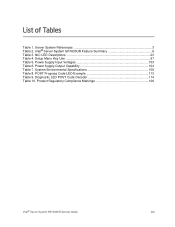
Setup Menu Key Use 97 Table 5. POST Progress Code LED Example 113 Table 9. Server System References 3 Table 2. Power Supply Output Capability 104 Table 7. System Environmental Specifications 105 Table 8. Power Supply Input Voltages 103 Table 6. Product Regulatory Compliance Markings 126 Intel® Server System SR1600UR Service Guide xvii Intel® Server System SR1600UR Feature Summary 6 Table 3. Diagnostic LED POST Code Decoder 114 Table 10. List of Tables Table 1. NIC LED Descriptions 23 Table 4.
Setup Menu Key Use 97 Table 5. POST Progress Code LED Example 113 Table 9. Server System References 3 Table 2. Power Supply Output Capability 104 Table 7. System Environmental Specifications 105 Table 8. Power Supply Input Voltages 103 Table 6. Product Regulatory Compliance Markings 126 Intel® Server System SR1600UR Service Guide xvii Intel® Server System SR1600UR Feature Summary 6 Table 3. Diagnostic LED POST Code Decoder 114 Table 10. List of Tables Table 1. NIC LED Descriptions 23 Table 4.
Service Guide
Page 19
...; Intel® Server System SR1600URHS (hot-swap hard drive system) Unless noted otherwise, all references to the Intel® Server System SR1600UR refer to herein as the "hardware box" Intel® Server System SR1600UR Service Guide 1 Intel® Server System SR1600UR Contents Your Intel® Server System SR1600UR (fixed mount hard drive system) ships with the following items: • Intel® Server Board S5520UR, installed in the server system • One 600-W power supply, installed in the server system...
...; Intel® Server System SR1600URHS (hot-swap hard drive system) Unless noted otherwise, all references to the Intel® Server System SR1600UR refer to herein as the "hardware box" Intel® Server System SR1600UR Service Guide 1 Intel® Server System SR1600UR Contents Your Intel® Server System SR1600UR (fixed mount hard drive system) ships with the following items: • Intel® Server Board S5520UR, installed in the server system • One 600-W power supply, installed in the server system...
Service Guide
Page 20
... Start User's Guide, in the server system product box • Intel® Server Deployment Toolkit 3.0 CD • Intel® System Management Software DVD Intel® Server System SR1600URHS Contents Your Intel® Server System SR1600URHS (hot-swap hard drive system) ships with the following items: • Intel® Server Board S5520UR, installed in the server system • One 600-W power supply, installed in the server system • Full-length and full...
... Start User's Guide, in the server system product box • Intel® Server Deployment Toolkit 3.0 CD • Intel® System Management Software DVD Intel® Server System SR1600URHS Contents Your Intel® Server System SR1600URHS (hot-swap hard drive system) ships with the following items: • Intel® Server Board S5520UR, installed in the server system • One 600-W power supply, installed in the server system • Full-length and full...

Service Guide
Page 26
Table 2. Intel® Server System SR1600UR Feature Summary Feature LEDs and displays Description LEDs with standard control panel: • NIC1 Activity • NIC2 Activity • Power/Sleep • System Status • System Identification • Hard Drive Activity Power Supply Fans System Management Intel® Light-Guided diagnostic LEDs: • Fan Fault • DIMM Fault • CPU Fault • 5V-STBY • System Status...
Table 2. Intel® Server System SR1600UR Feature Summary Feature LEDs and displays Description LEDs with standard control panel: • NIC1 Activity • NIC2 Activity • Power/Sleep • System Status • System Identification • Hard Drive Activity Power Supply Fans System Management Intel® Light-Guided diagnostic LEDs: • Fan Fault • DIMM Fault • CPU Fault • 5V-STBY • System Status...

Service Guide
Page 27
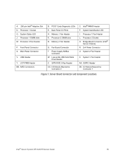
... use the Quick Reference Label provided on the inside of your server system. Power Supply D. Processor air duct H. Control panel (standard control panel shown) K. Front bezel (optional Figure 2. Server System Components Intel® Server System SR1600UR Service Guide 9 Air Baffle C. Rack handles B. swap hard drive system L. If you are near the system, you identify the components of the chassis cover to assist...
... use the Quick Reference Label provided on the inside of your server system. Power Supply D. Processor air duct H. Control panel (standard control panel shown) K. Front bezel (optional Figure 2. Server System Components Intel® Server System SR1600UR Service Guide 9 Air Baffle C. Rack handles B. swap hard drive system L. If you are near the system, you identify the components of the chassis cover to assist...
Service Guide
Page 33
... P. Processor 2 DIMM slots N. Processor 2 Socket O. System 1 Fan Header AA. Power Supply SMBus Connector W. SATA Connectors B. Processor 1 Socket G. USB Header Y. System Identification LED I /O Module Mezzanine Connector 1 Figure 7. I . Fan Board Connector T. LCP IPMB Header BB. Low-profile USB Solid State Drive Header Z. SGPIO Header DD. Server Board Connector and Component Locations Intel® Server System SR1600UR Service Guide 15 POST Code...
... P. Processor 2 DIMM slots N. Processor 2 Socket O. System 1 Fan Header AA. Power Supply SMBus Connector W. SATA Connectors B. Processor 1 Socket G. USB Header Y. System Identification LED I /O Module Mezzanine Connector 1 Figure 7. I . Fan Board Connector T. LCP IPMB Header BB. Low-profile USB Solid State Drive Header Z. SGPIO Header DD. Server Board Connector and Component Locations Intel® Server System SR1600UR Service Guide 15 POST Code...

Service Guide
Page 48
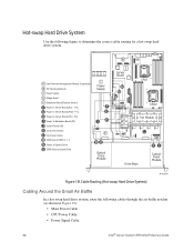
... 30 Intel® Server System SR1600UR Service Guide P2) H Power to Fan Board (P3) I Fan Power Cables J Control Panel USB K Control Panel Data L Power to Fixed HDD 0 M SATA Data to Fixed HDD 0 N Power to Fixed HDD 1 O SATA Data to Fixed HDD 1 P Power to Fixed HDD 2 Q SATA Data to Fixed HDD 2 R SATA Data to Optical Drive LS Power to Optical Drive C Power Supply Server...
... 30 Intel® Server System SR1600UR Service Guide P2) H Power to Fan Board (P3) I Fan Power Cables J Control Panel USB K Control Panel Data L Power to Fixed HDD 0 M SATA Data to Fixed HDD 0 N Power to Fixed HDD 1 O SATA Data to Fixed HDD 1 P Power to Fixed HDD 2 Q SATA Data to Fixed HDD 2 R SATA Data to Optical Drive LS Power to Optical Drive C Power Supply Server...
Service Guide
Page 50
... 19): • Main Power Cable • CPU Power Cable • Power Signal Cable 32 Intel® Server System SR1600UR Service Guide B A A Intel® Remote Management Module 3 (optional) B I Power to Backplane Board (P3) J Control Panel USB K Control Panel Data L Fan Power Cables M SATA Data to HDD 0, 1, 2 N Power to Optical Drive O SATA Data to Server Board (CPU - P1) H Power to Optical Drive C Power Supply F G IH E NO Optical...
... 19): • Main Power Cable • CPU Power Cable • Power Signal Cable 32 Intel® Server System SR1600UR Service Guide B A A Intel® Remote Management Module 3 (optional) B I Power to Backplane Board (P3) J Control Panel USB K Control Panel Data L Fan Power Cables M SATA Data to HDD 0, 1, 2 N Power to Optical Drive O SATA Data to Server Board (CPU - P1) H Power to Optical Drive C Power Supply F G IH E NO Optical...
Service Guide
Page 101
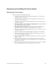
... Small Air Baffle" on page 69. 9. Remove the Intel® RMM3, if installed. Intel® Server System SR1600UR Service Guide 83 If installed, remove the PCI riser assembly. Remove the I /O Expansion Module" on page 56. 4. If installed, remove memory, processor heatsink(s), and processor(s) from the power supply to the server board. 8. For instructions, see "Removing the I /O expansion module...
... Small Air Baffle" on page 69. 9. Remove the Intel® RMM3, if installed. Intel® Server System SR1600UR Service Guide 83 If installed, remove the PCI riser assembly. Remove the I /O Expansion Module" on page 56. 4. If installed, remove memory, processor heatsink(s), and processor(s) from the power supply to the server board. 8. For instructions, see "Removing the I /O expansion module...
Service Guide
Page 103
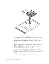
..." on page 48. 5. For instructions, see "Installing the Small Air Baffle" on page 49 6. Install the system fan assembly. Hot-swap hard drive systems with passive backplane only: Connect the hard drive SATA cables from the power supply to the server board. 10. Intel® Server System SR1600UR Service Guide 85 B A AF002914 Figure 75. Install processor(s). Connect all the...
..." on page 48. 5. For instructions, see "Installing the Small Air Baffle" on page 49 6. Install the system fan assembly. Hot-swap hard drive systems with passive backplane only: Connect the hard drive SATA cables from the power supply to the server board. 10. Intel® Server System SR1600UR Service Guide 85 B A AF002914 Figure 75. Install processor(s). Connect all the...

Service Guide
Page 105
... battery according to the RTC. The power supply can be replaced if it in Figure 77). Intel® Server System SR1600UR Service Guide 87 Remove the new lithium battery from the system or wall outlet. Before removing or replacing the power supply, you must first take the server out of service, turn off all power cables. 2. Replacing the Backup Battery 6. Dispose...
... battery according to the RTC. The power supply can be replaced if it in Figure 77). Intel® Server System SR1600UR Service Guide 87 Remove the new lithium battery from the system or wall outlet. Before removing or replacing the power supply, you must first take the server out of service, turn off all power cables. 2. Replacing the Backup Battery 6. Dispose...

Service Guide
Page 106
...). 2. B A B AF000367 Figure 78. Unplug the front panel and USB cables from the Server System 3. Removing Power Supply Module from the backplane (see letter "C" in hot-swap hard drive systems. Caution: The control panel is NOT hot-swappable. Replacing the Control Panel Module (Hot-swap Hard...devices connected to the system, turn off the system by pressing the power button, and unplug the AC power cord from the system or wall outlet. 1. Note: The Intel® Local Control Panel is only supported in Figure 79). 88 Intel® Server System SR1600UR Service Guide Before removing...
...). 2. B A B AF000367 Figure 78. Unplug the front panel and USB cables from the Server System 3. Removing Power Supply Module from the backplane (see letter "C" in hot-swap hard drive systems. Caution: The control panel is NOT hot-swappable. Replacing the Control Panel Module (Hot-swap Hard...devices connected to the system, turn off the system by pressing the power button, and unplug the AC power cord from the system or wall outlet. 1. Note: The Intel® Local Control Panel is only supported in Figure 79). 88 Intel® Server System SR1600UR Service Guide Before removing...

Service Guide
Page 111
... replaced if one of service, turn off the system by pressing the power button, and unplug the AC power cord from the module (see letter "B" in the power supply fails, the power supply must first take the server out of the fans in Figure 84). If one of them fails. Intel® Server System SR1600UR Service Guide 93 A B AF000368 Figure 83. Replacing...
... replaced if one of service, turn off the system by pressing the power button, and unplug the AC power cord from the module (see letter "B" in the power supply fails, the power supply must first take the server out of the fans in Figure 84). If one of them fails. Intel® Server System SR1600UR Service Guide 93 A B AF000368 Figure 83. Replacing...

Service Guide
Page 121
... used for determining agency input current markings. Intel® Server System SR1600UR Service Guide 103 Table 5. This is measured at 100 VAC and 200 VAC. Maximum input current at high input voltage range is measured at 90 VAC, at maximum load. Power Supply Input Voltages Parameter Voltage (110) Voltage (...input current at low input voltage range is measured at 180 VAC, at maximum load. Appendix A: Technical Reference 600-W Single Power Supply Input Voltages The power supply must operate within all specified limits over the input voltage range shown in the following table.
... used for determining agency input current markings. Intel® Server System SR1600UR Service Guide 103 Table 5. This is measured at 100 VAC and 200 VAC. Maximum input current at high input voltage range is measured at 90 VAC, at maximum load. Power Supply Input Voltages Parameter Voltage (110) Voltage (...input current at low input voltage range is measured at 180 VAC, at maximum load. Appendix A: Technical Reference 600-W Single Power Supply Input Voltages The power supply must operate within all specified limits over the input voltage range shown in the following table.

Service Guide
Page 122
... exceed the combined total wattage of 90 Watts for each voltage. Exceeding a combined 90 Watts will overload the power subsystem and may cause the power supplies to overheat and malfunction. 104 Intel® Server System SR1600UR Service Guide Table 6. Power Supply Output Capability Voltage +3.3 V +5.0 V +12.0 V1 +12.0 V2 -12.0 V3 +12.0 V4 -12.0 V 5.0 VSB Minimum OCP Limits Maximum OCP...
... exceed the combined total wattage of 90 Watts for each voltage. Exceeding a combined 90 Watts will overload the power subsystem and may cause the power supplies to overheat and malfunction. 104 Intel® Server System SR1600UR Service Guide Table 6. Power Supply Output Capability Voltage +3.3 V +5.0 V +12.0 V1 +12.0 V2 -12.0 V3 +12.0 V4 -12.0 V 5.0 VSB Minimum OCP Limits Maximum OCP...

Service Guide
Page 141
...ensure EMC compliance with your local regional rules and regulations, before computer integration, make sure that the server system, power supply, and other regulatory approvals of it into a Class B system does not result in a Class B device. Product Safety Compliance • UL60950 - The final ... guide to include all country national deviations) • GS Certification (Germany) Intel® Server System SR1600UR Service Guide 123 Use only the described, regulated components specified in this server board. This is sold. Use of other products/components will most likely result...
...ensure EMC compliance with your local regional rules and regulations, before computer integration, make sure that the server system, power supply, and other regulatory approvals of it into a Class B system does not result in a Class B device. Product Safety Compliance • UL60950 - The final ... guide to include all country national deviations) • GS Certification (Germany) Intel® Server System SR1600UR Service Guide 123 Use only the described, regulated components specified in this server board. This is sold. Use of other products/components will most likely result...

Service Guide
Page 147
... bevor Instandhaltung. "WARNING:" "Apparaten skall anslutas till jordat uttag, när den ansluts till ett nätverk." Stand-by power Intel® Server System SR1600UR Service Guide 129 To reduce the risk of electrical shock, disconnect (2) two power supply cords before servicing. "Laite on liitettävä suojamaadoituskoskettimilla varustettuun pistorasiaan." Product Regulatory Compliance Markings Regulatory Compliance Safety Country...
... bevor Instandhaltung. "WARNING:" "Apparaten skall anslutas till jordat uttag, när den ansluts till ett nätverk." Stand-by power Intel® Server System SR1600UR Service Guide 129 To reduce the risk of electrical shock, disconnect (2) two power supply cords before servicing. "Laite on liitettävä suojamaadoituskoskettimilla varustettuun pistorasiaan." Product Regulatory Compliance Markings Regulatory Compliance Safety Country...
