Service Guide
Page 3
... information, feature information, and step by step instructions on the Intel® Server System SR1600UR, and the location where they can be required to add and replace components on adding and replacing components. The back of this manual, see http://www.intel.com/p/en_US/support/highlights/server/s5520ur. For the latest version of this manual provides technical...
... information, feature information, and step by step instructions on the Intel® Server System SR1600UR, and the location where they can be required to add and replace components on adding and replacing components. The back of this manual, see http://www.intel.com/p/en_US/support/highlights/server/s5520ur. For the latest version of this manual provides technical...

Service Guide
Page 5
... sämtliche Warn- Intel® Server System SR1600UR Service Guide v Vea Intel Server Boards and Server Chassis Safety Information en el Intel® Server Deployment Toolkit 3.0 CD y/o en http://www.intel.com/support/motherboards/server/sb/cs-010770.htm. und Sicherheitshinweise in this document before performing any of the instructions. Consultez Intel Server Boards and Server Chassis Safety Information sur le Intel® Server Deployment Toolkit 3.0 CD...
... sämtliche Warn- Intel® Server System SR1600UR Service Guide v Vea Intel Server Boards and Server Chassis Safety Information en el Intel® Server Deployment Toolkit 3.0 CD y/o en http://www.intel.com/support/motherboards/server/sb/cs-010770.htm. und Sicherheitshinweise in this document before performing any of the instructions. Consultez Intel Server Boards and Server Chassis Safety Information sur le Intel® Server Deployment Toolkit 3.0 CD...

Service Guide
Page 9
... of Server System ...22 Back Panel Connectors 23 SAS/SATA Backplanes ...24 Active Backplane ...24 Passive Backplane ...25 RAID Support ...26 Advanced Management Options 26 Intel® Remote Management Module 3 26 Rack Mount Options ...27 Chapter 3: Hardware Installations and Upgrades 29 Before You Begin ...29 Tools and Supplies Needed 29 System References ...29 Intel® Server System SR1600UR Service...
... of Server System ...22 Back Panel Connectors 23 SAS/SATA Backplanes ...24 Active Backplane ...24 Passive Backplane ...25 RAID Support ...26 Advanced Management Options 26 Intel® Remote Management Module 3 26 Rack Mount Options ...27 Chapter 3: Hardware Installations and Upgrades 29 Before You Begin ...29 Tools and Supplies Needed 29 System References ...29 Intel® Server System SR1600UR Service...
Service Guide
Page 15
... 45 Figure 31. Installing the Memory 48 Figure 35. Removing the Processor Protective Cover 51 Figure 39. Intel® Server System SR1600UR 5 Figure 2. Cabling Around the Small Air Baffle (Hot-swap Hard Drive System 33 Figure 20. Front View with Bezel supporting the Intel® Local Control Panel 37 Figure 22. Installing PCI Riser Assembly into the...
... 45 Figure 31. Installing the Memory 48 Figure 35. Removing the Processor Protective Cover 51 Figure 39. Intel® Server System SR1600UR 5 Figure 2. Cabling Around the Small Air Baffle (Hot-swap Hard Drive System 33 Figure 20. Front View with Bezel supporting the Intel® Local Control Panel 37 Figure 22. Installing PCI Riser Assembly into the...

Service Guide
Page 21
... to assemble your system and install components Intel® Server System SR1600UR Technical Product Specification Available at: http://www.intel.com/p/en_US/support/highlights/server/s5520ur Intel® Server Board S5520UR Technical Product Specification Available at: http://www.intel.com/p/en_US/support/highlights/server/s5520ur Intel® Server Board S5520UR Technical Product Specification Available at: http://www.intel.com/p/en_US/support/highlights/server/s5520ur Intel® Server System SR1600UR Quick Start User...
... to assemble your system and install components Intel® Server System SR1600UR Technical Product Specification Available at: http://www.intel.com/p/en_US/support/highlights/server/s5520ur Intel® Server Board S5520UR Technical Product Specification Available at: http://www.intel.com/p/en_US/support/highlights/server/s5520ur Intel® Server Board S5520UR Technical Product Specification Available at: http://www.intel.com/p/en_US/support/highlights/server/s5520ur Intel® Server System SR1600UR Quick Start User...
Service Guide
Page 22
... : http://www.intel.com/go/servermanagement/ 4 Intel® Server System SR1600UR Service Guide Table 1. To make sure your system falls within the allowed power budget For software to manage your Intel® server Power Budget Analysis Tool Available at: http://www.intel.com/p/en_US/support/highlights/server/s5520ur Intel® System Management Software Available at : http://www.intel.com/p/en_US/support/highlights/server/s5520ur Click the...
... : http://www.intel.com/go/servermanagement/ 4 Intel® Server System SR1600UR Service Guide Table 1. To make sure your system falls within the allowed power budget For software to manage your Intel® server Power Budget Analysis Tool Available at: http://www.intel.com/p/en_US/support/highlights/server/s5520ur Intel® System Management Software Available at : http://www.intel.com/p/en_US/support/highlights/server/s5520ur Click the...

Service Guide
Page 24
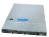
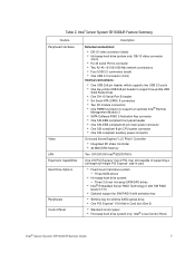
Table 2. max chassis weight Intel® Server Board S5520UR Support for 800/1066/1333 MT/s ECC registered (RDIMM) or unbuffered (UDIMM) DDR3 memory • Intel® 5520 Chipset I/O Hub • Intel® 82801Jx I/O Controller Hub 6 Intel® Server System SR1600UR Service Guide Intel® Server System SR1600UR Feature Summary Feature Dimensions Server Board Processor Memory Chipset Description • 1.703 inches (43.3 mm) high • 16...
Table 2. max chassis weight Intel® Server Board S5520UR Support for 800/1066/1333 MT/s ECC registered (RDIMM) or unbuffered (UDIMM) DDR3 memory • Intel® 5520 Chipset I/O Hub • Intel® 82801Jx I/O Controller Hub 6 Intel® Server System SR1600UR Service Guide Intel® Server System SR1600UR Feature Summary Feature Dimensions Server Board Processor Memory Chipset Description • 1.703 inches (43.3 mm) high • 16...
Service Guide
Page 25
... • 32 MB DDR2 Memory Two 10/100/1000 Intel® 82575 PHYs One x16 PCI Express* Gen 2 PCI riser slot capable of supporting a full-length full-height PCI Express* add-in Card slot (Gen 2) • Standard control panel • Hot-swap hard drive system only: Intel® Local Control Panel Intel® Server System SR1600UR Service Guide 7 Three...
... • 32 MB DDR2 Memory Two 10/100/1000 Intel® 82575 PHYs One x16 PCI Express* Gen 2 PCI riser slot capable of supporting a full-length full-height PCI Express* add-in Card slot (Gen 2) • Standard control panel • Hot-swap hard drive system only: Intel® Local Control Panel Intel® Server System SR1600UR Service Guide 7 Three...

Service Guide
Page 26
... supply • Five 40x40x56-mm, non-redundant, variable-speed, dual-rotor system fans • Two non-redundant 40-mm power supply fans On-board ServerEngines* LLC Pilot II Controller • Integrated Baseboard Management Controller (Integrated BMC), IPMI 2.0 compliant • Integrated Super I/O on LPC interface Support for Intel® System Management Software 8 Intel® Server System SR1600UR Service Guide
... supply • Five 40x40x56-mm, non-redundant, variable-speed, dual-rotor system fans • Two non-redundant 40-mm power supply fans On-board ServerEngines* LLC Pilot II Controller • Integrated Baseboard Management Controller (Integrated BMC), IPMI 2.0 compliant • Integrated Super I/O on LPC interface Support for Intel® System Management Software 8 Intel® Server System SR1600UR Service Guide

Service Guide
Page 27
...; Three fixed hard drives supported in fixed mount hard drive system • Three hot-swap drives supported in hot-swap hard drive system J. Server Board E. Control panel (standard control panel shown) K. C DEF B G A M L K H I . Fan Board used in fixed mount hard drive system / Backpane used in hot- PCI add-in identifying components. Server System Components Intel® Server System SR1600UR Service Guide 9 PCI card...
...; Three fixed hard drives supported in fixed mount hard drive system • Three hot-swap drives supported in hot-swap hard drive system J. Server Board E. Control panel (standard control panel shown) K. C DEF B G A M L K H I . Fan Board used in fixed mount hard drive system / Backpane used in hot- PCI add-in identifying components. Server System Components Intel® Server System SR1600UR Service Guide 9 PCI card...

Service Guide
Page 36
...; Slimline DVD-RW Drive: AXXSATADVDRWROM Note: The Intel® Server System SR1600UR does not support all SAS or Serial ATA (SATA) hard drives. For a web link to install an optional SATA optical drive. Intel provides accessory kits for these drives. 18 Intel® Server System SR1600UR Service Guide For instructions on the Intel® Server System SR1600UR (Product Code: SR1600URHS) only. For a web link...
...; Slimline DVD-RW Drive: AXXSATADVDRWROM Note: The Intel® Server System SR1600UR does not support all SAS or Serial ATA (SATA) hard drives. For a web link to install an optional SATA optical drive. Intel provides accessory kits for these drives. 18 Intel® Server System SR1600UR Service Guide For instructions on the Intel® Server System SR1600UR (Product Code: SR1600URHS) only. For a web link...

Service Guide
Page 37
... indicates network activity. Powers on page 88. C. E. B. D. No light indicates the power is off the system. Continuous green light indicates the system has power applied to which it or the system is in ACPI S4 or S5 state. Control Panel The Intel® Server System SR1600UR supports the following types of control panels: • Standard Control Panel •...
... indicates network activity. Powers on page 88. C. E. B. D. No light indicates the power is off the system. Continuous green light indicates the system has power applied to which it or the system is in ACPI S4 or S5 state. Control Panel The Intel® Server System SR1600UR supports the following types of control panels: • Standard Control Panel •...

Service Guide
Page 38
...indicates degraded performance. I H G TP02099 20 Intel® Server System SR1600UR Service Guide J. Allows you to attach a video monitor to issue a non-maskable interrupt. Blinking amber indicates a non-critical condition. Turns on the hot-swap hard drive system (Product Code: SR1600URHS). NOTE: The video port... option is not activated. G. K. Puts the server in the hot-swap hard drive system (Product Code: SR1600URHS). Note: The Intel® Local Control Panel is only supported in a halt-...
...indicates degraded performance. I H G TP02099 20 Intel® Server System SR1600UR Service Guide J. Allows you to attach a video monitor to issue a non-maskable interrupt. Blinking amber indicates a non-critical condition. Turns on the hot-swap hard drive system (Product Code: SR1600URHS). NOTE: The video port... option is not activated. G. K. Puts the server in the hot-swap hard drive system (Product Code: SR1600URHS). Note: The Intel® Local Control Panel is only supported in a halt-...
Service Guide
Page 42
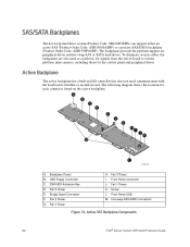
... I. Front Panel Connector J. The backplanes provide the platform support for each connector found on the active backplane. A B C D E F G HI J K M L TP02172 A. SW RAID Activation Key D. Hot-swap SAS/SATA Connectors Figure 14. Backplane Power B. Bridge Board Connector F. Fan 3 Power H. Active SAS Backplane Components 24 Intel® Server System SR1600UR Service Guide Fan 1 Power K. USB Floppy Connector C. To...
... I. Front Panel Connector J. The backplanes provide the platform support for each connector found on the active backplane. A B C D E F G HI J K M L TP02172 A. SW RAID Activation Key D. Hot-swap SAS/SATA Connectors Figure 14. Backplane Power B. Bridge Board Connector F. Fan 3 Power H. Active SAS Backplane Components 24 Intel® Server System SR1600UR Service Guide Fan 1 Power K. USB Floppy Connector C. To...

Service Guide
Page 44
... Onboard SATA Controller option is included on page 70. 26 Intel® Server System SR1600UR Service Guide For information on configuring RAID, see "Installing and Removing the Intel® Remote Management Module 3" on the Intel® Server Deployment Toolkit 3.0 CD. Advanced Management Options Intel® Remote Management Module 3 The Intel® Remote Management Module 3 plugs into a dedicated connector on...
... Onboard SATA Controller option is included on page 70. 26 Intel® Server System SR1600UR Service Guide For information on configuring RAID, see "Installing and Removing the Intel® Remote Management Module 3" on the Intel® Server Deployment Toolkit 3.0 CD. Advanced Management Options Intel® Remote Management Module 3 The Intel® Remote Management Module 3 plugs into a dedicated connector on...

Service Guide
Page 54
...Product Order Code: ADWBEZBLACK) • Bezel for use with . Disconnect the power cable(s) and proceed with Bezel supporting the Standard Control Panel 36 Intel® Server System SR1600UR Service Guide The following figures. TP02197 Figure 20. Depress the two safety locks (one on your bezel, see... completed, re-connect the power cable(s). 4. If you position it as optional accessories for the Intel® Server System SR1600UR. Engage the matching rails and slide the server chassis into the rack until the two safety stops lock into the rack so that the cables do...
...Product Order Code: ADWBEZBLACK) • Bezel for use with . Disconnect the power cable(s) and proceed with Bezel supporting the Standard Control Panel 36 Intel® Server System SR1600UR Service Guide The following figures. TP02197 Figure 20. Depress the two safety locks (one on your bezel, see... completed, re-connect the power cable(s). 4. If you position it as optional accessories for the Intel® Server System SR1600UR. Engage the matching rails and slide the server chassis into the rack until the two safety stops lock into the rack so that the cables do...

Service Guide
Page 55
At each end of the server system until it clicks into place. Front View with the center guide on page 94. Push the bezel onto the front of the bezel, line up the center notch on the bezel with Bezel supporting the Intel® Local Control Panel Installing ...the Front Bezel Before installing the bezel, you must install the rack handles. To install the front bezel, follow these steps: 1. Installing the Front Bezel AF002770 Intel® Server System SR1600UR Service Guide 37 TP02198 Figure 21...
At each end of the server system until it clicks into place. Front View with the center guide on page 94. Push the bezel onto the front of the bezel, line up the center notch on the bezel with Bezel supporting the Intel® Local Control Panel Installing ...the Front Bezel Before installing the bezel, you must install the rack handles. To install the front bezel, follow these steps: 1. Installing the Front Bezel AF002770 Intel® Server System SR1600UR Service Guide 37 TP02198 Figure 21...

Service Guide
Page 70
... you do not damage the TIM. A B AF002840 Figure 40. Pay close attention to the steps and perform each step exactly as indicated to support processor cooling. 52 Intel® Server System SR1600UR Service Guide Note: New unused heatsinks have adequate TIM on the bottom of it. Install the heatsink. Caution: Improper installation can damage the...
... you do not damage the TIM. A B AF002840 Figure 40. Pay close attention to the steps and perform each step exactly as indicated to support processor cooling. 52 Intel® Server System SR1600UR Service Guide Note: New unused heatsinks have adequate TIM on the bottom of it. Install the heatsink. Caution: Improper installation can damage the...

Service Guide
Page 75
...end of supported hardware, see "Additional Information and Software" on page 30. Note: For a web link to the system, turn off the system by accessing the drive carrier latch from the system or wall outlet. Before removing or replacing the drive, you must first take the server out ...connected to a list of the black drive rail (see "Cable Routing" on page 3. Intel® Server System SR1600UR Service Guide 57 Installing and Removing a Fixed Mount Hard Drive (Fixed Mount Hard Drive System Only) Caution: Fixed mount hard drives are NOT hot-swappable. Installing the Small Air Baffle...
...end of supported hardware, see "Additional Information and Software" on page 30. Note: For a web link to the system, turn off the system by accessing the drive carrier latch from the system or wall outlet. Before removing or replacing the drive, you must first take the server out ...connected to a list of the black drive rail (see "Cable Routing" on page 3. Intel® Server System SR1600UR Service Guide 57 Installing and Removing a Fixed Mount Hard Drive (Fixed Mount Hard Drive System Only) Caution: Fixed mount hard drives are NOT hot-swappable. Installing the Small Air Baffle...

Service Guide
Page 79
... SATA drives in Figure 50). 2. For a web link to the drive carrier (see letter "A" in the Intel® Server System SR1600UR (Product Code: SR1600URHS). Remove the plastic retention device (see "Additional Information and Software" on the lever to maintain proper...attach the plastic retention device or the previously installed hard drive to a list of supported hard drives, see letter "B" in Figure 51). Intel® Server System SR1600UR Service Guide 61 Note: The server system does not support all hard drives. Cautions: If you install less than three drives or devices,...
... SATA drives in Figure 50). 2. For a web link to the drive carrier (see letter "A" in the Intel® Server System SR1600UR (Product Code: SR1600URHS). Remove the plastic retention device (see "Additional Information and Software" on the lever to maintain proper...attach the plastic retention device or the previously installed hard drive to a list of supported hard drives, see letter "B" in Figure 51). Intel® Server System SR1600UR Service Guide 61 Note: The server system does not support all hard drives. Cautions: If you install less than three drives or devices,...