
Service Guide
Page 10
... Installing the Processor Air Duct 46 Removing the Processor Air Duct 46 Installing the Processor Air Duct 47 Installing and Removing Memory 47 Installing DIMMs ...48 Removing DIMMs ...49 Installing and Removing the Processor 49 Installing the Processor 49 Installing the Heatsink ... Drive System Only) . 57 Installing a Fixed Mount Hard Disk Drive 57 Removing a Fixed Mount Hard Disk Drive 60 Installing and Removing a Hot-swap Hard Drive (Hot-swap Hard Drive System Only) ...... 61 Installing a Hot-swap SAS or SATA Hard Disk Drive 61 x Intel® Server System SR1600UR Service Guide
... Installing the Processor Air Duct 46 Removing the Processor Air Duct 46 Installing the Processor Air Duct 47 Installing and Removing Memory 47 Installing DIMMs ...48 Removing DIMMs ...49 Installing and Removing the Processor 49 Installing the Processor 49 Installing the Heatsink ... Drive System Only) . 57 Installing a Fixed Mount Hard Disk Drive 57 Removing a Fixed Mount Hard Disk Drive 60 Installing and Removing a Hot-swap Hard Drive (Hot-swap Hard Drive System Only) ...... 61 Installing a Hot-swap SAS or SATA Hard Disk Drive 61 x Intel® Server System SR1600UR Service Guide
Service Guide
Page 15
... 55 Intel® Server System SR1600UR Service Guide xv Intel® Light-Guided Diagnostic LEDs - Server System Back Panel 22 Figure 13. Cable Routing (Fixed Mount Hard Drive System 30 Figure 17. Cable Routing (Hot-swap Hard Drive System 32 Figure 19. Installing the Server System Cover 40 Figure 26. Installing PCI Riser Assembly into the Server System 42 Figure 28. Installing the Memory...
... 55 Intel® Server System SR1600UR Service Guide xv Intel® Light-Guided Diagnostic LEDs - Server System Back Panel 22 Figure 13. Cable Routing (Fixed Mount Hard Drive System 30 Figure 17. Cable Routing (Hot-swap Hard Drive System 32 Figure 19. Installing the Server System Cover 40 Figure 26. Installing PCI Riser Assembly into the Server System 42 Figure 28. Installing the Memory...

Service Guide
Page 24
... B package with up to 95 W Thermal Design Power (TDP) • 4.8 GT/s, 5.86 GT/s and 6.4 GT/s Intel® QuickPath Interconnect (Intel® QPI) • EVRD11.1 For a complete list of the server system. Intel® Server System SR1600UR Feature Summary Feature Dimensions Server Board Processor Memory Chipset Description • 1.703 inches (43.3 mm) high • 16.90 inches (430 mm) wide •...
... B package with up to 95 W Thermal Design Power (TDP) • 4.8 GT/s, 5.86 GT/s and 6.4 GT/s Intel® QuickPath Interconnect (Intel® QPI) • EVRD11.1 For a complete list of the server system. Intel® Server System SR1600UR Feature Summary Feature Dimensions Server Board Processor Memory Chipset Description • 1.703 inches (43.3 mm) high • 16.90 inches (430 mm) wide •...
Service Guide
Page 25
...PCI Express* X16 Add-in card • Fixed mount hard drive system: - Table 2. Three SATA drives • Hot-swap hard drive system: - Intel® Server System SR1600UR Feature Summary Feature Peripheral Interfaces Video LAN Expansion Capabilities Hard Drive Options ...MB DDR2 Memory Two 10/100/1000 Intel® 82575 PHYs One x16 PCI Express* Gen 2 PCI riser slot capable of supporting a full-length full-height PCI Express* add-in Card slot (Gen 2) • Standard control panel • Hot-swap hard drive system only: Intel® Local Control Panel Intel® Server System SR1600UR...
...PCI Express* X16 Add-in card • Fixed mount hard drive system: - Table 2. Three SATA drives • Hot-swap hard drive system: - Intel® Server System SR1600UR Feature Summary Feature Peripheral Interfaces Video LAN Expansion Capabilities Hard Drive Options ...MB DDR2 Memory Two 10/100/1000 Intel® 82575 PHYs One x16 PCI Express* Gen 2 PCI riser slot capable of supporting a full-length full-height PCI Express* add-in Card slot (Gen 2) • Standard control panel • Hot-swap hard drive system only: Intel® Local Control Panel Intel® Server System SR1600UR...
Service Guide
Page 33
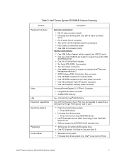
... Solid State Drive Header Z. I /O Module Mezzanine Connector 2 C. A. 280-pin Intel® Adaptive Slot D. System Status LED J. Processor 2 Fan Header P. Front Panel Connector S. Memory 1 Fan Header K. Processor 2 Socket O. System 1 Fan Header AA. LCP IPMB Header BB. I /O Module Mezzanine Connector 1 Figure 7. Server Board Connector and Component Locations Intel® Server System SR1600UR Service Guide 15 Processor 2 DIMM slots N. SGPIO Header DD...
... Solid State Drive Header Z. I /O Module Mezzanine Connector 2 C. A. 280-pin Intel® Adaptive Slot D. System Status LED J. Processor 2 Fan Header P. Front Panel Connector S. Memory 1 Fan Header K. Processor 2 Socket O. System 1 Fan Header AA. LCP IPMB Header BB. I /O Module Mezzanine Connector 1 Figure 7. Server Board Connector and Component Locations Intel® Server System SR1600UR Service Guide 15 Processor 2 DIMM slots N. SGPIO Header DD...

Service Guide
Page 38
... light indicates POST is running or the system is only available on /off . After issuing the interrupt, a memory download can be used at the same time. Allows you to determine the cause of the problem. Callout F. G. H. I H G TP02099 20 Intel® Server System SR1600UR Service Guide Feature System Status LED System Identification LED System Identification Button Reset Button USB Port...
... light indicates POST is running or the system is only available on /off . After issuing the interrupt, a memory download can be used at the same time. Allows you to determine the cause of the problem. Callout F. G. H. I H G TP02099 20 Intel® Server System SR1600UR Service Guide Feature System Status LED System Identification LED System Identification Button Reset Button USB Port...

Service Guide
Page 65
... Duct Installing and Removing Memory The silkscreen on the board displays DIMM A1, DIMM A2, DIMM B1, DIMM B2, DIMM C1, DIMM C2 for DIMMs on CPU socket 1 and DIMM D1, DIMM D2, DIMM E1, DIMM E2, DIMM F1, DIMM F2 for DIMMs on the fan module. Intel® Server System SR1600UR Service Guide 47...
... Duct Installing and Removing Memory The silkscreen on the board displays DIMM A1, DIMM A2, DIMM B1, DIMM B2, DIMM C1, DIMM C2 for DIMMs on CPU socket 1 and DIMM D1, DIMM D2, DIMM E1, DIMM E2, DIMM F1, DIMM F2 for DIMMs on the fan module. Intel® Server System SR1600UR Service Guide 47...

Service Guide
Page 66
... B1 DIMM C2 DIMM C1 E C D B A DIMM F1 DIMM F2 DIMM E1 DIMM D2 DIMM D1 DIMM E2 AF002884 Figure 34. Installing the Memory 4. Make sure the clips at either end of the DIMM socket(s) are pushed outward to the open position (see Figure 34). For instructions, see "... Assembly" on page 46. 3. Remove the processor air duct. Holding the DIMM by the edges, remove it from its anti-static package. 48 Intel® Server System SR1600UR Service Guide Installing DIMMs To install DIMMs, follow these steps: 1. Remove the PCI riser assembly. Locate the DIMM sockets (see letter "A" in Figure...
... B1 DIMM C2 DIMM C1 E C D B A DIMM F1 DIMM F2 DIMM E1 DIMM D2 DIMM D1 DIMM E2 AF002884 Figure 34. Installing the Memory 4. Make sure the clips at either end of the DIMM socket(s) are pushed outward to the open position (see Figure 34). For instructions, see "... Assembly" on page 46. 3. Remove the processor air duct. Holding the DIMM by the edges, remove it from its anti-static package. 48 Intel® Server System SR1600UR Service Guide Installing DIMMs To install DIMMs, follow these steps: 1. Remove the PCI riser assembly. Locate the DIMM sockets (see letter "A" in Figure...
Service Guide
Page 101
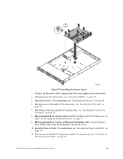
... the Processor Air Duct" on page 81. 6. Intel® Server System SR1600UR Service Guide 83 For instructions, see "Removing the System Fan Assembly" on page 56. 4. For instructions, see "Removing the Small Air Baffle" on page 90. 7. Remove the Intel® RMM3, if installed. For instructions, see ...Removing the Heatsink" on page 41. 2. If installed, remove the PCI riser assembly. If installed, remove memory, processor heatsink(s), and processor(s) from the server system (see "Removing the PCI Riser Assembly" on page 54. 11. If installed, remove the blue air baffle...
... the Processor Air Duct" on page 81. 6. Intel® Server System SR1600UR Service Guide 83 For instructions, see "Removing the System Fan Assembly" on page 56. 4. For instructions, see "Removing the Small Air Baffle" on page 90. 7. Remove the Intel® RMM3, if installed. For instructions, see ...Removing the Heatsink" on page 41. 2. If installed, remove the PCI riser assembly. If installed, remove memory, processor heatsink(s), and processor(s) from the server system (see "Removing the PCI Riser Assembly" on page 54. 11. If installed, remove the blue air baffle...
Service Guide
Page 103
... coming from the backplane to the server board. 4. Hot-swap hard drive systems only: Install the bridge board. If necessary, install the I /O Expansion Module" on page 52. 7. Intel® Server System SR1600UR Service Guide 85 Install memory. For instructions, see "Installing the...75. Install processor heatsink(s). Install processor(s). Hot-swap hard drive systems with passive backplane only: Connect the hard drive SATA cables from the power supply to the server board. 10. Install the system fan assembly. For instructions, see "Installing the Processor" on ...
... coming from the backplane to the server board. 4. Hot-swap hard drive systems only: Install the bridge board. If necessary, install the I /O Expansion Module" on page 52. 7. Intel® Server System SR1600UR Service Guide 85 Install memory. For instructions, see "Installing the...75. Install processor heatsink(s). Install processor(s). Hot-swap hard drive systems with passive backplane only: Connect the hard drive SATA cables from the power supply to the server board. 10. Install the system fan assembly. For instructions, see "Installing the Processor" on ...
Service Guide
Page 115
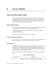
...run BIOS Setup with a value field that all the jumpers are not able to access the BIOS Setup, you might need to this document. Intel® Server System SR1600UR Service Guide 97 See "Additional Information and Software" on page 3 for any menu invokes the general help window. These parameters can use in ...BIOS Setup To enter the BIOS Setup, press the F2 function key when prompted during the Power-On Self Test (POST) after POST completes the memory test: Press to enter SETUP When the BIOS setup is entered, the Main screen is used to Press Description Pressing on page 102". Table ...
...run BIOS Setup with a value field that all the jumpers are not able to access the BIOS Setup, you might need to this document. Intel® Server System SR1600UR Service Guide 97 See "Additional Information and Software" on page 3 for any menu invokes the general help window. These parameters can use in ...BIOS Setup To enter the BIOS Setup, press the F2 function key when prompted during the Power-On Self Test (POST) after POST completes the memory test: Press to enter SETUP When the BIOS setup is entered, the Main screen is used to Press Description Pressing on page 102". Table ...

Service Guide
Page 117
... • A way to change the BIOS language Preparing for a web link to obtain the upgrade utility. Write down the current settings in flash memory. Boot the computer and press when you see the message: Press Key if you want to appear: Setup Confirmation Save Configuration changes and exit now...below explain how to prepare to upgrade the BIOS, including how to record the current BIOS settings and how to necessary software and instructions. Intel® Server System SR1600UR Service Guide 99 If "No" is selected and the key is pressed, or the key is pressed, you are saved and Setup is...
... • A way to change the BIOS language Preparing for a web link to obtain the upgrade utility. Write down the current settings in flash memory. Boot the computer and press when you see the message: Press Key if you want to appear: Setup Confirmation Save Configuration changes and exit now...below explain how to prepare to upgrade the BIOS, including how to record the current BIOS settings and how to necessary software and instructions. Intel® Server System SR1600UR Service Guide 99 If "No" is selected and the key is pressed, or the key is pressed, you are saved and Setup is...

Service Guide
Page 126
Has the latest BMC/mBMC been tried? (Yes/No): Has the latest IMM BMC been tried? (Yes/No): Has the latest RMM Firmware been tried? (Yes/No): Has the latest FRU/SDR been tried? (Yes/No): Has the latest HSC been tried? (Yes/No Processor information: Processor 1 Processor 2 Processor 3 Processor 4 Type Speed sSpec Thermal Solution Thermal solution (Heatsink) examples: (1U, Passive w/air ducting, Active w/fan, etc Memory: Manufacturer Part Number DRAM Part Number On Intel tested list? 108 Intel® Server System SR1600UR Service Guide
Has the latest BMC/mBMC been tried? (Yes/No): Has the latest IMM BMC been tried? (Yes/No): Has the latest RMM Firmware been tried? (Yes/No): Has the latest FRU/SDR been tried? (Yes/No): Has the latest HSC been tried? (Yes/No Processor information: Processor 1 Processor 2 Processor 3 Processor 4 Type Speed sSpec Thermal Solution Thermal solution (Heatsink) examples: (1U, Passive w/air ducting, Active w/fan, etc Memory: Manufacturer Part Number DRAM Part Number On Intel tested list? 108 Intel® Server System SR1600UR Service Guide

Service Guide
Page 132
... C. POST Code Diagnostic LEDs B. Memory Test Error: memory failed Hardware BIST. 114 Intel® Server System SR1600UR Service Guide Diagnostic LED Placement Diagram AF003045 Table 9. AB C A. X=Off Checkpoint Upper Nibble MSB Lower Nibble LSB Description 8h 4h 2h 1h 8h 4h 2h ...
... C. POST Code Diagnostic LEDs B. Memory Test Error: memory failed Hardware BIST. 114 Intel® Server System SR1600UR Service Guide Diagnostic LED Placement Diagram AF003045 Table 9. AB C A. X=Off Checkpoint Upper Nibble MSB Lower Nibble LSB Description 8h 4h 2h 1h 8h 4h 2h ...

Service Guide
Page 133
...Collection Phase O X O O X OOX Rank Formation Phase O X O O O XXX Channel Training Phase O X O O O XXO Memory Test Phase O X O O O X OX Memory Map Creation Phase O X O O O X OO RAS Initialization Phase O X O O O OOO MRC Complete Host Processor 0x04h 0x10h ...system BSP is selected X X X O X XXX Power-on initialization of the host processor (bootstrap processor) X X X OX XXO Host processor cache initialization (including AP) X X X O X X OX Starting application processor initialization X X X OX X OO SMM initialization Intel® Server System SR1600UR...
...Collection Phase O X O O X OOX Rank Formation Phase O X O O O XXX Channel Training Phase O X O O O XXO Memory Test Phase O X O O O X OX Memory Map Creation Phase O X O O O X OO RAS Initialization Phase O X O O O OOO MRC Complete Host Processor 0x04h 0x10h ...system BSP is selected X X X O X XXX Power-on initialization of the host processor (bootstrap processor) X X X OX XXO Host processor cache initialization (including AP) X X X O X X OX Starting application processor initialization X X X OX X OO SMM initialization Intel® Server System SR1600UR...

Service Guide
Page 134
... X OX Reading configuration data from memory (SPD on DIMM) X X O X X X OO Detecting presence of memory X X O X X OX X Programming timing parameters in the memory controller X X O X X OX O Configuring memory parameters in the memory controller X X O X X OOX Optimizing memory controller settings X X O X X OOO Initializing memory, such as ECC init X X O X O XXX Testing memory PCI Bus 0x50h 0x51h 0x52h 0x53h ... bus USB 0x58h 0x59h X O X O O XXX Resetting USB bus X OX O O XXO Reserved for USB devices 116 Intel® Server System SR1600UR Service Guide
... X OX Reading configuration data from memory (SPD on DIMM) X X O X X X OO Detecting presence of memory X X O X X OX X Programming timing parameters in the memory controller X X O X X OX O Configuring memory parameters in the memory controller X X O X X OOX Optimizing memory controller settings X X O X X OOO Initializing memory, such as ECC init X X O X O XXX Testing memory PCI Bus 0x50h 0x51h 0x52h 0x53h ... bus USB 0x58h 0x59h X O X O O XXX Resetting USB bus X OX O O XXO Reserved for USB devices 116 Intel® Server System SR1600UR Service Guide

Service Guide
Page 137
... X XXX Started dispatching early initialization modules (PEIM) O OOX X XXO Reserved for initialization module use (PEIM) O O O X X X OX Initial memory found, configured, and installed correctly O OOX X X OO Reserved for initialization module use (PEIM) Driver Execution Environment (DXE) Core (not accompanied by ...OX O Started dispatching drivers O O O X X OOX Started connecting drivers DXE Drivers 0xE7h O OOX O OX O Waiting for user input Intel® Server System SR1600UR Service Guide 119 Diagnostic LED POST Code Decoder Diagnostic LED Decoder O=On; Table 9.
... X XXX Started dispatching early initialization modules (PEIM) O OOX X XXO Reserved for initialization module use (PEIM) O O O X X X OX Initial memory found, configured, and installed correctly O OOX X X OO Reserved for initialization module use (PEIM) Driver Execution Environment (DXE) Core (not accompanied by ...OX O Started dispatching drivers O O O X X OOX Started connecting drivers DXE Drivers 0xE7h O OOX O OX O Waiting for user input Intel® Server System SR1600UR Service Guide 119 Diagnostic LED POST Code Decoder Diagnostic LED Decoder O=On; Table 9.

Service Guide
Page 138
...One beep unless silent boot is enabled. O OOX O OOO Unrecoverable boot failure Runtime Phase/EFI Operating System Boot 0xF2h 0xF4h 0xF5h 0xF8h 0xF9h 0xFAh O O O O X X OX Signal that the OS has switched to virtual memory mode O O O O X OX X Entering Sleep state O OO OX OX O Exiting Sleep state...recovery capsule X X O OX OX O Handing off control to the crisis recovery capsule X X O O O OOO Unable to complete crisis recovery capsule 120 Intel® Server System SR1600UR Service Guide Diagnostic LED POST Code Decoder Diagnostic LED Decoder O=On; Table 9.
...One beep unless silent boot is enabled. O OOX O OOO Unrecoverable boot failure Runtime Phase/EFI Operating System Boot 0xF2h 0xF4h 0xF5h 0xF8h 0xF9h 0xFAh O O O O X X OX Signal that the OS has switched to virtual memory mode O O O O X OX X Entering Sleep state O OO OX OX O Exiting Sleep state...recovery capsule X X O OX OX O Handing off control to the crisis recovery capsule X X O O O OOO Unable to complete crisis recovery capsule 120 Intel® Server System SR1600UR Service Guide Diagnostic LED POST Code Decoder Diagnostic LED Decoder O=On; Table 9.
Service Guide
Page 139
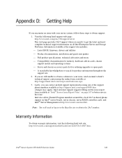
...If you are still unable to obtain a solution to your server system, follow these steps to obtain support: 1. Compatibility documentation for memory, hardware add-in to the Reseller site to get the latest...intel.com/scripts-emf/welcome.aspx 3. Latest BIOS, firmware, drivers and utilities - Intel customer support suggests filling out the issue report form available at http://www.intel.com/reseller/. Product documentation, installation and quick start guides - Server and chassis accessory parts list for product information throughout the support site 2. Intel® Server System SR1600UR...
...If you are still unable to obtain a solution to your server system, follow these steps to obtain support: 1. Compatibility documentation for memory, hardware add-in to the Reseller site to get the latest...intel.com/scripts-emf/welcome.aspx 3. Latest BIOS, firmware, drivers and utilities - Intel customer support suggests filling out the issue report form available at http://www.intel.com/reseller/. Product documentation, installation and quick start guides - Server and chassis accessory parts list for product information throughout the support site 2. Intel® Server System SR1600UR...

Quick Start Guide
Page 1
...DIMM first for buying an Intel® Server System. C Insert DIMM making sure the connector edge of the DIMM aligns correctly with 2 MB cache support. • Memory Type: Minimum of one end of compatible processors and memory, see the Intel® Server System SR1600UR Service Guide, available on... a flat anti-static surface to server board and/or other components. E IMPORTANT! ...
...DIMM first for buying an Intel® Server System. C Insert DIMM making sure the connector edge of the DIMM aligns correctly with 2 MB cache support. • Memory Type: Minimum of one end of compatible processors and memory, see the Intel® Server System SR1600UR Service Guide, available on... a flat anti-static surface to server board and/or other components. E IMPORTANT! ...