
Service Guide
Page 6
... the server system • System fan assembly, including five dual-rotor fans, installed in the server system • Two SATA cables, in hardware box • Processor air duct, installed in the server system • Blue plastic air baffle, installed in the server system • A box of the Intel® Server System SR1560SF: product codes SR1560SF and SR1560SFHS. Intel® Server System SR1560SF - The contents of each server system are...
... the server system • System fan assembly, including five dual-rotor fans, installed in the server system • Two SATA cables, in hardware box • Processor air duct, installed in the server system • Blue plastic air baffle, installed in the server system • A box of the Intel® Server System SR1560SF: product codes SR1560SF and SR1560SFHS. Intel® Server System SR1560SF - The contents of each server system are...

Service Guide
Page 7
Order code: ASR1500PASBP • Active hot-swap backplane. Product Code SR1560SFHS Contents Your Intel® Server System SR1560SF ships with the following kits are available for installing the optical drive component, in the ...blanks, installed in the server system • System fan assembly, including five dual-rotor fans, installed in the server system • Processor air duct, installed in the server system • Blue plastic air baffle, installed in the server system • Intel® Server Deployment Toolkit 2.0 CD • Intel® System Management Software CD Note:...
Order code: ASR1500PASBP • Active hot-swap backplane. Product Code SR1560SFHS Contents Your Intel® Server System SR1560SF ships with the following kits are available for installing the optical drive component, in the ...blanks, installed in the server system • System fan assembly, including five dual-rotor fans, installed in the server system • Processor air duct, installed in the server system • Blue plastic air baffle, installed in the server system • Intel® Server Deployment Toolkit 2.0 CD • Intel® System Management Software CD Note:...

Service Guide
Page 13
...SR1560SFHS Contents vii Safety Information ...ix Important Safety Instructions ix Wichtige Sicherheitshinweise ix Consignes de sécurité ...ix Instrucciones de seguridad importantes ix Chapter 1: Server System References 1 Chapter 2: Server System Features 3 Cable Routing (Hot-Swap Drive System 6 Cable Routing (Fixed Drive System... System Cover 22 Removing the System Cover 22 Installing the System Cover 23 Removing and Installing the Processor Air Duct 24 Intel® Server System SR1560SF Service Guide xiii Product Code SR1560SF Contents vi Intel® Server System ...
...SR1560SFHS Contents vii Safety Information ...ix Important Safety Instructions ix Wichtige Sicherheitshinweise ix Consignes de sécurité ...ix Instrucciones de seguridad importantes ix Chapter 1: Server System References 1 Chapter 2: Server System Features 3 Cable Routing (Hot-Swap Drive System 6 Cable Routing (Fixed Drive System... System Cover 22 Removing the System Cover 22 Installing the System Cover 23 Removing and Installing the Processor Air Duct 24 Intel® Server System SR1560SF Service Guide xiii Product Code SR1560SF Contents vi Intel® Server System ...

Service Guide
Page 14
... Duct 24 Installing and Removing Memory 25 Installing DIMMs ...27 Removing DIMMs ...27 Installing the Processor 28 Installing the Heat Sink(s 29 Removing a Processor 30 Removing and Installing the Small Air Baffle 30 Removing the Small Air Baffle 31 Installing the Small Air ...the Backplane Board 45 Replacing the Fan Board (Fixed Drive System Only 46 Removing the Fan Board 46 Installing the Fan Board 47 Replacing the Server Board 47 Removing the Server Board 47 Installing the Server Board 49 Replacing the Backup Battery 50 xiv Intel® Server System SR1560SF Service Guide
... Duct 24 Installing and Removing Memory 25 Installing DIMMs ...27 Removing DIMMs ...27 Installing the Processor 28 Installing the Heat Sink(s 29 Removing a Processor 30 Removing and Installing the Small Air Baffle 30 Removing the Small Air Baffle 31 Installing the Small Air ...the Backplane Board 45 Replacing the Fan Board (Fixed Drive System Only 46 Removing the Fan Board 46 Installing the Fan Board 47 Replacing the Server Board 47 Removing the Server Board 47 Installing the Server Board 49 Replacing the Backup Battery 50 xiv Intel® Server System SR1560SF Service Guide

Service Guide
Page 19
... Drive Assembly into the Server System 39 Intel® Server System SR1560SF Service Guide xix BIOS Select Jumper 10 Figure 7. Removing the Drive Blank from the Server System 32 Figure 30. Light Guided Diagnostic LEDs 12 Figure 9. Server System Back 17 Figure 13. Installing the Server System Cover 23 Figure 18. Installing the Processor 28 Figure 25. Intel® Server System SR1560SF 3 Figure 2. only if...
... Drive Assembly into the Server System 39 Intel® Server System SR1560SF Service Guide xix BIOS Select Jumper 10 Figure 7. Removing the Drive Blank from the Server System 32 Figure 30. Light Guided Diagnostic LEDs 12 Figure 9. Server System Back 17 Figure 13. Installing the Server System Cover 23 Figure 18. Installing the Processor 28 Figure 25. Intel® Server System SR1560SF 3 Figure 2. only if...

Service Guide
Page 26
... for stacked DDR2 667/800 MHz FBDIMM memory Intel® 5400 Chipset, consisting of the server system. Table 2. Intel® Server System SR1560SF Feature Summary Feature Dimensions Server Board Processor Memory Chipset Peripheral Interfaces I /O Controller Hub External... connections: • Stacked PS/2* ports for keyboard and mouse • RJ45 Serial B port • Two RJ45 NIC connectors for 10/100/1000 Mb...
... for stacked DDR2 667/800 MHz FBDIMM memory Intel® 5400 Chipset, consisting of the server system. Table 2. Intel® Server System SR1560SF Feature Summary Feature Dimensions Server Board Processor Memory Chipset Peripheral Interfaces I /O Controller Hub External... connections: • Stacked PS/2* ports for keyboard and mouse • RJ45 Serial B port • Two RJ45 NIC connectors for 10/100/1000 Mb...

Service Guide
Page 30
... components. Control panel K. System Components 8 Intel® Server System SR1560SF Service Guide Internal Components C B D E F G A M L K J A H I . Rack handles B. Slimline Optical Drive Bay (drive not included) M. hot-swap drive system (drives not included) L. Chassis Component Identification This section helps you can also use the Quick Reference Label provided on the inside of your server system. Power supply D. Processor air duct H. Fan...
... components. Control panel K. System Components 8 Intel® Server System SR1560SF Service Guide Internal Components C B D E F G A M L K J A H I . Rack handles B. Slimline Optical Drive Bay (drive not included) M. hot-swap drive system (drives not included) L. Chassis Component Identification This section helps you can also use the Quick Reference Label provided on the inside of your server system. Power supply D. Processor air duct H. Fan...

Service Guide
Page 31
... EF G II HH GG FF DD BB EE CC AA H Z I . Processor 1 Socket K. SATA 3 AA. Server Board Connector and Component Locations Intel® Server System SR1560SF Service Guide 9 External IO Connectors B. SSI 24-pin Control Panel Header N. Power Supply Management Connector T. Intel® RMM2 NIC Connector D. System Identification LED - Fan Board Connector P. POST Code Diagnostic LEDs F. Serial 'A' Header...
... EF G II HH GG FF DD BB EE CC AA H Z I . Processor 1 Socket K. SATA 3 AA. Server Board Connector and Component Locations Intel® Server System SR1560SF Service Guide 9 External IO Connectors B. SSI 24-pin Control Panel Header N. Power Supply Management Connector T. Intel® RMM2 NIC Connector D. System Identification LED - Fan Board Connector P. POST Code Diagnostic LEDs F. Serial 'A' Header...

Service Guide
Page 34
... G. 5VSB LED 12 Intel® Server System SR1560SF Service Guide Intel® Light Guided Diagnostics The server board contains numerous LEDs providing the following functions: • Fault LEDs help identify failed and failing components. A B C D G E F AF002160 Figure 8. Status LED D. The fault LEDs turn on (amber) if there is a memory or processor fault. • The System Status LED that...
... G. 5VSB LED 12 Intel® Server System SR1560SF Service Guide Intel® Light Guided Diagnostics The server board contains numerous LEDs providing the following functions: • Fault LEDs help identify failed and failing components. A B C D G E F AF002160 Figure 8. Status LED D. The fault LEDs turn on (amber) if there is a memory or processor fault. • The System Status LED that...

Service Guide
Page 46
... Installing the Processor Air Duct Turn processor air duct over the two processor sockets. Removing the Processor Air Duct Lift the processor air duct from its location over to reveal underside. Notes: Do not remove the air dam if only one processor is required for proper airflow within the server system. If two processors are installed) 24 Intel® Server System SR1560SF...
... Installing the Processor Air Duct Turn processor air duct over the two processor sockets. Removing the Processor Air Duct Lift the processor air duct from its location over to reveal underside. Notes: Do not remove the air dam if only one processor is required for proper airflow within the server system. If two processors are installed) 24 Intel® Server System SR1560SF...

Service Guide
Page 47
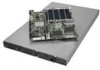
See "Server System References" for a link to the list of tested DIMMs. Figure 21 shows the supported DIMM configuration that may be near or under the air duct. ... from the center of the board. Installing the Processor Air Duct Installing and Removing Memory The silkscreen on the board for a discussion of the air duct should contact the fan module. AF002363 Figure 20. Place the processor air duct over the processor sockets. Intel® Server System SR1560SF Service Guide 25 Use caution not to operate...
See "Server System References" for a link to the list of tested DIMMs. Figure 21 shows the supported DIMM configuration that may be near or under the air duct. ... from the center of the board. Installing the Processor Air Duct Installing and Removing Memory The silkscreen on the board for a discussion of the air duct should contact the fan module. AF002363 Figure 20. Place the processor air duct over the processor sockets. Intel® Server System SR1560SF Service Guide 25 Use caution not to operate...

Service Guide
Page 49
... risk of the DIMM with the metal chassis to the processor by the edges, lift it from the socket, and store it from its anti-static package and position the DIMM above the socket. Intel® Server System SR1560SF Service Guide 27 The arrow in the inset in ...Figure 22 is inserted, push down on the bottom edge of electrostatic discharge (ESD) damage to dissipate the static charge while handling the processor. (2) Avoid moving around unnecessarily. E C D ...
... risk of the DIMM with the metal chassis to the processor by the edges, lift it from the socket, and store it from its anti-static package and position the DIMM above the socket. Intel® Server System SR1560SF Service Guide 27 The arrow in the inset in ...Figure 22 is inserted, push down on the bottom edge of electrostatic discharge (ESD) damage to dissipate the static charge while handling the processor. (2) Avoid moving around unnecessarily. E C D ...

Service Guide
Page 50
Raise the CPU load plate (see Figure 23). A B Figure 24. Installing the Processor TP02075 Note: Do not touch the socket pins; Lifting the Processor Socket Handle 2. they are very sensitive and easily damaged. 28 Intel® Server System SR1560SF Service Guide Installing the Processor 1. Locate the processor socket and raise the socket handle completely (see Figure 24). TP02074 Figure 23.
Raise the CPU load plate (see Figure 23). A B Figure 24. Installing the Processor TP02075 Note: Do not touch the socket pins; Lifting the Processor Socket Handle 2. they are very sensitive and easily damaged. 28 Intel® Server System SR1560SF Service Guide Installing the Processor 1. Locate the processor socket and raise the socket handle completely (see Figure 24). TP02074 Figure 23.
Service Guide
Page 51
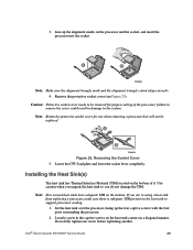
...Intel® Server System SR1560SF Service Guide 29 A B TP02084 Note: Make sure the alignment triangle mark and the alignment triangle cutout align correctly. 4. Remove the protective socket cover (see Figure 25). Note: Retain the protective socket cover for proper cooling of it. Set the heat sink over the processor..., lining up the alignment marks on the processor and the socket, and insert the processor into the socket. Loosely screw in the captive screws on the bottom. failure to ...
...Intel® Server System SR1560SF Service Guide 29 A B TP02084 Note: Make sure the alignment triangle mark and the alignment triangle cutout align correctly. 4. Remove the protective socket cover (see Figure 25). Note: Retain the protective socket cover for proper cooling of it. Set the heat sink over the processor..., lining up the alignment marks on the processor and the socket, and insert the processor into the socket. Loosely screw in the captive screws on the bottom. failure to ...

Service Guide
Page 52
...Heat Sink Shown) Removing a Processor 1. Removing and Installing the Small Air Baffle Some installation processes will require that you remove the small air baffle that is necessary for a component installation process. 30 Intel® Server System SR1560SF Service Guide Gradually and ...equally tighten each captive screw until each is firmly tightened. 2 3 4 1 AF002386 Figure 26. Doing so could damage the processor. 4. 3. Lift the processor lever. 5.
...Heat Sink Shown) Removing a Processor 1. Removing and Installing the Small Air Baffle Some installation processes will require that you remove the small air baffle that is necessary for a component installation process. 30 Intel® Server System SR1560SF Service Guide Gradually and ...equally tighten each captive screw until each is firmly tightened. 2 3 4 1 AF002386 Figure 26. Doing so could damage the processor. 4. 3. Lift the processor lever. 5.

Service Guide
Page 69
Lower the fan board into the Server System 4. If installed, remove the PCI riser assembly. 5. Intel® Server System SR1560SF Service Guide 47 Installing the Fan Board 1. If installed, remove memory, processor heat sinks, and processors from the server board. Connect power to the fan board. Installing the Fan Board into the system (see letter "C"). 3. Connect fan cables to the...
Lower the fan board into the Server System 4. If installed, remove the PCI riser assembly. 5. Intel® Server System SR1560SF Service Guide 47 Installing the Fan Board 1. If installed, remove memory, processor heat sinks, and processors from the server board. Connect power to the fan board. Installing the Fan Board into the system (see letter "C"). 3. Connect fan cables to the...

Service Guide
Page 71
... Server Board 1. Install the system fan assembly. 5. Installing the Server Board AF002347 3. B A Figure 55. Install memory, processor heat sinks, and processors. 9. Install the PCI riser assembly. 7. Install the CPU air duct and blue air baffle. Intel® Server System SR1560SF Service Guide 49 Attach the server board with seven screws (see letter "A"). 2. Re-connect all SATA cables to the server...
... Server Board 1. Install the system fan assembly. 5. Installing the Server Board AF002347 3. B A Figure 55. Install memory, processor heat sinks, and processors. 9. Install the PCI riser assembly. 7. Install the CPU air duct and blue air baffle. Intel® Server System SR1560SF Service Guide 49 Attach the server board with seven screws (see letter "A"). 2. Re-connect all SATA cables to the server...

Service Guide
Page 94
...Checkpoint Diagnostic LED Decoder Description G=Green, R=Red, A=Amber MSB LSB Host Processor 0x10h OFF OFF OFF R Power-on initialization of the host processor (bootstrap processor) 0x11h OFF OFF OFF A Host processor cache initialization (including AP) 0x12h OFF OFF G R Starting application processor initialization 0x13h OFF OFF G A SMM initialization Chipset 0x21h OFF OFF R ... G A OFF Optimizing memory controller settings 0x27h OFF G A G Initializing memory, such as ECC init 0x28h G OFF R OFF Testing memory 72 Intel® Server System SR1560SF Service Guide
...Checkpoint Diagnostic LED Decoder Description G=Green, R=Red, A=Amber MSB LSB Host Processor 0x10h OFF OFF OFF R Power-on initialization of the host processor (bootstrap processor) 0x11h OFF OFF OFF A Host processor cache initialization (including AP) 0x12h OFF OFF G R Starting application processor initialization 0x13h OFF OFF G A SMM initialization Chipset 0x21h OFF OFF R ... G A OFF Optimizing memory controller settings 0x27h OFF G A G Initializing memory, such as ECC init 0x28h G OFF R OFF Testing memory 72 Intel® Server System SR1560SF Service Guide

Service Guide
Page 134
...hot-plug power supply, unplug the power cord to manufacturer for servicing. • Power down the server and disconnect all power cords before adding or replacing any installed processor(s) and heat sink(s) may be installed according to off. • Disconnect the AC power by unplugging...this product. • Turn off all cables and telecommunication lines that are no serviceable parts in it. 112 Intel® Server System SR1560SF Service Guide System Access Warnings Caution: To avoid personal injury or property damage, the following safety instructions apply whenever accessing the ...
...hot-plug power supply, unplug the power cord to manufacturer for servicing. • Power down the server and disconnect all power cords before adding or replacing any installed processor(s) and heat sink(s) may be installed according to off. • Disconnect the AC power by unplugging...this product. • Turn off all cables and telecommunication lines that are no serviceable parts in it. 112 Intel® Server System SR1560SF Service Guide System Access Warnings Caution: To avoid personal injury or property damage, the following safety instructions apply whenever accessing the ...