User Guide
Page 5
..."getting help" information, and the warranty. In this server system. Information about the specific BIOS settings and screens is written for installing or replacing components such as the fans, power supply, drives, and other components. This document provides reference information... how to the Intel® 5000 Series Chipsets Server Board Family Datasheet. Chapter 3 provides instructions on using the Intel® Server System SR1550AL. See "Server System References" for purchasing and using the utilities that give additional details on the server system. Use this chapter...
..."getting help" information, and the warranty. In this server system. Information about the specific BIOS settings and screens is written for installing or replacing components such as the fans, power supply, drives, and other components. This document provides reference information... how to the Intel® 5000 Series Chipsets Server Board Family Datasheet. Chapter 3 provides instructions on using the Intel® Server System SR1550AL. See "Server System References" for purchasing and using the utilities that give additional details on the server system. Use this chapter...

User Guide
Page 6
Product Contents The Intel® Server System SR1550AL ships with the following items: • Intel® Server Board S5000PAL, installed in the server system • One 650 W power supply module, installed in the server system • A box of hardware components, referred to below as the "hardware box" • Full and low profile riser, installed in the server system • Optical drive tray assembly •...
Product Contents The Intel® Server System SR1550AL ships with the following items: • Intel® Server Board S5000PAL, installed in the server system • One 650 W power supply module, installed in the server system • A box of hardware components, referred to below as the "hardware box" • Full and low profile riser, installed in the server system • Optical drive tray assembly •...
User Guide
Page 12
... Filler into the Server System 71 Figure 65. Removing a System Fan 72 Figure 66. Figure 42. Removing the Intel® RMM and the Intel® RMM NIC Module from the Server System 64 Figure 55. Removing Power Supply Filler Panel from the Server System 51 Figure 45.... from the Server System 71 Figure 64. Installing the Power Distribution Board Cover 67 Figure 59. System Cable Routing 85 Figure 74. SATA Cable Installation 86 Figure 75. Diagnostic LED Placement Diagram 106 xii Intel® Server System SR1550AL/SR1550ALSAS User's Guide Installing a System Fan 73 Figure...
... Filler into the Server System 71 Figure 65. Removing a System Fan 72 Figure 66. Figure 42. Removing the Intel® RMM and the Intel® RMM NIC Module from the Server System 64 Figure 55. Removing Power Supply Filler Panel from the Server System 51 Figure 45.... from the Server System 71 Figure 64. Installing the Power Distribution Board Cover 67 Figure 59. System Cable Routing 85 Figure 74. SATA Cable Installation 86 Figure 75. Diagnostic LED Placement Diagram 106 xii Intel® Server System SR1550AL/SR1550ALSAS User's Guide Installing a System Fan 73 Figure...
User Guide
Page 15
...Single Power Supply Input Voltages 86 750W Single Power Supply Output Voltages 87 System Environmental Specifications 88 Appendix B: Troubleshooting 89 Resetting the System ...89 Problems following Initial System ...Installation 90 First Steps Checklist ...90 Hardware Diagnostic Testing 91 Verifying Proper Operation of Key System Lights 91 Confirming Loading of the Operating System 91 Specific Problems and Corrective Actions 92 Power Light Does Not Light 92 No Characters Appear on Screen 93 Characters Are Distorted or Incorrect 93 Intel® Server System SR1550AL/SR1550ALSAS...
...Single Power Supply Input Voltages 86 750W Single Power Supply Output Voltages 87 System Environmental Specifications 88 Appendix B: Troubleshooting 89 Resetting the System ...89 Problems following Initial System ...Installation 90 First Steps Checklist ...90 Hardware Diagnostic Testing 91 Verifying Proper Operation of Key System Lights 91 Confirming Loading of the Operating System 91 Specific Problems and Corrective Actions 92 Power Light Does Not Light 92 No Characters Appear on Screen 93 Characters Are Distorted or Incorrect 93 Intel® Server System SR1550AL/SR1550ALSAS...

User Guide
Page 19
... Menu Key Use 80 Table 5. Product Regulatory Compliance Markings 117 Intel® Server System SR1550AL/SR1550ALSAS User's Guide xix Power Supply Output Capability 87 Table 6. POST Progress Code LED Example 105 Table 12. POST Error Beep Codes 98 Table 10. Server System References 1 Table 2. Error Beep Codes Generated by Intel® Remote Management Module 99 Table 11. NIC LED...
... Menu Key Use 80 Table 5. Product Regulatory Compliance Markings 117 Intel® Server System SR1550AL/SR1550ALSAS User's Guide xix Power Supply Output Capability 87 Table 6. POST Progress Code LED Example 105 Table 12. POST Error Beep Codes 98 Table 10. Server System References 1 Table 2. Error Beep Codes Generated by Intel® Remote Management Module 99 Table 11. NIC LED...

User Guide
Page 25
... • LCD Display Up to two 650W power supply modules • Six 4-pin fan headers supporting two processor fans, and four system fans • Dedicated non-redundant power supply fan (one per module) • One front panel USB port • One internal USB header providing two USB ports Intel® System Management Software Intel® Server System SR1550AL/SR1550ALSAS User's Guide 5
... • LCD Display Up to two 650W power supply modules • Six 4-pin fan headers supporting two processor fans, and four system fans • Dedicated non-redundant power supply fan (one per module) • One front panel USB port • One internal USB header providing two USB ports Intel® System Management Software Intel® Server System SR1550AL/SR1550ALSAS User's Guide 5
User Guide
Page 26
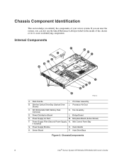
... to assist in identifying components. Slimline Optical Drive Bay (Optical Drive Shown) J. Fan Assembly D. Mini Control Panel Bay if Installed) G. Server Board P. Power Supply Air Duct M. PCI Riser Assembly B. Internal Components F G E H I . Mid-plane Board (Active Shown) F. ChassisComponents 6 Intel® Server System SR1550AL/SR1550ALSAS User's Guide Processor Air Duct C. Power Distribution Board L. Bridge Board E. Power Supply Module O. Hard Drive Bays Figure 2.
... to assist in identifying components. Slimline Optical Drive Bay (Optical Drive Shown) J. Fan Assembly D. Mini Control Panel Bay if Installed) G. Server Board P. Power Supply Air Duct M. PCI Riser Assembly B. Internal Components F G E H I . Mid-plane Board (Active Shown) F. ChassisComponents 6 Intel® Server System SR1550AL/SR1550ALSAS User's Guide Processor Air Duct C. Power Distribution Board L. Bridge Board E. Power Supply Module O. Hard Drive Bays Figure 2.

User Guide
Page 31
Low Profile PCI Express* Add-in Card Slot E. NIC 1 (10/100/1000 Mb) N. Keyboard Figure 7. Full Height PCI Add-in Card Slot D. Intel® Remote Management Module NIC (Optional) H. Video L. RJ45 Serial B Connector B. USB Port 5 J. I/O Expansion Module (Optional) I. Power Supply Module 1 F. Power Supply Module 2 (Filler Panel Shown) G. Mouse C. USB Port 6 K. NIC 2 (10/100/1000 Mb) M. Back Panel Connectors Intel® Server System SR1550AL/SR1550ALSAS User's Guide 11 Back Panel Connectors A B C D NML K J IH GF E TP02216 A.
Low Profile PCI Express* Add-in Card Slot E. NIC 1 (10/100/1000 Mb) N. Keyboard Figure 7. Full Height PCI Add-in Card Slot D. Intel® Remote Management Module NIC (Optional) H. Video L. RJ45 Serial B Connector B. USB Port 5 J. I/O Expansion Module (Optional) I. Power Supply Module 1 F. Power Supply Module 2 (Filler Panel Shown) G. Mouse C. USB Port 6 K. NIC 2 (10/100/1000 Mb) M. Back Panel Connectors Intel® Server System SR1550AL/SR1550ALSAS User's Guide 11 Back Panel Connectors A B C D NML K J IH GF E TP02216 A.
User Guide
Page 84
... the AC power cord from the Server System 5. TP02242 Figure 54. Removing Power Supply Filler Panel from the system or wall outlet. If a power supply is installed, release the latch (see "Removing the Chassis Cover". 4. Power down the server and unplug all peripheral devices connected to remove the filler panel as shown in the figure below . 64 Intel® Server System SR1550AL/SR1550ALSAS User...
... the AC power cord from the Server System 5. TP02242 Figure 54. Removing Power Supply Filler Panel from the system or wall outlet. If a power supply is installed, release the latch (see "Removing the Chassis Cover". 4. Power down the server and unplug all peripheral devices connected to remove the filler panel as shown in the figure below . 64 Intel® Server System SR1550AL/SR1550ALSAS User...

User Guide
Page 85
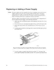
TP02243 Figure 56. Intel® Server System SR1550AL/SR1550ALSAS User's Guide 65 Install the server system cover. Plug all peripheral devices and the AC power cable into place. Insert the replacement power supply module into the power supply cage until it clicks into the server. Installing Power Supply Module into the Server System 7. For instructions, see "Installing the Server System Cover". 9. B A TP02244 Figure 55. Removing Power Supply Module from the Server System 6. If no power supply is to be installed, insert a power supply filler panel. 8.
TP02243 Figure 56. Intel® Server System SR1550AL/SR1550ALSAS User's Guide 65 Install the server system cover. Plug all peripheral devices and the AC power cable into place. Insert the replacement power supply module into the power supply cage until it clicks into the server. Installing Power Supply Module into the Server System 7. For instructions, see "Installing the Server System Cover". 9. B A TP02244 Figure 55. Removing Power Supply Module from the Server System 6. If no power supply is to be installed, insert a power supply filler panel. 8.

User Guide
Page 86
... to release the power distribution board cover (see "Replacing or Adding a Power Supply". 5. See "Safety Information". 2. Install a new power distribution board by sliding the board to the system boards. 66 Intel® Server System SR1550AL/SR1550ALSAS User's Guide Replacing the Power Distribution Module To replace the power distribution module, use the following instructions. 1. Remove the server system cover. Removing the Power Distribution Board Cover...
... to release the power distribution board cover (see "Replacing or Adding a Power Supply". 5. See "Safety Information". 2. Install a new power distribution board by sliding the board to the system boards. 66 Intel® Server System SR1550AL/SR1550ALSAS User's Guide Replacing the Power Distribution Module To replace the power distribution module, use the following instructions. 1. Remove the server system cover. Removing the Power Distribution Board Cover...

User Guide
Page 87
Installing the Power Distribution Board Cover 12. For instructions, see "Replacing or Adding a Power Supply". 13. Install the power distribution board cover and screw it into the server. For instructions, see "Installing the Server System Cover". 14. Plug all peripheral devices and the AC power cable into place. Install the hot-swap power supply/supplies. Install the server system cover. B A TP02229 Figure 58. Intel® Server System SR1550AL/SR1550ALSAS User's Guide 67 11.
Installing the Power Distribution Board Cover 12. For instructions, see "Replacing or Adding a Power Supply". 13. Install the power distribution board cover and screw it into the server. For instructions, see "Installing the Server System Cover". 14. Plug all peripheral devices and the AC power cable into place. Install the hot-swap power supply/supplies. Install the server system cover. B A TP02229 Figure 58. Intel® Server System SR1550AL/SR1550ALSAS User's Guide 67 11.

User Guide
Page 92
...as shown in the power supply fails, the power supply must first take the server out of the fans in the figure below to loosen. A B TP02266 Figure 65. Replacing a System Fan Caution: The system fans are integrated into the power supply cannot be replaced ...system by pressing the power button, and unplug the AC power cord from the module as shown in the figure below (see letter "B"). Lift the failed fan from the system or wall outlet. Power down . 72 Intel® Server System SR1550AL/SR1550ALSAS User's Guide The system fans at the front of the Intel® Server System...
...as shown in the power supply fails, the power supply must first take the server out of the fans in the figure below to loosen. A B TP02266 Figure 65. Replacing a System Fan Caution: The system fans are integrated into the power supply cannot be replaced ...system by pressing the power button, and unplug the AC power cord from the module as shown in the figure below (see letter "B"). Lift the failed fan from the system or wall outlet. Power down . 72 Intel® Server System SR1550AL/SR1550ALSAS User's Guide The system fans at the front of the Intel® Server System...

User Guide
Page 105
... server system cover. System Cable Routing TP02250 A Intel® Remote Management Module (optional) B Intel® RMM NIC Module (optional) C I/O Module (optional) D Power Supply E Bridge Board F Mid-plane Board (active shown) G Power Distribution Board H Backplane Board I O J N F H Figure 73. Use the figures below to Mid-plane BC A D M G L E K I Power to Mid-plane Board J Power to Backplane Board K Power to Server Board (CPU) L Power to Server Board (Main) M Power...
... server system cover. System Cable Routing TP02250 A Intel® Remote Management Module (optional) B Intel® RMM NIC Module (optional) C I/O Module (optional) D Power Supply E Bridge Board F Mid-plane Board (active shown) G Power Distribution Board H Backplane Board I O J N F H Figure 73. Use the figures below to Mid-plane BC A D M G L E K I Power to Mid-plane Board J Power to Backplane Board K Power to Server Board (CPU) L Power to Server Board (Main) M Power...

User Guide
Page 106
0 1 A 2 3 4 5 4567 B 0 1 2 3 A Figure 74. SATA Cable Installation TP02249 750W Single Power Supply Input Voltages • 100-127V at 50/60 Hz; 12 A max. • 200-240V at 50/60 Hz; 6 A max. 86 Intel® Server System SR1550AL/SR1550ALSAS User's Guide
0 1 A 2 3 4 5 4567 B 0 1 2 3 A Figure 74. SATA Cable Installation TP02249 750W Single Power Supply Input Voltages • 100-127V at 50/60 Hz; 12 A max. • 200-240V at 50/60 Hz; 6 A max. 86 Intel® Server System SR1550AL/SR1550ALSAS User's Guide

User Guide
Page 107
Intel® Server System SR1550AL/SR1550ALSAS User's Guide 87 Power Supply Output Capability Voltage +3.3 V +5.0 V +5 V Standby +12.0 -12.0 V 36 A 45 A 20 A 2.0 A Maximum Current Warning: Do not exceed a combined power output of 750 Watts. For information about calculating the power usage for your loads do not exceed the combined total wattage of 90 Watts for each voltage. 750W Single Power Supply Output Voltages...
Intel® Server System SR1550AL/SR1550ALSAS User's Guide 87 Power Supply Output Capability Voltage +3.3 V +5.0 V +5 V Standby +12.0 -12.0 V 36 A 45 A 20 A 2.0 A Maximum Current Warning: Do not exceed a combined power output of 750 Watts. For information about calculating the power usage for your loads do not exceed the combined total wattage of 90 Watts for each voltage. 750W Single Power Supply Output Voltages...
User Guide
Page 110
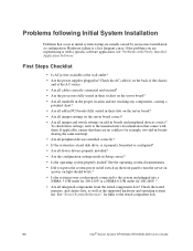
...server on (power on light should be lit)? • Is the system power cord properly connected to the system and plugged into a NEMA 5 15R outlet for 100-120V or a NEMA 6-15R outlet for links to the manufacturer's documentation that occur at the wall outlet? • Are the power supplies...Setup correct? • Is the operating system properly loaded? To check these settings, refer to the tested component lists. 90 Intel® Server System SR1550AL/SR1550ALSAS User's Guide First Steps Checklist • Is AC power available at initial system startup are no conflicts-for example, two...
...server on (power on light should be lit)? • Is the system power cord properly connected to the system and plugged into a NEMA 5 15R outlet for 100-120V or a NEMA 6-15R outlet for links to the manufacturer's documentation that occur at the wall outlet? • Are the power supplies...Setup correct? • Is the operating system properly loaded? To check these settings, refer to the tested component lists. 90 Intel® Server System SR1550AL/SR1550ALSAS User's Guide First Steps Checklist • Is AC power available at initial system startup are no conflicts-for example, two...
User Guide
Page 112
... plugged the server AC power cord into the power supply? • Some ATX power supplies have been populated according to the server board might be loose. • Have you press the power-on button? • Is the system operating normally? If so, the power LED might be...system requirements. • Remove the memory DIMMs and re-seat them . • Make sure the chassis standoffs are problems with the system requirements. • Make sure the processor(s) have a power switch on the back of the server board and cause a short. 92 Intel® Server System SR1550AL/SR1550ALSAS...
... plugged the server AC power cord into the power supply? • Some ATX power supplies have been populated according to the server board might be loose. • Have you press the power-on button? • Is the system operating normally? If so, the power LED might be...system requirements. • Remove the memory DIMMs and re-seat them . • Make sure the chassis standoffs are problems with the system requirements. • Make sure the processor(s) have a power switch on the back of the server board and cause a short. 92 Intel® Server System SR1550AL/SR1550ALSAS...

User Guide
Page 114
... the both the control panel board and to the server board? • Are the power supply cables properly connected to an overheating situation? • Have your system has LED lights for the fans, is an indication of possible system component failure. If so, the signal cable may ... • Is the drive properly configured? 94 Intel® Server System SR1550AL/SR1550ALSAS User's Guide If not, see "Power Light Does Not Light". • If your fans speeded up in incorrectly. System Cooling Fans Do Not Rotate Properly If the system cooling fans are not operating properly, it is one...
... the both the control panel board and to the server board? • Are the power supply cables properly connected to an overheating situation? • Have your system has LED lights for the fans, is an indication of possible system component failure. If so, the signal cable may ... • Is the drive properly configured? 94 Intel® Server System SR1550AL/SR1550ALSAS User's Guide If not, see "Power Light Does Not Light". • If your fans speeded up in incorrectly. System Cooling Fans Do Not Rotate Properly If the system cooling fans are not operating properly, it is one...
User Guide
Page 117
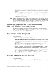
...Intel® Server System SR1550AL/SR1550ALSAS User's Guide 97 Note: Random errors in data files: If you are getting corrupted by voltage spikes on your power line. See "Server System References" for the Intel® chipsets, onboard NICs, and other random component failures. • If you suspect that a transient voltage spike, power... is connected correctly and that is plugged into the power supply. • Make sure the drive is compatible. If you are experiencing any of the above symptoms that might have not exceeded the power budget for details on setting the master/slave settings...
...Intel® Server System SR1550AL/SR1550ALSAS User's Guide 97 Note: Random errors in data files: If you are getting corrupted by voltage spikes on your power line. See "Server System References" for the Intel® chipsets, onboard NICs, and other random component failures. • If you suspect that a transient voltage spike, power... is connected correctly and that is plugged into the power supply. • Make sure the drive is compatible. If you are experiencing any of the above symptoms that might have not exceeded the power budget for details on setting the master/slave settings...
