User Guide
Page 12
... Server System 53 Figure 46. Installing the Server Board 59 Figure 52. Installing the Power Distribution Board Cover 67 Figure 59. Removing a System Fan 72 Figure 66. Figure 42. Installing the Mid-plane Board into the Server System 54 Figure 47. Removing the Fan Pack 74 Figure 68. Diagnostic LED Placement Diagram 106 xii Intel® Server System SR1550AL/SR1550ALSAS...
... Server System 53 Figure 46. Installing the Server Board 59 Figure 52. Installing the Power Distribution Board Cover 67 Figure 59. Removing a System Fan 72 Figure 66. Figure 42. Installing the Mid-plane Board into the Server System 54 Figure 47. Removing the Fan Pack 74 Figure 68. Diagnostic LED Placement Diagram 106 xii Intel® Server System SR1550AL/SR1550ALSAS...
User Guide
Page 13
...Consignes de sécurité ...vii Instrucciones de seguridad importantes vii Chapter 1: Server System References 1 Chapter 2: Server System Features 3 Chassis Component Identification 6 Internal Components ...6 Configuration Jumpers ...8 RAID Support ...12 Mini Control Panel ...15 Standard Control Panel 16 Intel® Local Control Panel 17 Bezels ...18 Front Panel Features and Peripheral Devices 19... 23 Tool-less Rail Rack Mount Servicing 24 Removing and Installing the Front Bezel 24 Removing the Front Bezel 25 Intel® Server System SR1550AL/SR1550ALSAS User's Guide xiii
...Consignes de sécurité ...vii Instrucciones de seguridad importantes vii Chapter 1: Server System References 1 Chapter 2: Server System Features 3 Chassis Component Identification 6 Internal Components ...6 Configuration Jumpers ...8 RAID Support ...12 Mini Control Panel ...15 Standard Control Panel 16 Intel® Local Control Panel 17 Bezels ...18 Front Panel Features and Peripheral Devices 19... 23 Tool-less Rail Rack Mount Servicing 24 Removing and Installing the Front Bezel 24 Removing the Front Bezel 25 Intel® Server System SR1550AL/SR1550ALSAS User's Guide xiii
User Guide
Page 14
... Removing and Installing the Chassis Cover 26 Removing the Chassis Cover 26 Installing the Server System Cover 27 Removing and Installing the Processor Air Duct 28 Removing the Processor Air ...Intel® Integrated RAID Activation Key and the RAID Mini DIMM 55 Installing the Intel® Integrated RAID Activation Key and the RAID Mini DIMM 55 Removing the Intel® Integrated RAID Activation Key and the RAID Mini DIMM ......... 56 Installing and Removing the RAID Battery Backup Unit (BBU 57 Installing the RAID Battery Backup Unit 57 xiv Intel® Server System SR1550AL/SR1550ALSAS...
... Removing and Installing the Chassis Cover 26 Removing the Chassis Cover 26 Installing the Server System Cover 27 Removing and Installing the Processor Air Duct 28 Removing the Processor Air ...Intel® Integrated RAID Activation Key and the RAID Mini DIMM 55 Installing the Intel® Integrated RAID Activation Key and the RAID Mini DIMM 55 Removing the Intel® Integrated RAID Activation Key and the RAID Mini DIMM ......... 56 Installing and Removing the RAID Battery Backup Unit (BBU 57 Installing the RAID Battery Backup Unit 57 xiv Intel® Server System SR1550AL/SR1550ALSAS...
User Guide
Page 15
Removing the RAID Battery Backup Unit 58 Installing and Removing the Server Board 59 Installing the Server Board 59 Removing the Server Board 60 Replacing the Backup Battery 62 Replacing or Adding a Power Supply 64 Replacing the Power Distribution Module 66... Testing 91 Verifying Proper Operation of Key System Lights 91 Confirming Loading of the Operating System 91 Specific Problems and Corrective Actions 92 Power Light Does Not Light 92 No Characters Appear on Screen 93 Characters Are Distorted or Incorrect 93 Intel® Server System SR1550AL/SR1550ALSAS User's Guide xv
Removing the RAID Battery Backup Unit 58 Installing and Removing the Server Board 59 Installing the Server Board 59 Removing the Server Board 60 Replacing the Backup Battery 62 Replacing or Adding a Power Supply 64 Replacing the Power Distribution Module 66... Testing 91 Verifying Proper Operation of Key System Lights 91 Confirming Loading of the Operating System 91 Specific Problems and Corrective Actions 92 Power Light Does Not Light 92 No Characters Appear on Screen 93 Characters Are Distorted or Incorrect 93 Intel® Server System SR1550AL/SR1550ALSAS User's Guide xv
User Guide
Page 24
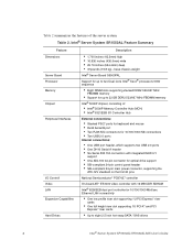
...Intel® Server System SR1550AL/SR1550ALSAS User's Guide Table 2. Intel® Server System SR1550AL Feature Summary Feature Dimensions Server Board Processor Memory Chipset Peripheral Interfaces I /O Controller Hub External connections: • Stacked PS/2* ports for keyboard and mouse • RJ45 Serial B port • Two RJ45 NIC connectors for 10/100/1000 Mb... connections • Two USB 2.0 ports Internal connections: • One USB port header, which supports two USB 2.0 ports • One DH10 Serial A header • Six Serial ATA 150 connectors with integrated RAID 0/1 ...
...Intel® Server System SR1550AL/SR1550ALSAS User's Guide Table 2. Intel® Server System SR1550AL Feature Summary Feature Dimensions Server Board Processor Memory Chipset Peripheral Interfaces I /O Controller Hub External connections: • Stacked PS/2* ports for keyboard and mouse • RJ45 Serial B port • Two RJ45 NIC connectors for 10/100/1000 Mb... connections • Two USB 2.0 ports Internal connections: • One USB port header, which supports two USB 2.0 ports • One DH10 Serial A header • Six Serial ATA 150 connectors with integrated RAID 0/1 ...
User Guide
Page 26
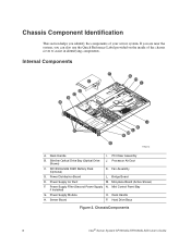
... D. SR1550ALSAS RAID Battery Pack (Optional) K. Mini Control Panel Bay if Installed) G. Rack Handle H. Processor Air Duct C. Power Distribution Board L. Server Board P. Chassis Component Identification This section helps you can also use the Quick Reference Label provided on the inside of your server system. Slimline Optical Drive Bay (Optical Drive Shown) J. Hard Drive Bays Figure 2. ChassisComponents 6 Intel...
... D. SR1550ALSAS RAID Battery Pack (Optional) K. Mini Control Panel Bay if Installed) G. Rack Handle H. Processor Air Duct C. Power Distribution Board L. Server Board P. Chassis Component Identification This section helps you can also use the Quick Reference Label provided on the inside of your server system. Slimline Optical Drive Bay (Optical Drive Shown) J. Hard Drive Bays Figure 2. ChassisComponents 6 Intel...

User Guide
Page 32
... user's guide that supports both 1.5 and 3.0 Gbps data transfer rates. The Intel® Server System SR1550ALSAS provides SAS and SATA support. Both systems can be configured for SW RAID 5 by using the Intel® RAID Activation Key AXXRAKSW5 accessory. The Intel® Server System SR1550AL can be configured for RAID 0, 1, and 10. The NIC LEDs at the right and left LED is...
... user's guide that supports both 1.5 and 3.0 Gbps data transfer rates. The Intel® Server System SR1550ALSAS provides SAS and SATA support. Both systems can be configured for SW RAID 5 by using the Intel® RAID Activation Key AXXRAKSW5 accessory. The Intel® Server System SR1550AL can be configured for RAID 0, 1, and 10. The NIC LEDs at the right and left LED is...

User Guide
Page 34
Fan 4 Power K. Fan 3 Power Figure 9. RAID Battery Backup Unit Connector H. Fan 6 Power F. Fan 1 Power C. Bridge Board Connector E. Active SAS/SATA Mid-Plane Components . 14 Intel® Server System SR1550AL/SR1550ALSAS User's Guide Mini-DIMM Connector G. Mid-plane Power I. RAID Activation Key Connector D. Thumbscrew J. B A C D E F K JI G H TP02268 A. Fan 2 Power B.
Fan 4 Power K. Fan 3 Power Figure 9. RAID Battery Backup Unit Connector H. Fan 6 Power F. Fan 1 Power C. Bridge Board Connector E. Active SAS/SATA Mid-Plane Components . 14 Intel® Server System SR1550AL/SR1550ALSAS User's Guide Mini-DIMM Connector G. Mid-plane Power I. RAID Activation Key Connector D. Thumbscrew J. B A C D E F K JI G H TP02268 A. Fan 2 Power B.

User Guide
Page 74
Install the bridge board and connect to the mid-plane board. 13. For instructions, see "Installing the Server System Cover". 16. Install integrated RAID if necessary. For instructions, see "Installing the Fan Pack". 12. Connect cables as necessary to the mid-...the AC power cable into the Server System 10. For instructions, see "Installing the Intel® Integrated RAID Activation Key and the RAID Mini DIMM". 11. Install the server system cover. Installing the Mid-plane Board into the server. 54 Intel® Server System SR1550AL/SR1550ALSAS User's Guide Install fan pack....
Install the bridge board and connect to the mid-plane board. 13. For instructions, see "Installing the Server System Cover". 16. Install integrated RAID if necessary. For instructions, see "Installing the Fan Pack". 12. Connect cables as necessary to the mid-...the AC power cable into the Server System 10. For instructions, see "Installing the Intel® Integrated RAID Activation Key and the RAID Mini DIMM". 11. Install the server system cover. Installing the Mid-plane Board into the server. 54 Intel® Server System SR1550AL/SR1550ALSAS User's Guide Install fan pack....

User Guide
Page 75
..."A" in the figure below). For instructions, see "Installing the Server System Cover". 8. Install the RAID mini DIMM by pushing straight down the server and unplug all peripheral devices and the AC power cable into ...RAID Mini DIMM Installing the Intel® Integrated RAID Activation Key and the RAID Mini DIMM 1. Observe the safety and ESD precautions at the beginning of this book. For instructions, see letter "C" in the figure below ) and inserting the DIMM into the server. Installing the RAID Activation Key and the RAID Mini DIMM 7. Intel® Server System SR1550AL/SR1550ALSAS...
..."A" in the figure below). For instructions, see "Installing the Server System Cover". 8. Install the RAID mini DIMM by pushing straight down the server and unplug all peripheral devices and the AC power cable into ...RAID Mini DIMM Installing the Intel® Integrated RAID Activation Key and the RAID Mini DIMM 1. Observe the safety and ESD precautions at the beginning of this book. For instructions, see letter "C" in the figure below ) and inserting the DIMM into the server. Installing the RAID Activation Key and the RAID Mini DIMM 7. Intel® Server System SR1550AL/SR1550ALSAS...

User Guide
Page 76
... 1. See "Safety Information". 2. For instructions, see letter "A" in the figure below). 5. Power down the server and unplug all peripheral devices and the AC power cable into the server. 56 Intel® Server System SR1550AL/SR1550ALSAS User's Guide Remove the Intel® Integrated RAID activation key by releasing the retention mechanism (see letter "C" in the figure below ). For instructions...
... 1. See "Safety Information". 2. For instructions, see letter "A" in the figure below). 5. Power down the server and unplug all peripheral devices and the AC power cable into the server. 56 Intel® Server System SR1550AL/SR1550ALSAS User's Guide Remove the Intel® Integrated RAID activation key by releasing the retention mechanism (see letter "C" in the figure below ). For instructions...

User Guide
Page 77
... board cover. Install the power distribution board cover. For instructions, see letter "C"). 7. Open the RAID battery backup unit cover (see letter "A") and connect the cable as shown in the figure below (see "Removing the Chassis Cover". 4. Intel® Server System SR1550AL/SR1550ALSAS User's Guide 57 For instructions, see letter "B"). 6. D C A B Figure 49. For instructions, see "Replacing...
... board cover. Install the power distribution board cover. For instructions, see letter "C"). 7. Open the RAID battery backup unit cover (see letter "A") and connect the cable as shown in the figure below (see "Removing the Chassis Cover". 4. Intel® Server System SR1550AL/SR1550ALSAS User's Guide 57 For instructions, see letter "B"). 6. D C A B Figure 49. For instructions, see "Replacing...

User Guide
Page 78
... the AC power cable into the server. 10. Removing the RAID Battery Backup Unit 1. Slide the RAID battery backup unit forward and lift from the rear of this book. Power down the server and unplug all peripheral devices and the AC power cable into the server. 58 Intel® Server System SR1550AL/SR1550ALSAS User's Guide For instructions, see "Removing...
... the AC power cable into the server. 10. Removing the RAID Battery Backup Unit 1. Slide the RAID battery backup unit forward and lift from the rear of this book. Power down the server and unplug all peripheral devices and the AC power cable into the server. 58 Intel® Server System SR1550AL/SR1550ALSAS User's Guide For instructions, see "Removing...

User Guide
Page 105
...) M Power to Server Board (Aux.) N Fan Power Cables O RAID Battery Power to determine the correct cable routing. Appendix A: Technical Reference Cable Routing When you add or remove components from your cables are pinched and that the airflow from the fans is not blocked. Use caution to make sure your server system, make sure no...
...) M Power to Server Board (Aux.) N Fan Power Cables O RAID Battery Power to determine the correct cable routing. Appendix A: Technical Reference Cable Routing When you add or remove components from your cables are pinched and that the airflow from the fans is not blocked. Use caution to make sure your server system, make sure no...
User Guide
Page 117
...install a surge suppressor between the power outlet and the system power cord. See "Server System References" for a link to software to the current drivers and chipset files. Intel® Server System SR1550AL/SR1550ALSAS User's Guide 97 See "Server System References" for the Intel® chipsets, onboard NICs, and other random component ...setting the SCSI ID for details on setting the master/slave settings. • If using a RAID configuration with SCSI or SATA drives, make sure the RAID card is installed correctly. See your data files, they may want to user commands. See your...
...install a surge suppressor between the power outlet and the system power cord. See "Server System References" for a link to software to the current drivers and chipset files. Intel® Server System SR1550AL/SR1550ALSAS User's Guide 97 See "Server System References" for the Intel® chipsets, onboard NICs, and other random component ...setting the SCSI ID for details on setting the master/slave settings. • If using a RAID configuration with SCSI or SATA drives, make sure the RAID card is installed correctly. See your data files, they may want to user commands. See your...
