User Guide
Page 11
... Figure 1. Mini Control Panel 15 Figure 11. Front Bezel Supporting the Mini Control Panel 25 Figure 17. Installing the Memory 30 Figure 25. Installing the Interposer Board to the Server Board 48 Intel® Server System SR1550AL/SR1550ALSAS User's Guide xi Installing the PCI-X* Riser Card into Carrier 36 Figure 31. Installing the I/O Expansion Module(s) to...
... Figure 1. Mini Control Panel 15 Figure 11. Front Bezel Supporting the Mini Control Panel 25 Figure 17. Installing the Memory 30 Figure 25. Installing the Interposer Board to the Server Board 48 Intel® Server System SR1550AL/SR1550ALSAS User's Guide xi Installing the PCI-X* Riser Card into Carrier 36 Figure 31. Installing the I/O Expansion Module(s) to...
User Guide
Page 14
... 26 Removing the Chassis Cover 26 Installing the Server System Cover 27 Removing and Installing the Processor Air Duct 28 Removing the Processor Air Duct 28 Installing the Processor Air Duct 29 Installing and Removing Memory 30 Installing DIMMs ...30 Removing DIMMs ...31 ...Intel® Integrated RAID Activation Key and the RAID Mini DIMM 55 Removing the Intel® Integrated RAID Activation Key and the RAID Mini DIMM ......... 56 Installing and Removing the RAID Battery Backup Unit (BBU 57 Installing the RAID Battery Backup Unit 57 xiv Intel® Server System SR1550AL/SR1550ALSAS...
... 26 Removing the Chassis Cover 26 Installing the Server System Cover 27 Removing and Installing the Processor Air Duct 28 Removing the Processor Air Duct 28 Installing the Processor Air Duct 29 Installing and Removing Memory 30 Installing DIMMs ...30 Removing DIMMs ...31 ...Intel® Integrated RAID Activation Key and the RAID Mini DIMM 55 Removing the Intel® Integrated RAID Activation Key and the RAID Mini DIMM ......... 56 Installing and Removing the RAID Battery Backup Unit (BBU 57 Installing the RAID Battery Backup Unit 57 xiv Intel® Server System SR1550AL/SR1550ALSAS...
User Guide
Page 24
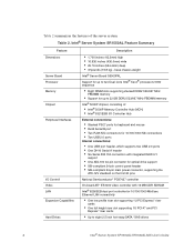
...ATX-12V standard on the first 20 pins National Semiconductor* PC87427 controller On-board ATI* ES1000 video controller with 16 MB DDR SDRAM Intel® 82563EB dual port controller for 10/100/1000 Mbit/sec Ethernet LAN connectivity • One low profile riser... supporting stacked DDR2 533/667 MHz FBDIMM memory • Support for up to eight 2.5 inch hot-swap SATA / SAS drives 4 Intel® Server System SR1550AL/SR1550ALSAS User's Guide Table 2. Table 2 summarizes the features of : • Intel® 5000P Memory Controller Hub (MCH) • Intel® 6321ESB I /O Controll Video LAN...
...ATX-12V standard on the first 20 pins National Semiconductor* PC87427 controller On-board ATI* ES1000 video controller with 16 MB DDR SDRAM Intel® 82563EB dual port controller for 10/100/1000 Mbit/sec Ethernet LAN connectivity • One low profile riser... supporting stacked DDR2 533/667 MHz FBDIMM memory • Support for up to eight 2.5 inch hot-swap SATA / SAS drives 4 Intel® Server System SR1550AL/SR1550ALSAS User's Guide Table 2. Table 2 summarizes the features of : • Intel® 5000P Memory Controller Hub (MCH) • Intel® 6321ESB I /O Controll Video LAN...

User Guide
Page 49
...over to pinch or disengage cables that may be near or under the air duct. 7. Install the server system cover. Installing the Processor Air Duct Intel® Server System SR1550AL/SR1550ALSAS User's Guide 29 See ""Safety Information". 2. TP02227 Figure 22. only if two processors are installed... duct should contact the fan module. Plug all peripheral devices and the AC power cable. 3. For instructions, see "Installing the Server System Cover". 8. Turn processor air duct over the processor socket(s). Removing the Processor 2 Air Dam (Optional - Installing the Processor Air...
...over to pinch or disengage cables that may be near or under the air duct. 7. Install the server system cover. Installing the Processor Air Duct Intel® Server System SR1550AL/SR1550ALSAS User's Guide 29 See ""Safety Information". 2. TP02227 Figure 22. only if two processors are installed... duct should contact the fan module. Plug all peripheral devices and the AC power cable. 3. For instructions, see "Installing the Server System Cover". 8. Turn processor air duct over the processor socket(s). Removing the Processor 2 Air Dam (Optional - Installing the Processor Air...

User Guide
Page 50
... the board for a discussion of the memory requirements and options. See "Memory" for the DIMMs displays DIMM A1, DIMM A2, DIMM B1, DIMM B2, DIMM C1, DIMM C2, DIMM D1 and DIMM D2 starting from the server. 4. See "Server System References" for a link to the server. DIMM B2 Socket DIMM B1 Socket DIMM... DIMM C1 Socket DIMM C2 Socket DIMM D1 Socket DIMM D2 Socket D A C B TP02072 Figure 24. For instructions, see Figure 24). Installing the Memory 30 Intel® Server System SR1550AL/SR1550ALSAS User's Guide Turn off all peripheral devices connected to the list of the board.
... the board for a discussion of the memory requirements and options. See "Memory" for the DIMMs displays DIMM A1, DIMM A2, DIMM B1, DIMM B2, DIMM C1, DIMM C2, DIMM D1 and DIMM D2 starting from the server. 4. See "Server System References" for a link to the server. DIMM B2 Socket DIMM B1 Socket DIMM... DIMM C1 Socket DIMM C2 Socket DIMM D1 Socket DIMM D2 Socket D A C B TP02072 Figure 24. For instructions, see Figure 24). Installing the Memory 30 Intel® Server System SR1550AL/SR1550ALSAS User's Guide Turn off all peripheral devices connected to the list of the board.
User Guide
Page 99
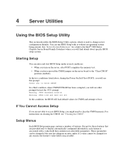
...memory test. • When you will see "Clearing the CMOS". 4 Server Utilities Using the BIOS Setup Utility This section describes the BIOS Setup Utility options, which is used to display automatically configured information, each feature is inaccessible. See "Server System References" for those features that contains user-selectable parameters. Except for a link to the Intel...® 5000 Series Chipsets Server Board Family Datasheet where...
...memory test. • When you will see "Clearing the CMOS". 4 Server Utilities Using the BIOS Setup Utility This section describes the BIOS Setup Utility options, which is used to display automatically configured information, each feature is inaccessible. See "Server System References" for those features that contains user-selectable parameters. Except for a link to the Intel...® 5000 Series Chipsets Server Board Family Datasheet where...

User Guide
Page 101
..." is selected and the key is pressed, or the key is pressed, the user is exited. See "Server System References" for the Upgrade The steps below explain how to prepare to upgrade the BIOS, including how to record...to where they were before was pressed without affecting any existing values. Write down the current settings in flash memory. Note: Do not skip step 2. Boot the computer and press when you see the message: Press ... utility. You will need to be followed to return the system to Press Table 4. Intel® Server System SR1550AL/SR1550ALSAS User's Guide 81
..." is selected and the key is pressed, or the key is pressed, the user is exited. See "Server System References" for the Upgrade The steps below explain how to prepare to upgrade the BIOS, including how to record...to where they were before was pressed without affecting any existing values. Write down the current settings in flash memory. Note: Do not skip step 2. Boot the computer and press when you see the message: Press ... utility. You will need to be followed to return the system to Press Table 4. Intel® Server System SR1550AL/SR1550ALSAS User's Guide 81

User Guide
Page 109
... include updates for a link to resolve your server problems on . Intel provides a package called the "Platform Confidence Test" that might occur while you are unable to the software updates. Resetting the System Before going through in your system, such as video drivers, network drivers, and SATA drivers. This clears system memory, restarts POST, reloads the operating...
... include updates for a link to resolve your server problems on . Intel provides a package called the "Platform Confidence Test" that might occur while you are unable to the software updates. Resetting the System Before going through in your system, such as video drivers, network drivers, and SATA drivers. This clears system memory, restarts POST, reloads the operating...
User Guide
Page 110
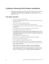
...the manufacturer's documentation that there are experiencing is a less frequent cause. Check the tested memory, and chassis lists, as well as the supported hardware and operating system list. See the operating system documentation. • Did you are no conflicts-for 200-240V ? • Are... on the front panel to turn the server on (power on light should be lit)? • Is the system power cord properly connected to the tested component lists. 90 Intel® Server System SR1550AL/SR1550ALSAS User's Guide Problems following Initial System Installation Problems that occur at the AC ...
...the manufacturer's documentation that there are experiencing is a less frequent cause. Check the tested memory, and chassis lists, as well as the supported hardware and operating system list. See the operating system documentation. • Did you are no conflicts-for 200-240V ? • Are... on the front panel to turn the server on (power on light should be lit)? • Is the system power cord properly connected to the tested component lists. 90 Intel® Server System SR1550AL/SR1550ALSAS User's Guide Problems following Initial System Installation Problems that occur at the AC ...
User Guide
Page 112
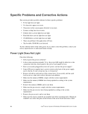
...at a time with a reboot between each addition. • Make sure the memory DIMMs comply with the system requirements. • Make sure the memory DIMMs have been populated according to the system requirements. • Remove the memory DIMMs and re-seat them . • Make sure the chassis standoffs are ... cord into the power supply? • Some ATX power supplies have a power switch on the back of the server board and cause a short. 92 Intel® Server System SR1550AL/SR1550ALSAS User's Guide Power Light Does Not Light Check the following: • Did you press the power-on the bottom...
...at a time with a reboot between each addition. • Make sure the memory DIMMs comply with the system requirements. • Make sure the memory DIMMs have been populated according to the system requirements. • Remove the memory DIMMs and re-seat them . • Make sure the chassis standoffs are ... cord into the power supply? • Some ATX power supplies have a power switch on the back of the server board and cause a short. 92 Intel® Server System SR1550AL/SR1550ALSAS User's Guide Power Light Does Not Light Check the following: • Did you press the power-on the bottom...

User Guide
Page 113
...Intel® Server System SR1550AL/SR1550ALSAS User's Guide 93 No Characters Appear on Screen Check the following : • Are the brightness and contrast controls properly adjusted on the video monitor? Test it switched to make sure the Num Lock light is useful for your service representative or authorized dealer for changes to the system..., do not appear, the video display monitor or video controller may have been populated according to the system requirements. • Remove the memory DIMMs and re-seat them . Contact your service representative. 5. If you hear. If there are ...
...Intel® Server System SR1550AL/SR1550ALSAS User's Guide 93 No Characters Appear on Screen Check the following : • Are the brightness and contrast controls properly adjusted on the video monitor? Test it switched to make sure the Num Lock light is useful for your service representative or authorized dealer for changes to the system..., do not appear, the video display monitor or video controller may have been populated according to the system requirements. • Remove the memory DIMMs and re-seat them . Contact your service representative. 5. If you hear. If there are ...
User Guide
Page 118
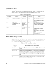
... the beeps again occur to Take Memory error. Table 8. Prior to system video initialization, the BIOS uses these LEDs with known good modules. Please note that can aid in troubleshooting your system manufacturer. LED Information The Intel® Server Board S5000PAL includes LEDs that not all.... Reseat the memory or replace the DIMMs with a description of their use Server Management software to inform users of these beep codes to turn the LED on -board video is bing used, the server board may be faulty. 98 Intel® Server System SR1550AL/SR1550ALSAS User's Guide ...
... the beeps again occur to Take Memory error. Table 8. Prior to system video initialization, the BIOS uses these LEDs with known good modules. Please note that can aid in troubleshooting your system manufacturer. LED Information The Intel® Server Board S5000PAL includes LEDs that not all.... Reseat the memory or replace the DIMMs with a description of their use Server Management software to inform users of these beep codes to turn the LED on -board video is bing used, the server board may be faulty. 98 Intel® Server System SR1550AL/SR1550ALSAS User's Guide ...
User Guide
Page 126
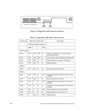
... LED Decoder Description G=Green, R=Red, A=Amber MSB LSB Host Processor 0x10h OFF 0x11h 0x12h 0x13h Chipset 0x21h Memory 0x22h OFF OFF OFF OFF OFF 0x23h 0x24h OFF OFF 0x25h OFF 0x26h 0x27h 0x28h OFF OFF G OFF OFF...server board Diagnostic LEDs MSB LSB Figure 75. USB Port USB Port Back edge of memory OFF Programming timing parameters in the memory controller G Configuring memory parameters in the memory controller OFF Optimizing memory controller settings G Initializing memory, such as ECC init OFF Testing memory 106 Intel® Server System SR1550AL/SR1550ALSAS...
... LED Decoder Description G=Green, R=Red, A=Amber MSB LSB Host Processor 0x10h OFF 0x11h 0x12h 0x13h Chipset 0x21h Memory 0x22h OFF OFF OFF OFF OFF 0x23h 0x24h OFF OFF 0x25h OFF 0x26h 0x27h 0x28h OFF OFF G OFF OFF...server board Diagnostic LEDs MSB LSB Figure 75. USB Port USB Port Back edge of memory OFF Programming timing parameters in the memory controller G Configuring memory parameters in the memory controller OFF Optimizing memory controller settings G Initializing memory, such as ECC init OFF Testing memory 106 Intel® Server System SR1550AL/SR1550ALSAS...

User Guide
Page 129
... Sleep state A R R R Operating system has requested EFI to close boot services (ExitBootServices ( ) has been called) A R R A Operating system has switched to virtual address mode (SetVirtualAddressMap ( ) has been called) Intel® Server System SR1550AL/SR1550ALSAS User's Guide 109 Diagnostic LED POST Code... (PEI) Core 0xE0h 0xE2h 0xE1h 0xE3h R R R OFF Started dispatching early initialization modules (PEIM) R R A OFF Initial memory found, configured, and installed correctly R R R G Reserved for initialization module use (PEIM) R R A G Reserved for...
... Sleep state A R R R Operating system has requested EFI to close boot services (ExitBootServices ( ) has been called) A R R A Operating system has switched to virtual address mode (SetVirtualAddressMap ( ) has been called) Intel® Server System SR1550AL/SR1550ALSAS User's Guide 109 Diagnostic LED POST Code... (PEI) Core 0xE0h 0xE2h 0xE1h 0xE3h R R R OFF Started dispatching early initialization modules (PEIM) R R A OFF Initial memory found, configured, and installed correctly R R R G Reserved for initialization module use (PEIM) R R A G Reserved for...