User Guide
Page 7
... as the fans, power supply, drives, and other components. This includes how to navigate through the BIOS Setup screens, how to perform a BIOS update, and how to add and replace components on adding and replacing components. Chapter 3 provides instructions on the server system. Use this server system. See "Server System References" on using the Intel® Server System SR1530CL / SR1530HCL / SR1530HCLS...
... as the fans, power supply, drives, and other components. This includes how to navigate through the BIOS Setup screens, how to perform a BIOS update, and how to add and replace components on adding and replacing components. Chapter 3 provides instructions on the server system. Use this server system. See "Server System References" on using the Intel® Server System SR1530CL / SR1530HCL / SR1530HCLS...
User Guide
Page 8
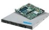
... server system • One rail kit, in the server system • Two system blowers, with the Intel® Server Board S5000VCLR. Intel® Server System Contents Your Intel® Server System SR1530CL / SR1530HCL / SR1530HCLS and/or the Intel® Server System SR1530CLR / SR1530HCLR / SR1530HCLSR ships with the following items: • One Intel® Server Board S5000VCL/S5000VCLR, installed in the server system • One 400-watt power supply module, installed in the server system...
... server system • One rail kit, in the server system • Two system blowers, with the Intel® Server Board S5000VCLR. Intel® Server System Contents Your Intel® Server System SR1530CL / SR1530HCL / SR1530HCLS and/or the Intel® Server System SR1530CLR / SR1530HCLR / SR1530HCLSR ships with the following items: • One Intel® Server Board S5000VCL/S5000VCLR, installed in the server system • One 400-watt power supply module, installed in the server system...

User Guide
Page 13
... Server Board 69 Removing the Server Board 71 Replacing the CMOS Battery 72 Replacing the Power Supply (SR1530CL/SR1530CLR 73 Replacing the Power Supply (SR1530HCL/SR1530HCLS and SR1530HCLR/ SR1530HCLSR) ...78 Replacing the Front Panel Board (SR1530CL/SR1530CLR 83 Replacing the Front Panel Board (SR1530HCL/SR1530HCLR 85 Replacing a System Blower 88 Replacing the System Blowers (SR1530CL/SR1530CLR 88 Replacing a System...
... Server Board 69 Removing the Server Board 71 Replacing the CMOS Battery 72 Replacing the Power Supply (SR1530CL/SR1530CLR 73 Replacing the Power Supply (SR1530HCL/SR1530HCLS and SR1530HCLR/ SR1530HCLSR) ...78 Replacing the Front Panel Board (SR1530CL/SR1530CLR 83 Replacing the Front Panel Board (SR1530HCL/SR1530HCLR 85 Replacing a System Blower 88 Replacing the System Blowers (SR1530CL/SR1530CLR 88 Replacing a System...
User Guide
Page 17
Setup Menu Key Use 18 Table 4. Power Supply Output Capability 102 Table 5. Other Markings ...166 Server System User Guide xvii LED Information ...114 Table 8. Product Ecology Compliance Markings 164 Table 13. NIC LED Descriptions 6 Table 3. System Status LED Color and Blink Codes 115 Table 9. Resetting the System 105 Table 7. Product Regulatory Compliance Markings 158 Table 12. POST...
Setup Menu Key Use 18 Table 4. Power Supply Output Capability 102 Table 5. Other Markings ...166 Server System User Guide xvii LED Information ...114 Table 8. Product Ecology Compliance Markings 164 Table 13. NIC LED Descriptions 6 Table 3. System Status LED Color and Blink Codes 115 Table 9. Resetting the System 105 Table 7. Product Regulatory Compliance Markings 158 Table 12. POST...
User Guide
Page 21
... 88 Figure 88. Replacing the CMOS Battery 73 Figure 73. Removing Power Supply from Server System (SR1530HCL/SR1530HCLR). 85 Figure 84. Connecting Power Cables (SR1530CL/SR1530CLR 77 Figure 77. Installing Power Supply into Server System (SR1530HCL/SR1530HCLS and SR1530HCLR/SR1530HCLSR 81 Figure 80. Installing Front Panel Board in Server System (SR1530HCL/SR1530HCLS and SR1530HCLR/SR1530HCLSR 93 Figure 93. Removing Blower Bracket...
... 88 Figure 88. Replacing the CMOS Battery 73 Figure 73. Removing Power Supply from Server System (SR1530HCL/SR1530HCLR). 85 Figure 84. Connecting Power Cables (SR1530CL/SR1530CLR 77 Figure 77. Installing Power Supply into Server System (SR1530HCL/SR1530HCLS and SR1530HCLR/SR1530HCLSR 81 Figure 80. Installing Front Panel Board in Server System (SR1530HCL/SR1530HCLS and SR1530HCLR/SR1530HCLSR 93 Figure 93. Removing Blower Bracket...
User Guide
Page 25
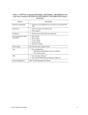
...; NIC1 Activity • NIC2 Activity • Power / Sleep • System Status • Hard Drive Activity One 400-watt power supply module • Non-redundant fans: - (SR1530CL/SR1530CLR) One PCI cooling fan - Table 1. Two system blowers • One front panel USB port • One internal USB header providing two USB ports Intel® System Management Software Server System User Guide 3
...; NIC1 Activity • NIC2 Activity • Power / Sleep • System Status • Hard Drive Activity One 400-watt power supply module • Non-redundant fans: - (SR1530CL/SR1530CLR) One PCI cooling fan - Table 1. Two system blowers • One front panel USB port • One internal USB header providing two USB ports Intel® System Management Software Server System User Guide 3

User Guide
Page 32
Rack Handles (two) B. Power Supply G. Processor Air Duct D. PCI Add-in Card Bracket E. System Memory DIMM Sockets F. Processor Sockets (two) H. Slimline Optical Drive Bay Figure 8. PCI Cooling Fan C. Internal Components D C B A K J I . System Blowers (two) I A E F G H AF001185 A. Control Panel K. Chassis Components (SR1530CL/SR1530CLR) 10 Server System User Guide Hard Drive Brackets (two) J.
Rack Handles (two) B. Power Supply G. Processor Air Duct D. PCI Add-in Card Bracket E. System Memory DIMM Sockets F. Processor Sockets (two) H. Slimline Optical Drive Bay Figure 8. PCI Cooling Fan C. Internal Components D C B A K J I . System Blowers (two) I A E F G H AF001185 A. Control Panel K. Chassis Components (SR1530CL/SR1530CLR) 10 Server System User Guide Hard Drive Brackets (two) J.

User Guide
Page 33
Processor Air Duct F. PCI Add-in Card Bracket G. Control Panel Board J. Chassis Components (SR1530HCL/SR1530HCLS and SR1530HCLR/SR1530HCLSR) Server System User Guide 11 Power Supply I A G H AF001612 A. System Blowers (2) E. Hard Disk Drives (3) Figure 9. Slimline Optical Drive Bay C. PCI Cooling Baffle D. Server Board H. Control Panel K. Rack Handles (two) B. F B A E D C K J I .
Processor Air Duct F. PCI Add-in Card Bracket G. Control Panel Board J. Chassis Components (SR1530HCL/SR1530HCLS and SR1530HCLR/SR1530HCLSR) Server System User Guide 11 Power Supply I A G H AF001612 A. System Blowers (2) E. Hard Disk Drives (3) Figure 9. Slimline Optical Drive Bay C. PCI Cooling Baffle D. Server Board H. Control Panel K. Rack Handles (two) B. F B A E D C K J I .

User Guide
Page 62
... 34. Orient the heat sink over the processor, lining up the four captive screws with the corner tabs pointed away from the power supply to provide correct airflow through the system. 2. Lower the CPU load plate. 10. Use caution when you unpack the heat sink so you do not damage the TIM. 1. Set... the bottom of it. Install the heat sinks with the four posts surrounding the processor. Gradually and equally tighten each screw is firmly tightened. 40 Server System User Guide Removing the Protective Socket Cover 9.
... 34. Orient the heat sink over the processor, lining up the four captive screws with the corner tabs pointed away from the power supply to provide correct airflow through the system. 2. Lower the CPU load plate. 10. Use caution when you unpack the heat sink so you do not damage the TIM. 1. Set... the bottom of it. Install the heat sinks with the four posts surrounding the processor. Gradually and equally tighten each screw is firmly tightened. 40 Server System User Guide Removing the Protective Socket Cover 9.

User Guide
Page 67
... Figure 39. Connecting Hard Drive Power and Data Cables (SR1530CL/ SR1530CLR) Server System User Guide 45 Connect the power cables to make sure you connect the cables between the server board and the hard drives. If a drive is closest to the power supply to the SATA 1 connector on the daisy chain power cable that is installed in Figure...
... Figure 39. Connecting Hard Drive Power and Data Cables (SR1530CL/ SR1530CLR) Server System User Guide 45 Connect the power cables to make sure you connect the cables between the server board and the hard drives. If a drive is closest to the power supply to the SATA 1 connector on the daisy chain power cable that is installed in Figure...

User Guide
Page 95
...Observe the safety and ESD precautions at the beginning of this book. Power down on page iii. 2. Remove the new lithium battery from its package, and, being careful to local ordinance. 8. Server System User Guide 73 Insert the tip of the fans that is integrated..." on the screwdriver to restore the configuration settings. For instructions, see "Removing the Server System Cover" on page iii. Remove the battery from its socket. Replacing the Power Supply (SR1530CL/ SR1530CLR) The power supply can be replaced if it fails. Figure 72. See Figure 72. 5. Dispose of...
...Observe the safety and ESD precautions at the beginning of this book. Power down on page iii. 2. Remove the new lithium battery from its package, and, being careful to local ordinance. 8. Server System User Guide 73 Insert the tip of the fans that is integrated..." on the screwdriver to restore the configuration settings. For instructions, see "Removing the Server System Cover" on page iii. Remove the battery from its socket. Replacing the Power Supply (SR1530CL/ SR1530CLR) The power supply can be replaced if it fails. Figure 72. See Figure 72. 5. Dispose of...

User Guide
Page 97
Save this screw. You will re-insert it later (see letter "B"). Remove the screw at the bottom of the chassis (see letter "A" in the following figure). Lift up slightly on the front of the server system, next to the AC power input. Removing Power Supply from the chassis. . A B C B AF000994 Figure 74. 5. Slide the power supply forward (see letter "C") and then lift it clears the foot at the back of the power supply until it from the Server System (SR1530CL/ SR1530CLR) Server System User Guide 75
Save this screw. You will re-insert it later (see letter "B"). Remove the screw at the bottom of the chassis (see letter "A" in the following figure). Lift up slightly on the front of the server system, next to the AC power input. Removing Power Supply from the chassis. . A B C B AF000994 Figure 74. 5. Slide the power supply forward (see letter "C") and then lift it clears the foot at the back of the power supply until it from the Server System (SR1530CL/ SR1530CLR) Server System User Guide 75

User Guide
Page 98
Set the front of the power supply down pushing the power supply back so it through the cut-out area at the bottom of the system (see letter "C"). C B A B AF000995 Figure 75. Installing Power Supply into the server system, sliding the power connector side in first to the server system (see letter "A" in previously to attach the power supply to fit it fits behind the foot...
Set the front of the power supply down pushing the power supply back so it through the cut-out area at the bottom of the system (see letter "C"). C B A B AF000995 Figure 75. Installing Power Supply into the server system, sliding the power connector side in first to the server system (see letter "A" in previously to attach the power supply to fit it fits behind the foot...

User Guide
Page 99
... 30. 9. A B C D AF000998 Figure 76. Install the server system cover. Server System User Guide 77 A: Aux power signal - Connect the power supply cables to : ✧ HDD1 power connector, if a hard drive is installed here. Connecting Power Cables (SR1530CL/SR1530CLR) 8. For instructions, see "Installing the Server System Cover" on cable that is closest to power supply. ✧ HDD0 power connector, if a hard drive is installed here. 7.
... 30. 9. A B C D AF000998 Figure 76. Install the server system cover. Server System User Guide 77 A: Aux power signal - Connect the power supply cables to : ✧ HDD1 power connector, if a hard drive is installed here. Connecting Power Cables (SR1530CL/SR1530CLR) 8. For instructions, see "Installing the Server System Cover" on cable that is closest to power supply. ✧ HDD0 power connector, if a hard drive is installed here. 7.

User Guide
Page 100
... all peripheral devices and the AC power cable. 3. A: Aux power signal - C: 2x4 power connector - Remove the server system cover. B: 2x12 main power connector - Power down the server and unplug all power cables connected to optical drive power, if optical drive is integrated into it fails. For instructions, see "Removing the Server System Cover". 4. To replace the power supply, use the following instructions. 1. D: Daisy-chain...
... all peripheral devices and the AC power cable. 3. A: Aux power signal - C: 2x4 power connector - Remove the server system cover. B: 2x12 main power connector - Power down the server and unplug all power cables connected to optical drive power, if optical drive is integrated into it fails. For instructions, see "Removing the Server System Cover". 4. To replace the power supply, use the following instructions. 1. D: Daisy-chain...

User Guide
Page 102
Removing Power Supply from the chassis. . Ensure that the power cable has been disconnected (see letter "B"). Slide the power supply forward (see letter "C") and then lift it clears the foot at the bottom of the power supply until it from Server System (SR1530HCL/ SR1530HCLS and SR1530HCLR/SR1530HCLSR) 80 Server System User Guide Lift up slightly on the front of the chassis (see letter "A" in the following figure). A C B AF001650 Figure 78. 6.
Removing Power Supply from the chassis. . Ensure that the power cable has been disconnected (see letter "B"). Slide the power supply forward (see letter "C") and then lift it clears the foot at the bottom of the power supply until it from Server System (SR1530HCL/ SR1530HCLS and SR1530HCLR/SR1530HCLSR) 80 Server System User Guide Lift up slightly on the front of the chassis (see letter "A" in the following figure). A C B AF001650 Figure 78. 6.

User Guide
Page 103
7. Insert the replacement power supply at the rear of the chassis (see letter "A" in first to fit it fits behind the foot at the bottom of the system (see letter "B"). Set the front of the power supply down pushing the power supply back so it through the cut-out area at an angle into Server System (SR1530HCL/ SR1530HCLS and SR1530HCLR/SR1530HCLSR) Server System User Guide 81 A B AF001651 Figure 79. Installing Power Supply into the server system, sliding the power connector side in the following figure).
7. Insert the replacement power supply at the rear of the chassis (see letter "A" in first to fit it fits behind the foot at the bottom of the system (see letter "B"). Set the front of the power supply down pushing the power supply back so it through the cut-out area at an angle into Server System (SR1530HCL/ SR1530HCLS and SR1530HCLR/SR1530HCLSR) Server System User Guide 81 A B AF001651 Figure 79. Installing Power Supply into the server system, sliding the power connector side in the following figure).

User Guide
Page 104
.... Install the processor air duct. Plug all peripheral devices and the AC power cable into the server. 82 Server System User Guide Connect the power supply cables to optical drive power, if optical drive is installed. C: 2x4 power connector - 8. A: Aux power signal - A C B E D AF001653 Figure 80. Install the server system cover. For instructions, see "Installing the Processor Air Duct" on page 33...
.... Install the processor air duct. Plug all peripheral devices and the AC power cable into the server. 82 Server System User Guide Connect the power supply cables to optical drive power, if optical drive is installed. C: 2x4 power connector - 8. A: Aux power signal - A C B E D AF001653 Figure 80. Install the server system cover. For instructions, see "Installing the Processor Air Duct" on page 33...

User Guide
Page 110
... hot-swappable. For instructions, see "Removing the Server System Cover". 4. Before removing or replacing a system blower, you must be replaced separately. If a fan in the power supply fails, the power supply must be individually replaced if one of them fails. See "Safety Information" on page 32 5. Remove the server system cover. The system blowers at the beginning of service, turn...
... hot-swappable. For instructions, see "Removing the Server System Cover". 4. Before removing or replacing a system blower, you must be replaced separately. If a fan in the power supply fails, the power supply must be individually replaced if one of them fails. See "Safety Information" on page 32 5. Remove the server system cover. The system blowers at the beginning of service, turn...

User Guide
Page 120
... drive is labeled "D". 98 Server System User Guide Left system blower G. F3: end connector to HDD0 - The end at the power supply itself is a single daisy chain cable. Aux power signal C. To make the diagram above more clear, where the connectors attach to HDD1 - Main power B. Drive power daisy cable - F1: connector closest to power supply to components, the labels...
... drive is labeled "D". 98 Server System User Guide Left system blower G. F3: end connector to HDD0 - The end at the power supply itself is a single daisy chain cable. Aux power signal C. To make the diagram above more clear, where the connectors attach to HDD1 - Main power B. Drive power daisy cable - F1: connector closest to power supply to components, the labels...
