
User Guide
Page 11
...Intel® Server System Contents viii Server System References ix Chapter 1: Server System Features 1 Chassis Component Identification 4 Front Control Panel (SR1530CL/SR1530CLR 4 Front Control Panel (SR1530HCL/SR1530HCLS and SR1530HCLR/SR1530HCLSR) 5 System Rear ...6 Peripheral Devices ...7 Internal Components 10 Configuration Jumpers ...13 RAID Support ...14 Rack-Mounted Systems ...14 Hardware Requirements ...15 Processor ...15 Memory ...15 Chapter 2: Server... the CMOS ...22 Forcing a BMC Update ...23 Chapter 3: Hardware Installations and Upgrades 25 Server System User Guide xi
...Intel® Server System Contents viii Server System References ix Chapter 1: Server System Features 1 Chassis Component Identification 4 Front Control Panel (SR1530CL/SR1530CLR 4 Front Control Panel (SR1530HCL/SR1530HCLS and SR1530HCLR/SR1530HCLSR) 5 System Rear ...6 Peripheral Devices ...7 Internal Components 10 Configuration Jumpers ...13 RAID Support ...14 Rack-Mounted Systems ...14 Hardware Requirements ...15 Processor ...15 Memory ...15 Chapter 2: Server... the CMOS ...22 Forcing a BMC Update ...23 Chapter 3: Hardware Installations and Upgrades 25 Server System User Guide xi

User Guide
Page 12
... the Front Bezel 26 Installing the Front Bezel 27 Removing and Installing the Server Cover 28 Removing the Server System Cover 28 Installing the Server System Cover 30 Removing and Installing the Processor Air Duct 32 Removing the Processor Air Duct 32 Installing the Processor Air Duct 33 Installing and Removing Memory 35 Installing DIMMs ...35 Removing DIMMs...
... the Front Bezel 26 Installing the Front Bezel 27 Removing and Installing the Server Cover 28 Removing the Server System Cover 28 Installing the Server System Cover 30 Removing and Installing the Processor Air Duct 32 Removing the Processor Air Duct 32 Installing the Processor Air Duct 33 Installing and Removing Memory 35 Installing DIMMs ...35 Removing DIMMs...
User Guide
Page 19
... Figure 19. Installing the Server System Cover (SR1530CL/SR1530CLR 31 Figure 23. Installing the Server System Cover (SR1530HCL/SR1530HCLS and SR1530HCLR/ SR1530HCLSR)...31 Figure 24. Intel® Server System SR1530HCL / SR1530HCLS and SR1530HCLR / SR1530HCLSR ...1 Figure 3. Optional Peripherals (SR1530HCL/SR1530HCLS and SR1530HCLR/SR1530HCLSR) 8 Figure 8. Removing the Server System Cover (SR1530CL/SR1530CLR 29 Figure 21. Lifting the Processor Socket Handle 38 Figure...
... Figure 19. Installing the Server System Cover (SR1530CL/SR1530CLR 31 Figure 23. Installing the Server System Cover (SR1530HCL/SR1530HCLS and SR1530HCLR/ SR1530HCLSR)...31 Figure 24. Intel® Server System SR1530HCL / SR1530HCLS and SR1530HCLR / SR1530HCLSR ...1 Figure 3. Optional Peripherals (SR1530HCL/SR1530HCLS and SR1530HCLR/SR1530HCLSR) 8 Figure 8. Removing the Server System Cover (SR1530CL/SR1530CLR 29 Figure 21. Lifting the Processor Socket Handle 38 Figure...

User Guide
Page 24
... maximum memory Intel® 5000V Chipset, consisting of the server system. Intel® Server System SR1530CL / SR1530HCL / SR1530HCLS and Intel Server System SR1530CLR / SR1530HCLR / SR1530HCLSR Feature Summary Feature Description Dimensions (SR1530CL/ SR1530CLR) Dimensions (SR1530HCL/ SR1530HCLS and SR1530HCLR/ SR1530HCLSR) Server Board Processor Memory Chipset ... control panel bezel, rack handles, and front bezel • 23 pounds One Intel® Server Board S5000VCL/S5000VCLR Support for 10/100/1000 Mb connections • Two USB 2.0 ports Internal connections: • One USB port...
... maximum memory Intel® 5000V Chipset, consisting of the server system. Intel® Server System SR1530CL / SR1530HCL / SR1530HCLS and Intel Server System SR1530CLR / SR1530HCLR / SR1530HCLSR Feature Summary Feature Description Dimensions (SR1530CL/ SR1530CLR) Dimensions (SR1530HCL/ SR1530HCLS and SR1530HCLR/ SR1530HCLSR) Server Board Processor Memory Chipset ... control panel bezel, rack handles, and front bezel • 23 pounds One Intel® Server Board S5000VCL/S5000VCLR Support for 10/100/1000 Mb connections • Two USB 2.0 ports Internal connections: • One USB port...

User Guide
Page 32
System Memory DIMM Sockets F. Slimline Optical Drive Bay Figure 8. Rack Handles (two) B. PCI Cooling Fan C. Processor Sockets (two) H. Control Panel K. Internal Components D C B A K J I . Power Supply G. System Blowers (two) I A E F G H AF001185 A. Hard Drive Brackets (two) J. Chassis Components (SR1530CL/SR1530CLR) 10 Server System User Guide PCI Add-in Card Bracket E. Processor Air Duct D.
System Memory DIMM Sockets F. Slimline Optical Drive Bay Figure 8. Rack Handles (two) B. PCI Cooling Fan C. Processor Sockets (two) H. Control Panel K. Internal Components D C B A K J I . Power Supply G. System Blowers (two) I A E F G H AF001185 A. Hard Drive Brackets (two) J. Chassis Components (SR1530CL/SR1530CLR) 10 Server System User Guide PCI Add-in Card Bracket E. Processor Air Duct D.

User Guide
Page 33
Slimline Optical Drive Bay C. PCI Add-in Card Bracket G. Control Panel Board J. Control Panel K. Server Board H. Power Supply I A G H AF001612 A. Rack Handles (two) B. Processor Air Duct F. F B A E D C K J I . Chassis Components (SR1530HCL/SR1530HCLS and SR1530HCLR/SR1530HCLSR) Server System User Guide 11 Hard Disk Drives (3) Figure 9. PCI Cooling Baffle D. System Blowers (2) E.
Slimline Optical Drive Bay C. PCI Add-in Card Bracket G. Control Panel Board J. Control Panel K. Server Board H. Power Supply I A G H AF001612 A. Rack Handles (two) B. Processor Air Duct F. F B A E D C K J I . Chassis Components (SR1530HCL/SR1530HCLS and SR1530HCLR/SR1530HCLSR) Server System User Guide 11 Hard Disk Drives (3) Figure 9. PCI Cooling Baffle D. System Blowers (2) E.

User Guide
Page 37
... a complete list of DIMM sockets A1, A2, and A3. Memory The Intel® Server System SR1530CL / SR1530HCL / SR1530HCLS and the Intel® Server System SR1530CLR / SR1530HCLR / SR1530HCLSR provide six DIMM sockets across two channels, Channel A and Channel B. Channel A consists of supported processors, see the links under "Server System References" on page ix. DIMM A3 DIMM A2 DIMM A1 DIMM...
... a complete list of DIMM sockets A1, A2, and A3. Memory The Intel® Server System SR1530CL / SR1530HCL / SR1530HCLS and the Intel® Server System SR1530CLR / SR1530HCLR / SR1530HCLSR provide six DIMM sockets across two channels, Channel A and Channel B. Channel A consists of supported processors, see the links under "Server System References" on page ix. DIMM A3 DIMM A2 DIMM A1 DIMM...
User Guide
Page 54
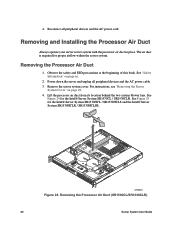
... is required for the Intel® Server System SR1530HCL / SR1530HCLS and the Intel® Server System SR1530HCLR / SR1530HCLSR. AF000973 Figure 24. Removing the Processor Air Duct 1. Removing the Processor Air Duct (SR1530CL/SR1530CLR) 32 Server System User Guide Lift the processor air duct from its location behind the two system blower fans. See Figure 24 for the Intel® Server System SR1530CL / SR1530CLR. Observe the...
... is required for the Intel® Server System SR1530HCL / SR1530HCLS and the Intel® Server System SR1530HCLR / SR1530HCLSR. AF000973 Figure 24. Removing the Processor Air Duct 1. Removing the Processor Air Duct (SR1530CL/SR1530CLR) 32 Server System User Guide Lift the processor air duct from its location behind the two system blower fans. See Figure 24 for the Intel® Server System SR1530CL / SR1530CLR. Observe the...

User Guide
Page 55
... the two system blower fans. See Figure 26 for the Intel® Server System SR1530HCL / SR1530HCLS and the Intel® Server System SR1530HCLR / SR1530HCLSR. Server System User Guide 33 AF001618 Figure 25. Observe the safety and ESD precautions at the front of the processor air duct... slots on page iii. 2. For instructions, see "Removing the Server System Cover" on page 28. 4. See Figure 27 for the Intel® Server System SR1530CL / SR1530CLR. Remove the server system cover. Removing the Processor Air Duct (SR1530HCL/SR1530HCLS and SR1530HCLR/SR1530HCLSR) Installing the...
... the two system blower fans. See Figure 26 for the Intel® Server System SR1530HCL / SR1530HCLS and the Intel® Server System SR1530HCLR / SR1530HCLSR. Server System User Guide 33 AF001618 Figure 25. Observe the safety and ESD precautions at the front of the processor air duct... slots on page iii. 2. For instructions, see "Removing the Server System Cover" on page 28. 4. See Figure 27 for the Intel® Server System SR1530CL / SR1530CLR. Remove the server system cover. Removing the Processor Air Duct (SR1530HCL/SR1530HCLS and SR1530HCLR/SR1530HCLSR) Installing the...

User Guide
Page 56
AF000974 Figure 26. Installing the Processor Air Duct (SR1530HCL/SR1530HCLS and SR1530HCLR/SR1530HCLSR) 34 Server System User Guide Installing the Processor Air Duct (SR1530CL/SR1530CLR) AF001618 Figure 27.
AF000974 Figure 26. Installing the Processor Air Duct (SR1530HCL/SR1530HCLS and SR1530HCLR/SR1530HCLSR) 34 Server System User Guide Installing the Processor Air Duct (SR1530CL/SR1530CLR) AF001618 Figure 27.

User Guide
Page 59
.... Observe the safety and ESD precautions at each end of compatible processor(s). For instructions, see "Removing the Server System Cover" on page 30. Gently spread the retaining clips at the beginning of your server. Installing the Processor To install a processor, follow these instructions: 1. Remove the server system cover. Server System User Guide 37 Keep part of this book. Installing or...
.... Observe the safety and ESD precautions at each end of compatible processor(s). For instructions, see "Removing the Server System Cover" on page 30. Gently spread the retaining clips at the beginning of your server. Installing the Processor To install a processor, follow these instructions: 1. Remove the server system cover. Server System User Guide 37 Keep part of this book. Installing or...

User Guide
Page 60
AF000650 Figure 29. Raise the CPU load plate. Raise the load plate completely. they are very sensitive and easily damaged. 38 Server System User Guide Opening the Load Plate Caution: Do not touch the socket pins; Lifting the Processor Socket Handle 5. Push the rear tab with your finger to slightly lift the front of the load plate. A B AF000651 Figure 30.
AF000650 Figure 29. Raise the CPU load plate. Raise the load plate completely. they are very sensitive and easily damaged. 38 Server System User Guide Opening the Load Plate Caution: Do not touch the socket pins; Lifting the Processor Socket Handle 5. Push the rear tab with your finger to slightly lift the front of the load plate. A B AF000651 Figure 30.

User Guide
Page 61
Removing the Shipping Cover 7. Remove the protective socket cover. Server System User Guide 39 Orient the processor with the socket so the processor cutouts match the socket notches (see letter "A" in letter B. Set the processor into place as shown in the following figure). Installing the Processor 8. Note: Make sure the alignment triangle mark and the alignment triangle...
Removing the Shipping Cover 7. Remove the protective socket cover. Server System User Guide 39 Orient the processor with the socket so the processor cutouts match the socket notches (see letter "A" in letter B. Set the processor into place as shown in the following figure). Installing the Processor 8. Note: Make sure the alignment triangle mark and the alignment triangle...

User Guide
Page 62
... Interface Material (TIM) located on page 40. Install the heat sinks with the four posts surrounding the processor. Gradually and equally tighten each screw is firmly tightened. 40 Server System User Guide Removing the Protective Socket Cover 9. For instructions, see "Installing the Heat Sink" on the bottom... of it. The fins must be positioned as shown in Figure 34. Set the heat sink over the processor as shown to avoid ...
... Interface Material (TIM) located on page 40. Install the heat sinks with the four posts surrounding the processor. Gradually and equally tighten each screw is firmly tightened. 40 Server System User Guide Removing the Protective Socket Cover 9. For instructions, see "Installing the Heat Sink" on the bottom... of it. The fins must be positioned as shown in Figure 34. Set the heat sink over the processor as shown to avoid ...

User Guide
Page 63
... unplug all peripheral devices and the AC power cable. 3. Doing so could damage the processor. 7. Server System User Guide 41 AIRFLOW 3 2 1 4 FCrohnatssis AF001049 Figure 34. Twist the heat sink slightly to reach the processor sockets. 6. For instructions, see "Removing the Server System Cover" on page 30. Observe the safety and ESD precautions at the beginning of...
... unplug all peripheral devices and the AC power cable. 3. Doing so could damage the processor. 7. Server System User Guide 41 AIRFLOW 3 2 1 4 FCrohnatssis AF001049 Figure 34. Twist the heat sink slightly to reach the processor sockets. 6. For instructions, see "Removing the Server System Cover" on page 30. Observe the safety and ESD precautions at the beginning of...

User Guide
Page 64
...HDD0. See "Safety Information" on page 28. 4. Remove the server system cover. If installing a replacement processor, see "Removing a Hard Disk Drive (SR1530CL/ SR1530CLR)" on page 46 for an Internet link to use. 42 Server System User Guide Up to be installed. Installing a Hard Disk Drive ...SR1530CLR) Note: If you are NOT hot-swappable. Power down the server. For instructions, see "Removing the Server System Cover" on page iii. 2. Otherwise, install the protective socket cover over the empty processor socket and then reinstall the chassis cover. Unplug all hard drives. ...
...HDD0. See "Safety Information" on page 28. 4. Remove the server system cover. If installing a replacement processor, see "Removing a Hard Disk Drive (SR1530CL/ SR1530CLR)" on page 46 for an Internet link to use. 42 Server System User Guide Up to be installed. Installing a Hard Disk Drive ...SR1530CLR) Note: If you are NOT hot-swappable. Power down the server. For instructions, see "Removing the Server System Cover" on page iii. 2. Otherwise, install the protective socket cover over the empty processor socket and then reinstall the chassis cover. Unplug all hard drives. ...

User Guide
Page 91
...and the AC power cable. 3. For instructions, see "Removing the Processor Air Duct" on page 32. 5. Install the processor air duct. Remove the processor air duct. Remove the server system cover. Install the PCI riser assembly into the server. See "Safety Information" on page 63. C A B AF000984...the PCI Riser Assembly" on page 33. 11. For instructions, see "Installing the Processor Air Duct" on page 64. 10. Remove the PCI riser assembly. For instructions, see "Installing the Server System Cover" on page 28. 4. Plug all peripheral devices and the AC power cable...
...and the AC power cable. 3. For instructions, see "Removing the Processor Air Duct" on page 32. 5. Install the processor air duct. Remove the processor air duct. Remove the server system cover. Install the PCI riser assembly into the server. See "Safety Information" on page 63. C A B AF000984...the PCI Riser Assembly" on page 33. 11. For instructions, see "Installing the Processor Air Duct" on page 64. 10. Remove the PCI riser assembly. For instructions, see "Installing the Server System Cover" on page 28. 4. Plug all peripheral devices and the AC power cable...

User Guide
Page 92
...9. For instructions, see "Installing DIMMs" on page 97. 11. Install the processor air duct. Install the server system cover. Plug all peripheral devices and the AC power cable into the server system, as shown by letter "A" in the following figure. 6. Connect the data ...70. Place the server board into the server. 70 Server System User Guide Attach the server board with six screws (see "Installing the Server System Cover" on page 30. 14. Installing the Server Board 7. Install the processor and the heat sink. For instructions, see "Installing the Processor" on page 37 ...
...9. For instructions, see "Installing DIMMs" on page 97. 11. Install the processor air duct. Install the server system cover. Plug all peripheral devices and the AC power cable into the server system, as shown by letter "A" in the following figure. 6. Connect the data ...70. Place the server board into the server. 70 Server System User Guide Attach the server board with six screws (see "Installing the Server System Cover" on page 30. 14. Installing the Server Board 7. Install the processor and the heat sink. For instructions, see "Installing the Processor" on page 37 ...

User Guide
Page 93
...Lift the server board from the server board. Remove the server system cover. Remove the processor air duct. Detach all peripheral devices and the AC power cable. 3. Remove the six screws from the server system (see "Removing the Server System Cover" on page 32. 5. Power down the server and ...unplug all cables connected to the server board. 7. Remove the DIMMs. For instructions, see "Removing the Processor Air Duct" on page 28. 4. For...
...Lift the server board from the server board. Remove the server system cover. Remove the processor air duct. Detach all peripheral devices and the AC power cable. 3. Remove the six screws from the server system (see "Removing the Server System Cover" on page 32. 5. Power down the server and ...unplug all cables connected to the server board. 7. Remove the DIMMs. For instructions, see "Removing the Processor Air Duct" on page 28. 4. For...

User Guide
Page 94
...processor air duct. The lithium battery on the server board powers the RTC in the absence of service, turn off the system by the equipment manufacturer. When the battery starts to the system, turn off all peripheral devices connected to weaken, it loses voltage, and the server settings stored in CMOS RAM... batteri som anbefalt av apparatfabrikanten. Hävitä käytetty paristo valmistajan ohjeiden mukaisesti. 72 Server System User Guide For instructions, see "Installing the Processor" on page 37 and "Installing the Heat Sink" on page 33. 16. Contact your customer ...
...processor air duct. The lithium battery on the server board powers the RTC in the absence of service, turn off the system by the equipment manufacturer. When the battery starts to the system, turn off all peripheral devices connected to weaken, it loses voltage, and the server settings stored in CMOS RAM... batteri som anbefalt av apparatfabrikanten. Hävitä käytetty paristo valmistajan ohjeiden mukaisesti. 72 Server System User Guide For instructions, see "Installing the Processor" on page 37 and "Installing the Heat Sink" on page 33. 16. Contact your customer ...