
User Guide
Page 14
... Bezel 26 Removing and Installing the System Cover 26 Removing the System Cover 26 Installing the System Cover 27 Removing and Installing the Processor Air Duct 28 Removing the Processor Air Duct 28 Installing the Processor Air Duct 30 Installing and Removing ...Intel® RMM NIC .. 56 Installing the Intel® RMM and Intel® RMM NIC 56 Removing the Intel® RMM and Intel® RMM NIC 57 Replacing the Backplane Board 58 Removing the Backplane Board 58 Installing the Backplane Board 59 Installing and Removing the Server Board 62 xiv Intel® Server System SR1500AL...
... Bezel 26 Removing and Installing the System Cover 26 Removing the System Cover 26 Installing the System Cover 27 Removing and Installing the Processor Air Duct 28 Removing the Processor Air Duct 28 Installing the Processor Air Duct 30 Installing and Removing ...Intel® RMM NIC .. 56 Installing the Intel® RMM and Intel® RMM NIC 56 Removing the Intel® RMM and Intel® RMM NIC 57 Replacing the Backplane Board 58 Removing the Backplane Board 58 Installing the Backplane Board 59 Installing and Removing the Server Board 62 xiv Intel® Server System SR1500AL...
User Guide
Page 19
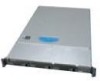
... Figure 36. Installing the PCI-X* Riser Card into the Drive Tray 43 Figure 35. Intel® Integrated Server System SR1500AL 3 Figure 2. Lifting the Processor Socket Handle 34 Figure 25. Removing Hot-swap Disk Carrier from the Server System 47 Figure 39. Removing the Slimline Optical Drive Assembly from Drive Carrier 40 Figure 32. Optional Peripherals 18 Figure...
... Figure 36. Installing the PCI-X* Riser Card into the Drive Tray 43 Figure 35. Intel® Integrated Server System SR1500AL 3 Figure 2. Lifting the Processor Socket Handle 34 Figure 25. Removing Hot-swap Disk Carrier from the Server System 47 Figure 39. Removing the Slimline Optical Drive Assembly from Drive Carrier 40 Figure 32. Optional Peripherals 18 Figure...
User Guide
Page 26
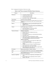
Table 2. Intel® Server System SR1500AL Feature Summary Feature Dimensions Server Board Processor Memory Chipset Peripheral Interfaces I /O Controller Hub External connections: • Stacked PS/2* ports for keyboard and mouse • RJ45 Serial B port • Two RJ45 NIC connectors for 10/100/1000 Mb connections &#... 1U PCI-X* and PCI Express* riser cards 4 Intel® Server System SR1500AL User's Guide max chassis weight Intel® Server Board S5000PAL Support for up to two Dual-Core Intel® Xeon® processors 5000 sequence • Eight DIMM slots supporting stacked ...
Table 2. Intel® Server System SR1500AL Feature Summary Feature Dimensions Server Board Processor Memory Chipset Peripheral Interfaces I /O Controller Hub External connections: • Stacked PS/2* ports for keyboard and mouse • RJ45 Serial B port • Two RJ45 NIC connectors for 10/100/1000 Mb connections &#... 1U PCI-X* and PCI Express* riser cards 4 Intel® Server System SR1500AL User's Guide max chassis weight Intel® Server Board S5000PAL Support for up to two Dual-Core Intel® Xeon® processors 5000 sequence • Eight DIMM slots supporting stacked ...

User Guide
Page 27
...8226; One internal USB header providing two USB ports Intel® System Management Software Intel® Server System SR1500AL User's Guide 5 Table 2. Intel® Server System SR1500AL Feature Summary Feature Hard Drive Controller Options Peripherals Control ...System Management With Intel® Local Control Panel: • NIC1 Activity • NIC2 Activity • Power / Sleep • System Status • System Identification • Hard Drive Activity • LCD Display Single 600 W power supply module • Six 4-pin fan headers supporting two processor fans, and four system...
...8226; One internal USB header providing two USB ports Intel® System Management Software Intel® Server System SR1500AL User's Guide 5 Table 2. Intel® Server System SR1500AL Feature Summary Feature Hard Drive Controller Options Peripherals Control ...System Management With Intel® Local Control Panel: • NIC1 Activity • NIC2 Activity • Power / Sleep • System Status • System Identification • Hard Drive Activity • LCD Display Single 600 W power supply module • Six 4-pin fan headers supporting two processor fans, and four system...

User Guide
Page 28
Server board G. Processor air duct K. Hard drive bays (drives not included) O. ChassisComponents 6 Intel® Server System SR1500AL User's Guide Control panel (standard control panel shown) N. If you are near the system, you identify the components of the chassis cover to assist in riser assembly ...Chassis Component Identification This section helps you can also use the Quick Reference Label provided on the inside of your server system. Bridge board M. Backplane C. PCI card bracket (low profile) J. Slimline Optical Drive Bay (drive not included) P. ...
Server board G. Processor air duct K. Hard drive bays (drives not included) O. ChassisComponents 6 Intel® Server System SR1500AL User's Guide Control panel (standard control panel shown) N. If you are near the system, you identify the components of the chassis cover to assist in riser assembly ...Chassis Component Identification This section helps you can also use the Quick Reference Label provided on the inside of your server system. Bridge board M. Backplane C. PCI card bracket (low profile) J. Slimline Optical Drive Bay (drive not included) P. ...

User Guide
Page 50
... server board user guide for proper airflow within the server system. The air duct is required for instructions on adding or replacing a processor, first remove the processor air duct, and then see "Removing the System Cover". 4. Removing the Processor Air Duct 1. B A TP02196 Figure 19. Lift the processor air duct from its location over the two processor sockets. 28 Intel® Server System SR1500AL...
... server board user guide for proper airflow within the server system. The air duct is required for instructions on adding or replacing a processor, first remove the processor air duct, and then see "Removing the System Cover". 4. Removing the Processor Air Duct 1. B A TP02196 Figure 19. Lift the processor air duct from its location over the two processor sockets. 28 Intel® Server System SR1500AL...

User Guide
Page 51
TP02201 Figure 20. Removing the Processor Air Duct Intel® Server System SR1500AL User's Guide 29
TP02201 Figure 20. Removing the Processor Air Duct Intel® Server System SR1500AL User's Guide 29

User Guide
Page 52
... unplug all peripheral devices and the AC power cable(s) into the server. 30 Intel® Server System SR1500AL User's Guide only if two processors are installed: remove air dam (see letter "A"). 5. Place the processor air duct over to pinch or disengage cables that may be near or under the air duct. 7....power cable(s). 3. The front edge of this book. Notes: Do not remove the air dam if only one processor is installed. Install the server system cover. Installing the Processor Air Duct 1. Observe the safety and ESD precautions at the beginning of the air duct should contact the fan...
... unplug all peripheral devices and the AC power cable(s) into the server. 30 Intel® Server System SR1500AL User's Guide only if two processors are installed: remove air dam (see letter "A"). 5. Place the processor air duct over to pinch or disengage cables that may be near or under the air duct. 7....power cable(s). 3. The front edge of this book. Notes: Do not remove the air dam if only one processor is installed. Install the server system cover. Installing the Processor Air Duct 1. Observe the safety and ESD precautions at the beginning of the air duct should contact the fan...

User Guide
Page 53
...DIMM A2, DIMM B1, DIMM B2, DIMM C1, DIMM C2, DIMM D1 and DIMM D2 starting from the server. 4. Turn off all peripheral devices connected to the list of the memory requirements and options. Disconnect the AC power...Processor Air Duct Installing and Removing Memory The silkscreen on the board for a discussion of tested DIMMs. Installing DIMMs To install DIMMs, follow these steps: 1. Turn off the server. 3. See "Server System References" for a link to the server. Observe the safety and ESD precautions in "Safety Information". 2. TP02202 Figure 22. Intel® Server System SR1500AL...
...DIMM A2, DIMM B1, DIMM B2, DIMM C1, DIMM C2, DIMM D1 and DIMM D2 starting from the server. 4. Turn off all peripheral devices connected to the list of the memory requirements and options. Disconnect the AC power...Processor Air Duct Installing and Removing Memory The silkscreen on the board for a discussion of tested DIMMs. Installing DIMMs To install DIMMs, follow these steps: 1. Turn off the server. 3. See "Server System References" for a link to the server. Observe the safety and ESD precautions in "Safety Information". 2. TP02202 Figure 22. Intel® Server System SR1500AL...

User Guide
Page 55
... the metal chassis before touching the processor or server board. See "Server System References" for proper cooling of the socket. Intel® Server System SR1500AL User's Guide 33 Installing or Replacing the Processor Caution: Processor must be removed for a link to the server. Turn off the server. 3. 11. Reinstall and reconnect any parts you install a processor that came with the metal chassis to...
... the metal chassis before touching the processor or server board. See "Server System References" for proper cooling of the socket. Intel® Server System SR1500AL User's Guide 33 Installing or Replacing the Processor Caution: Processor must be removed for a link to the server. Turn off the server. 3. 11. Reinstall and reconnect any parts you install a processor that came with the metal chassis to...

User Guide
Page 56
... easily damaged. 9. For instructions, see Figure 25). Lifting the Processor Socket Handle 8. Note: Make sure the alignment triangle mark and the alignment triangle cutout align correctly. 34 Intel® Server System SR1500AL User's Guide Locate the processor socket and raise the socket handle completely (see "Removing the System Cover". 5. A B TP02075 Figure 25. Remove the heat sink, if...
... easily damaged. 9. For instructions, see Figure 25). Lifting the Processor Socket Handle 8. Note: Make sure the alignment triangle mark and the alignment triangle cutout align correctly. 34 Intel® Server System SR1500AL User's Guide Locate the processor socket and raise the socket handle completely (see "Removing the System Cover". 5. A B TP02075 Figure 25. Remove the heat sink, if...

User Guide
Page 57
Set the heat sink over the processor, lining up the four captive screws with the four posts surrounding the processor. 2. Intel® Server System SR1500AL User's Guide 35 10. A B TP02076 Figure 26. Removing the Socket Cover 11. Gradually and equally tighten ...each captive screw until each is firmly tightened. Note: Retain the protective socket cover for use when removing a processor that will not ...
Set the heat sink over the processor, lining up the four captive screws with the four posts surrounding the processor. 2. Intel® Server System SR1500AL User's Guide 35 10. A B TP02076 Figure 26. Removing the Socket Cover 11. Gradually and equally tighten ...each captive screw until each is firmly tightened. Note: Retain the protective socket cover for use when removing a processor that will not ...

User Guide
Page 58
... the AC power cord(s) from the processor. Lift the heat sink from the processor. Doing so could damage the processor. 8. Replace the system's cover and reconnect the AC power cord(s). Remove the server's cover. Twist the heat sink slightly to reach the processor sockets. 5. Lift the processor lever. 36 Intel® Server System SR1500AL User's Guide Reinstall and reconnect any parts...
... the AC power cord(s) from the processor. Lift the heat sink from the processor. Doing so could damage the processor. 8. Replace the system's cover and reconnect the AC power cord(s). Remove the server's cover. Twist the heat sink slightly to reach the processor sockets. 5. Lift the processor lever. 36 Intel® Server System SR1500AL User's Guide Reinstall and reconnect any parts...

User Guide
Page 59
... installation processes will require that you remove the small air baffle that is required for a component installation process. Intel® Server System SR1500AL User's Guide 37 Always operate your server. Remove the processor. 11. If installing a replacement processor, see "Installing the Processor". The small air baffle is placed behind the hard drive bays, near the front of your...
... installation processes will require that you remove the small air baffle that is required for a component installation process. Intel® Server System SR1500AL User's Guide 37 Always operate your server. Remove the processor. 11. If installing a replacement processor, see "Installing the Processor". The small air baffle is placed behind the hard drive bays, near the front of your...

User Guide
Page 69
... unplug all peripheral devices and the AC power cable(s). 3. Removing PCI Riser Assembly from the Server System Intel® Server System SR1500AL User's Guide 47 For instructions, see letter "B"). Remove the processor air duct by lifting straight up (see "Removing the System Cover". 4. A A B AF000358 Figure 38. Lift riser assembly straight up . 5. Installing and Removing the PCI Riser Assembly...
... unplug all peripheral devices and the AC power cable(s). 3. Removing PCI Riser Assembly from the Server System Intel® Server System SR1500AL User's Guide 47 For instructions, see letter "B"). Remove the processor air duct by lifting straight up (see "Removing the System Cover". 4. A A B AF000358 Figure 38. Lift riser assembly straight up . 5. Installing and Removing the PCI Riser Assembly...

User Guide
Page 70
...clip as shown in cards that procedure. For instructions, see "Installing the Front Bezel". 9. 8. Installing PCI Riser Assembly into the server. 48 Intel® Server System SR1500AL User's Guide See your add-in Card". 9. If you need to add-in the figure (see letter "A"). 2. Connect any cables...back of the PCI riser assembly engage the server system back panel slots. Re-install the processor air duct. For instructions, see "Installing the Processor Air Duct". 7. Plug all peripheral devices and the AC power cable(s) into the Server System 3. If you removed the PCI riser ...
...clip as shown in cards that procedure. For instructions, see "Installing the Front Bezel". 9. 8. Installing PCI Riser Assembly into the server. 48 Intel® Server System SR1500AL User's Guide See your add-in Card". 9. If you need to add-in the figure (see letter "A"). 2. Connect any cables...back of the PCI riser assembly engage the server system back panel slots. Re-install the processor air duct. For instructions, see "Installing the Processor Air Duct". 7. Plug all peripheral devices and the AC power cable(s) into the Server System 3. If you removed the PCI riser ...

User Guide
Page 71
... the power button, and unplug the AC power cord from the PCI riser connector. For instructions, see "Removing the Processor Air Duct". 5. Intel® Server System SR1500AL User's Guide 49 While holding the lever back, push firmly on the wrong side of the riser module, to disengage... the connector from the riser pins (see letter "B" in the figure below) and remove from the server system (see letter "A" in Card". 8. Before ...
... the power button, and unplug the AC power cord from the PCI riser connector. For instructions, see "Removing the Processor Air Duct". 5. Intel® Server System SR1500AL User's Guide 49 While holding the lever back, push firmly on the wrong side of the riser module, to disengage... the connector from the riser pins (see letter "B" in the figure below) and remove from the server system (see letter "A" in Card". 8. Before ...

User Guide
Page 72
... cables to add-in card requirements. 14. Plug all peripheral devices and the AC power cable(s) into the server. 50 Intel® Server System SR1500AL User's Guide For instructions, see "Installing the System Cover". 16. Re-install the processor air duct. For instructions, see "Installing a PCI Addin Card". 12. See your add-in card documentation for information...
... cables to add-in card requirements. 14. Plug all peripheral devices and the AC power cable(s) into the server. 50 Intel® Server System SR1500AL User's Guide For instructions, see "Installing the System Cover". 16. Re-install the processor air duct. For instructions, see "Installing a PCI Addin Card". 12. See your add-in card documentation for information...

User Guide
Page 73
... and the AC power cable(s). 3. For instructions, see "Removing the Processor Air Duct". 5. For instructions, see "Removing a PCI Add-in Card". 13. Installing the PCI-X* Riser Card into the server system. in Card". 8. Install the PCI riser assembly into the Server System 11. Intel® Server System SR1500AL User's Guide 51 Remove any add-in card(s) if desired. Install...
... and the AC power cable(s). 3. For instructions, see "Removing the Processor Air Duct". 5. For instructions, see "Removing a PCI Add-in Card". 13. Installing the PCI-X* Riser Card into the server system. in Card". 8. Install the PCI riser assembly into the Server System 11. Intel® Server System SR1500AL User's Guide 51 Remove any add-in card(s) if desired. Install...

User Guide
Page 74
... Intel® Server System SR1500AL User's Guide Open the rear retention clip by pushing the blue slide upward and rotating clip to install and remove a PCI add-in Card The instructions below describe how to the fully open position (see letter "A"). 7. B A C AF000361 Figure 42. Installing and Removing a PCI Add-in card. Remove the processor air...
... Intel® Server System SR1500AL User's Guide Open the rear retention clip by pushing the blue slide upward and rotating clip to install and remove a PCI add-in Card The instructions below describe how to the fully open position (see letter "A"). 7. B A C AF000361 Figure 42. Installing and Removing a PCI Add-in card. Remove the processor air...