
User Guide
Page 1
Intel® Server Board SE7320SP2 / SE7525GP2 User Guide A Guide for Technically Qualified Assemblers of Intel® Identified Subassemblies/Products Order Number: C62033-002
Intel® Server Board SE7320SP2 / SE7525GP2 User Guide A Guide for Technically Qualified Assemblers of Intel® Identified Subassemblies/Products Order Number: C62033-002
User Guide
Page 3
... may be used with your server: Processors, memory DIMMs, hard drive, floppy drive, CD-ROM or DVD-ROM drive, RAID controller, operating system. Intel Server Board SE7320SP2 / SE7525GP2 User Guide iii Preface About this Manual Thank you for purchasing and using the utilities that are compatible with the following accessory items for your board...
... may be used with your server: Processors, memory DIMMs, hard drive, floppy drive, CD-ROM or DVD-ROM drive, RAID controller, operating system. Intel Server Board SE7320SP2 / SE7525GP2 User Guide iii Preface About this Manual Thank you for purchasing and using the utilities that are compatible with the following accessory items for your board...

User Guide
Page 4
...and interactive repair information Use this Document or Software Technical Product Specification Intel® Server Board SE7320SP2 Quick Start User's Guide in the product box Intel® Server Board SE7525GP2 Quick Start User's Guide in the product box A link to the SMaRT Tool is available... List Supported Processors Supported Memory Power Budget Intel Server Management Driver (for operating system drivers) For firmware and BIOS updates Firmware Update For diagnostics test software Diagnostics Intel Server Board SE7320SP2 / SE7525GP2 User Guide iv For this information or software For ...
...and interactive repair information Use this Document or Software Technical Product Specification Intel® Server Board SE7320SP2 Quick Start User's Guide in the product box Intel® Server Board SE7525GP2 Quick Start User's Guide in the product box A link to the SMaRT Tool is available... List Supported Processors Supported Memory Power Budget Intel Server Management Driver (for operating system drivers) For firmware and BIOS updates Firmware Update For diagnostics test software Diagnostics Intel Server Board SE7320SP2 / SE7525GP2 User Guide iv For this information or software For ...

User Guide
Page 5
...AC power. Intended Uses This product was evaluated as the microprocessor used on this guide to ensure and maintain compliance with your local Intel Representative. Intel Server Board SE7320SP2 / SE7525GP2 User Guide v Use of other products / components will void the UL listing and other regulatory... or equipment damage can result. Preface Safety Information WARNING Before working with existing product certifications and approvals. Integration of this guide or any components. Warnings System power on power, telephone, and communication cables. You must unplug the AC power cord from...
...AC power. Intended Uses This product was evaluated as the microprocessor used on this guide to ensure and maintain compliance with your local Intel Representative. Intel Server Board SE7320SP2 / SE7525GP2 User Guide v Use of other products / components will void the UL listing and other regulatory... or equipment damage can result. Preface Safety Information WARNING Before working with existing product certifications and approvals. Integration of this guide or any components. Warnings System power on power, telephone, and communication cables. You must unplug the AC power cord from...

User Guide
Page 6
...If your jumpers do not have a small tab on top that you perform all procedures in this chapter only at http://support.intel.com/support/motherboards/server/safecert.htm. when handling components. 6. Contact should be sharp pins and edges on some electrostatic discharge (ESD... some board and chassis parts. A microprocessor and heat sink may be made with the pliers, never the wide sides. Intel Server Board SE7320SP2 / SE7525GP2 User Guide vi Do not slide board over two jumper pins. Safety Cautions Read all peripheral devices connected to the system. 2. Turn...
...If your jumpers do not have a small tab on top that you perform all procedures in this chapter only at http://support.intel.com/support/motherboards/server/safecert.htm. when handling components. 6. Contact should be sharp pins and edges on some electrostatic discharge (ESD... some board and chassis parts. A microprocessor and heat sink may be made with the pliers, never the wide sides. Intel Server Board SE7320SP2 / SE7525GP2 User Guide vi Do not slide board over two jumper pins. Safety Cautions Read all peripheral devices connected to the system. 2. Turn...

User Guide
Page 11
... Drive Activity Light Does Not Light 42 CD-ROM Drive or DVD-ROM Drive Activity Light Does Not Light 42 Cannot Connect to a Server 42 Intel Server Board SE7320SP2 / SE7525GP2 User Guide 11
... Drive Activity Light Does Not Light 42 CD-ROM Drive or DVD-ROM Drive Activity Light Does Not Light 42 Cannot Connect to a Server 42 Intel Server Board SE7320SP2 / SE7525GP2 User Guide 11

User Guide
Page 12
... 54 Europe (CE Declaration of Conformity 54 Taiwan Declaration of Conformity (BSMI 54 Korean Compliance (RRL 54 Getting Help ...55 Intel® Server Issue Report Form 57 Intel Server Board SE7320SP2 / SE7525GP2 User Guide 12 Problems with Network 43 System Boots when Installing PCI Card 43 Problems with Newly Installed Application Software 44 Problems with...
... 54 Europe (CE Declaration of Conformity 54 Taiwan Declaration of Conformity (BSMI 54 Korean Compliance (RRL 54 Getting Help ...55 Intel® Server Issue Report Form 57 Intel Server Board SE7320SP2 / SE7525GP2 User Guide 12 Problems with Network 43 System Boots when Installing PCI Card 43 Problems with Newly Installed Application Software 44 Problems with...

User Guide
Page 13
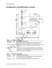
...27 Figure 9. Table 3. Table 7. Table 2. Table 4. Table 8. Intel Server Board SE7320SP2 / SE7525GP2 Layout 18 Figure 3. Contents Figures Figure 1. Intel® Server Board SE7320SP2 15 Figure 2. Table 6. Server Board SE7320SP2 Features 16 Server Board SE7525GP2 Features 17 Configuration Jumper [J17 19 BIOS Select...Messages 47 Beep Codes 48 BIOS Recovery Beep Codes 49 Product Certification Markings 52 Intel Server Board SE7320SP2 / SE7525GP2 User Guide 13 Replacing the Battery 30 Tables Table 1. Table 5. Table 10. Configuration and BIOS Select Jumper Locations...
...27 Figure 9. Table 3. Table 7. Table 2. Table 4. Table 8. Intel Server Board SE7320SP2 / SE7525GP2 Layout 18 Figure 3. Contents Figures Figure 1. Intel® Server Board SE7320SP2 15 Figure 2. Table 6. Server Board SE7320SP2 Features 16 Server Board SE7525GP2 Features 17 Configuration Jumper [J17 19 BIOS Select...Messages 47 Beep Codes 48 BIOS Recovery Beep Codes 49 Product Certification Markings 52 Intel Server Board SE7320SP2 / SE7525GP2 User Guide 13 Replacing the Battery 30 Tables Table 1. Table 5. Table 10. Configuration and BIOS Select Jumper Locations...

User Guide
Page 15
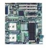
... This chapter provides a photograph of the product, a list of server board features, and diagrams showing the location of server board SE7320SP2 provides an additional PCI-Express device for Serial ATA drives. ƒ The LX version of important components and connections on the server ... Serial ATA and dual- The Server Board SE7320SP2 is provided for 10/100/1000 Mbits/sec Ethernet LAN connectivity and a 4-port Silicon Image* Serial ATA controller: SI3124. Intel® Server Board SE7320SP2 Intel Server Board SE7320SP2 / SE7525GP2 User Guide 15 channel Parallel ATA support. 1 Server ...
... This chapter provides a photograph of the product, a list of server board features, and diagrams showing the location of server board SE7320SP2 provides an additional PCI-Express device for Serial ATA drives. ƒ The LX version of important components and connections on the server ... Serial ATA and dual- The Server Board SE7320SP2 is provided for 10/100/1000 Mbits/sec Ethernet LAN connectivity and a 4-port Silicon Image* Serial ATA controller: SI3124. Intel® Server Board SE7320SP2 Intel Server Board SE7320SP2 / SE7525GP2 User Guide 15 channel Parallel ATA support. 1 Server ...

User Guide
Page 16
... SE7320SP2 / SE7525GP2 User Guide 16 one x4 PCI-Express; Server Board SE7320SP2 Features Feature Description Processors Memory Chipset Support for two Intel® Xeon™ processors in two 604-pin Intel Xeon processor sockets with an 800 MHz system bus ƒ Four 184-pin DDR SDRAM Dual Inline Memory Module (DIMM) sockets ƒ Support for up to 8 GB Registered ECC...
... SE7320SP2 / SE7525GP2 User Guide 16 one x4 PCI-Express; Server Board SE7320SP2 Features Feature Description Processors Memory Chipset Support for two Intel® Xeon™ processors in two 604-pin Intel Xeon processor sockets with an 800 MHz system bus ƒ Four 184-pin DDR SDRAM Dual Inline Memory Module (DIMM) sockets ƒ Support for up to 8 GB Registered ECC...

User Guide
Page 17
...604-pin Intel Xeon processor sockets with an 800 MHz system bus ƒ Four 184-pin DDR SDRAM Dual Inline Memory Module (DIMM) sockets ƒ Support for up to 8 GB Registered ECC system memory ƒ Support for single-sided or double-sided DIMMs (DDR266/333) Intel® E7525... ƒ Two external USB 2.0 ports on some FRU devices (Processors, Power) ƒ Port-80 Diagnostic LEDs displaying POST Codes Intel Server Board SE7320SP2 / SE7525GP2 User Guide 17 Server Board Features Table 2 summarizes the major features of the chassis (four total possible USB 2.0 ports) ƒ One serial...
...604-pin Intel Xeon processor sockets with an 800 MHz system bus ƒ Four 184-pin DDR SDRAM Dual Inline Memory Module (DIMM) sockets ƒ Support for up to 8 GB Registered ECC system memory ƒ Support for single-sided or double-sided DIMMs (DDR266/333) Intel® E7525... ƒ Two external USB 2.0 ports on some FRU devices (Processors, Power) ƒ Port-80 Diagnostic LEDs displaying POST Codes Intel Server Board SE7320SP2 / SE7525GP2 User Guide 17 Server Board Features Table 2 summarizes the major features of the chassis (four total possible USB 2.0 ports) ƒ One serial...

User Guide
Page 18
... 6 KK: Chassis Intrusion Header R: System Fan Header 5 LL: Serial B Header S: Processor 2 Fan Header MM: SCSI LED Connector T: ATA Power Connector Figure 2. Intel Server Board SE7320SP2 / SE7525GP2 Layout Intel Server Board SE7320SP2 / SE7525GP2 User Guide 18 AB CD E G F MM LL KK JJ II H I : Auxiliary Power Connector CC: Front Panel Connector J: System Fan Header 1 DD: SATA Backplane Header...
... 6 KK: Chassis Intrusion Header R: System Fan Header 5 LL: Serial B Header S: Processor 2 Fan Header MM: SCSI LED Connector T: ATA Power Connector Figure 2. Intel Server Board SE7320SP2 / SE7525GP2 Layout Intel Server Board SE7320SP2 / SE7525GP2 User Guide 18 AB CD E G F MM LL KK JJ II H I : Auxiliary Power Connector CC: Front Panel Connector J: System Fan Header 1 DD: SATA Backplane Header...
User Guide
Page 19
These pins should be jumpered on 9-10 for normal operation. Password Clear 6-7 If these pins are jumpered, administrator and user passwords will be jumpered on 1-2 for normal operation. These pins should be cleared on which is typically only used when the BIOS has become corrupted. ..., the board will attempt to recover the BIOS by loading the BIOS code into the flash device from a floppy disk. This jumper is available first. Intel Server Board SE7320SP2 / SE7525GP2 User Guide 19
These pins should be jumpered on 9-10 for normal operation. Password Clear 6-7 If these pins are jumpered, administrator and user passwords will be jumpered on 1-2 for normal operation. These pins should be cleared on which is typically only used when the BIOS has become corrupted. ..., the board will attempt to recover the BIOS by loading the BIOS code into the flash device from a floppy disk. This jumper is available first. Intel Server Board SE7320SP2 / SE7525GP2 User Guide 19

User Guide
Page 20
... 2 (1Gbit. Back Panel Connectors The NIC LEDs at the right and left LED is on or blinking) 100 Mbps connection 1000 Mbps connection Intel Server Board SE7320SP2 / SE7525GP2 User Guide 20 SE7320SP2 LX server board only) H. NIC LEDs NIC NIC1 / NIC2 (Gigabit) LED Color Left LED Right LED LED State Off Solid Amber Blinking Amber...
... 2 (1Gbit. Back Panel Connectors The NIC LEDs at the right and left LED is on or blinking) 100 Mbps connection 1000 Mbps connection Intel Server Board SE7320SP2 / SE7525GP2 User Guide 20 SE7320SP2 LX server board only) H. NIC LEDs NIC NIC1 / NIC2 (Gigabit) LED Color Left LED Right LED LED State Off Solid Amber Blinking Amber...

User Guide
Page 21
... system fans. ATA Connectors F. +12V CPU Power Connector P. B C A D T S R Serial ATA E 12V F Q P O I D E N K M LJ CPU 2 Socket H I . OEM RMC Connector H. Making Connections to the Server Board Intel Server Board SE7320SP2 / SE7525GP2 User Guide 21 This is necessary because the hard drive cage contains one of the connections shown in Figure 5. IPMB Connector TP00683 B. Floppy Drive Connector C. Processor...
... system fans. ATA Connectors F. +12V CPU Power Connector P. B C A D T S R Serial ATA E 12V F Q P O I D E N K M LJ CPU 2 Socket H I . OEM RMC Connector H. Making Connections to the Server Board Intel Server Board SE7320SP2 / SE7525GP2 User Guide 21 This is necessary because the hard drive cage contains one of the connections shown in Figure 5. IPMB Connector TP00683 B. Floppy Drive Connector C. Processor...
User Guide
Page 22
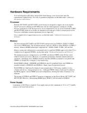
... links under "Additional Information and Software." Power Supply A minimum of DDR266 and DDR333 memory is required. Intel Server Board SE7320SP2 / SE7525GP2 User Guide 22 Hardware Requirements To avoid integration difficulties and possible board damage, your system must be populated in two ...DIMM banks. Both server boards are designed to be treated as DDR266. The minimum memory configuration is one or two Intel® Xeon...
... links under "Additional Information and Software." Power Supply A minimum of DDR266 and DDR333 memory is required. Intel Server Board SE7320SP2 / SE7525GP2 User Guide 22 Hardware Requirements To avoid integration difficulties and possible board damage, your system must be populated in two ...DIMM banks. Both server boards are designed to be treated as DDR266. The minimum memory configuration is one or two Intel® Xeon...

User Guide
Page 23
... off all peripheral devices connected to the processor socket. Disconnect the AC power cord. 4. DIMM2A is the socket closest to the server. See Figure 6. Intel Server Board SE7320SP2 / SE7525GP2 User Guide 23 For DIMM population rules, see "Memory." See "Safety Information." 2. 2 Server Board Installations and Upgrades Before You Begin Before working with your chassis...
... off all peripheral devices connected to the processor socket. Disconnect the AC power cord. 4. DIMM2A is the socket closest to the server. See Figure 6. Intel Server Board SE7320SP2 / SE7525GP2 User Guide 23 For DIMM population rules, see "Memory." See "Safety Information." 2. 2 Server Board Installations and Upgrades Before You Begin Before working with your chassis...

User Guide
Page 24
... anti-static package. 8. Make sure the clips are pushed outward to the open position. 7. Reconnect any internal components you needed to disconnect. 13. Intel Server Board SE7320SP2 / SE7525GP2 User Guide 24 Reconnect or replace any external components you needed to disconnect or remove. 12. Insert the bottom edge of the DIMM with the keys...
... anti-static package. 8. Make sure the clips are pushed outward to the open position. 7. Reconnect any internal components you needed to disconnect. 13. Intel Server Board SE7320SP2 / SE7525GP2 User Guide 24 Reconnect or replace any external components you needed to disconnect or remove. 12. Insert the bottom edge of the DIMM with the keys...

User Guide
Page 25
... or replace any external components you needed to the server. This socket is located closest to install or replace a processor instead of compatible processors. Intel Server Board SE7320SP2 / SE7525GP2 User Guide 25 Observe the safety and ESD precautions at each end of your chassis documentation for a link to disconnect or remove. 8. Hold the DIMM...
... or replace any external components you needed to the server. This socket is located closest to install or replace a processor instead of compatible processors. Intel Server Board SE7320SP2 / SE7525GP2 User Guide 25 Observe the safety and ESD precautions at each end of your chassis documentation for a link to disconnect or remove. 8. Hold the DIMM...

User Guide
Page 26
Remove the chassis cover. A B OM15042 Figure 7. Opening Socket Lever and Attaching Processor Intel Server Board SE7320SP2 / SE7525GP2 User Guide 26 Installing the Processor 1. Align the pins of this book. See your system by unplugging the AC power cord. 4. Lift the socket lever for instructions. 5. ...
Remove the chassis cover. A B OM15042 Figure 7. Opening Socket Lever and Attaching Processor Intel Server Board SE7320SP2 / SE7525GP2 User Guide 26 Installing the Processor 1. Align the pins of this book. See your system by unplugging the AC power cord. 4. Lift the socket lever for instructions. 5. ...

