
User Guide
Page 1
Intel® Server Board SE7320SP2 / SE7525GP2 User Guide A Guide for Technically Qualified Assemblers of Intel® Identified Subassemblies/Products Order Number: C62033-002
Intel® Server Board SE7320SP2 / SE7525GP2 User Guide A Guide for Technically Qualified Assemblers of Intel® Identified Subassemblies/Products Order Number: C62033-002
User Guide
Page 3
...drive, CD-ROM or DVD-ROM drive, RAID controller, operating system. Chapter 2 provides instructions on the Intel Server Board SE7320SP2 / SE7525GP2. This manual is available in the Technical Product Specification. Information about which accessories, memory, processors, and...for ordering information for performing troubleshooting activities to http://www.support.intel.com/support/motherboards/server/se7320SP2/ or http://www.support.intel.com/support/motherboards/server/se7525GP2/. Intel Server Board SE7320SP2 / SE7525GP2 User Guide iii This document provides a brief overview of ...
...drive, CD-ROM or DVD-ROM drive, RAID controller, operating system. Chapter 2 provides instructions on the Intel Server Board SE7320SP2 / SE7525GP2. This manual is available in the Technical Product Specification. Information about which accessories, memory, processors, and...for ordering information for performing troubleshooting activities to http://www.support.intel.com/support/motherboards/server/se7320SP2/ or http://www.support.intel.com/support/motherboards/server/se7525GP2/. Intel Server Board SE7320SP2 / SE7525GP2 User Guide iii This document provides a brief overview of ...

User Guide
Page 4
... left side of drivers available) Operating System Driver (for operating system drivers) For firmware and BIOS updates Firmware Update For diagnostics test software Diagnostics Intel Server Board SE7320SP2 / SE7525GP2 User Guide iv Additional Information and Software If you just received this product and need more information about this product or information about this...
... left side of drivers available) Operating System Driver (for operating system drivers) For firmware and BIOS updates Firmware Update For diagnostics test software Diagnostics Intel Server Board SE7320SP2 / SE7525GP2 User Guide iv Additional Information and Software If you just received this product and need more information about this product or information about this...

User Guide
Page 5
... Testing Before computer integration, make sure that the chassis, power supply, and other modules have passed EMC testing using this guide or any components. Intel Server Board SE7320SP2 / SE7525GP2 User Guide v See "Regulatory and Integration Information" for other product categories and environments (such as: medical, industrial, telecommunications, NEBS, residential, alarm systems, ... as a reference, pay close attention to ensure and maintain compliance with existing product certifications and approvals. For more information please contact your local Intel Representative.
... Testing Before computer integration, make sure that the chassis, power supply, and other modules have passed EMC testing using this guide or any components. Intel Server Board SE7320SP2 / SE7525GP2 User Guide v See "Regulatory and Integration Information" for other product categories and environments (such as: medical, industrial, telecommunications, NEBS, residential, alarm systems, ... as a reference, pay close attention to ensure and maintain compliance with existing product certifications and approvals. For more information please contact your local Intel Representative.

User Guide
Page 6
... an antistatic wrist strap attached to chassis ground of the instructions. Turn off all procedures in this chapter only at http://support.intel.com/support/motherboards/server/safecert.htm. Contact should be hot if the system has been running. Label and disconnect all AC power... Chassis Safety Information on top that slips over any of the system-any unpainted metal surface on a grounded, static free surface. Intel Server Board SE7320SP2 / SE7525GP2 User Guide vi Use a conductive foam pad if available but not squeeze, the pliers or other parts. Do not slide board ...
... an antistatic wrist strap attached to chassis ground of the instructions. Turn off all procedures in this chapter only at http://support.intel.com/support/motherboards/server/safecert.htm. Contact should be hot if the system has been running. Label and disconnect all AC power... Chassis Safety Information on top that slips over any of the system-any unpainted metal surface on a grounded, static free surface. Intel Server Board SE7320SP2 / SE7525GP2 User Guide vi Use a conductive foam pad if available but not squeeze, the pliers or other parts. Do not slide board ...

User Guide
Page 11
... Drive Activity Light Does Not Light 42 CD-ROM Drive or DVD-ROM Drive Activity Light Does Not Light 42 Cannot Connect to a Server 42 Intel Server Board SE7320SP2 / SE7525GP2 User Guide 11
... Drive Activity Light Does Not Light 42 CD-ROM Drive or DVD-ROM Drive Activity Light Does Not Light 42 Cannot Connect to a Server 42 Intel Server Board SE7320SP2 / SE7525GP2 User Guide 11

User Guide
Page 12
...-003 54 Europe (CE Declaration of Conformity 54 Taiwan Declaration of Conformity (BSMI 54 Korean Compliance (RRL 54 Getting Help ...55 Intel® Server Issue Report Form 57 Intel Server Board SE7320SP2 / SE7525GP2 User Guide 12 Problems with Network 43 System Boots when Installing PCI Card 43 Problems with Newly Installed Application Software 44...
...-003 54 Europe (CE Declaration of Conformity 54 Taiwan Declaration of Conformity (BSMI 54 Korean Compliance (RRL 54 Getting Help ...55 Intel® Server Issue Report Form 57 Intel Server Board SE7320SP2 / SE7525GP2 User Guide 12 Problems with Network 43 System Boots when Installing PCI Card 43 Problems with Newly Installed Application Software 44...

User Guide
Page 13
...31 BIOS Error Messages 47 Beep Codes 48 BIOS Recovery Beep Codes 49 Product Certification Markings 52 Intel Server Board SE7320SP2 / SE7525GP2 User Guide 13 Contents Figures Figure 1. Back Panel Connectors 20 Figure 5. Making Connections to the Server Board ...21 Figure 6. Table 5. Table 8. Intel Server Board SE7320SP2 / SE7525GP2 Layout 18 Figure 3. Installing Memory 24 Figure 7. Installing Heat Sink over Processor 27 Figure 9. Intel® Server Board SE7320SP2 15 Figure 2. Configuration and BIOS Select Jumper Locations 19 Figure 4....
...31 BIOS Error Messages 47 Beep Codes 48 BIOS Recovery Beep Codes 49 Product Certification Markings 52 Intel Server Board SE7320SP2 / SE7525GP2 User Guide 13 Contents Figures Figure 1. Back Panel Connectors 20 Figure 5. Making Connections to the Server Board ...21 Figure 6. Table 5. Table 8. Intel Server Board SE7320SP2 / SE7525GP2 Layout 18 Figure 3. Installing Memory 24 Figure 7. Installing Heat Sink over Processor 27 Figure 9. Intel® Server Board SE7320SP2 15 Figure 2. Configuration and BIOS Select Jumper Locations 19 Figure 4....

User Guide
Page 15
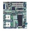
... controller: SI3124. 1 Server Board Features This chapter briefly describes the main features of important components and connections on the server board. ƒ The server boards SE7320SP2 and SE7525GP2 include dual-channel Serial ATA and dual- This chapter provides a photograph of the product, a list of server board features, and diagrams showing the location...
... controller: SI3124. 1 Server Board Features This chapter briefly describes the main features of important components and connections on the server board. ƒ The server boards SE7320SP2 and SE7525GP2 include dual-channel Serial ATA and dual- This chapter provides a photograph of the product, a list of server board features, and diagrams showing the location...

User Guide
Page 16
...x4 PCI-Express; Server Board SE7320SP2 Features Feature Description Processors Memory Chipset Support for two Intel® Xeon™ processors in two 604-pin Intel Xeon processor sockets with support for one...MHz system bus ƒ Four 184-pin DDR SDRAM Dual Inline Memory Module (DIMM) sockets ƒ Support for up to 8 GB Registered ECC system memory ƒ Support for ACPI:...instrumentation. ƒ Intel® Light-Guided Diagnostics on some FRU devices (processors, power) ƒ Port-80 Diagnostic LEDs displaying POST Codes Intel Server Board SE7320SP2 / SE7525GP2 User Guide 16 one...
...x4 PCI-Express; Server Board SE7320SP2 Features Feature Description Processors Memory Chipset Support for two Intel® Xeon™ processors in two 604-pin Intel Xeon processor sockets with support for one...MHz system bus ƒ Four 184-pin DDR SDRAM Dual Inline Memory Module (DIMM) sockets ƒ Support for up to 8 GB Registered ECC system memory ƒ Support for ACPI:...instrumentation. ƒ Intel® Light-Guided Diagnostics on some FRU devices (processors, power) ƒ Port-80 Diagnostic LEDs displaying POST Codes Intel Server Board SE7320SP2 / SE7525GP2 User Guide 16 one...

User Guide
Page 17
..., Power) ƒ Port-80 Diagnostic LEDs displaying POST Codes Intel Server Board SE7320SP2 / SE7525GP2 User Guide 17 one x16 PCI-Express; one 64-bit/66...SE7525GP2 Features Feature Description Processors Memory Chipset Support for two Intel® Xeon™ processors in two 604-pin Intel Xeon processor sockets with an 800 MHz system bus ƒ Four 184-pin DDR... SDRAM Dual Inline Memory Module (DIMM) sockets ƒ Support for up to 8 GB Registered ECC...
..., Power) ƒ Port-80 Diagnostic LEDs displaying POST Codes Intel Server Board SE7320SP2 / SE7525GP2 User Guide 17 one x16 PCI-Express; one 64-bit/66...SE7525GP2 Features Feature Description Processors Memory Chipset Support for two Intel® Xeon™ processors in two 604-pin Intel Xeon processor sockets with an 800 MHz system bus ƒ Four 184-pin DDR... SDRAM Dual Inline Memory Module (DIMM) sockets ƒ Support for up to 8 GB Registered ECC...

User Guide
Page 18
... CPU Power Connector GG: LCD Header N: Processor Socket 1 HH: SATA B1, B2, B3, B4 Connectors; Intel Server Board SE7320SP2 / SE7525GP2 Layout Intel Server Board SE7320SP2 / SE7525GP2 User Guide 18 SE7525GP2 server board only Z: Primary and Secondary ATA Connectors G: System Fan Header 2 AA: System Fan Header 3 H:... Slot 4, X: Floppy Drive Connector E: PCI Slot 5, 32-bit / 33 MHz Y: SATA A1, A2 Connectors F: x16 PCI-Express Slot 6; SE7320SP2 LX server board only O: Processor 1 Fan Header II: Battery P: Processor Socket 2 JJ: Jumper Block Q: System Fan Header 6 KK: Chassis...
... CPU Power Connector GG: LCD Header N: Processor Socket 1 HH: SATA B1, B2, B3, B4 Connectors; Intel Server Board SE7320SP2 / SE7525GP2 Layout Intel Server Board SE7320SP2 / SE7525GP2 User Guide 18 SE7525GP2 server board only Z: Primary and Secondary ATA Connectors G: System Fan Header 2 AA: System Fan Header 3 H:... Slot 4, X: Floppy Drive Connector E: PCI Slot 5, 32-bit / 33 MHz Y: SATA A1, A2 Connectors F: x16 PCI-Express Slot 6; SE7320SP2 LX server board only O: Processor 1 Fan Header II: Battery P: Processor Socket 2 JJ: Jumper Block Q: System Fan Header 6 KK: Chassis...
User Guide
Page 19
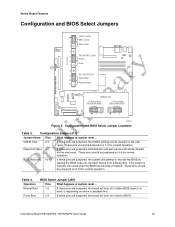
... pins should be cleared on the next reset. Normal Boot 1-2 If these pins are jumpered, the system will be jumpered on 5-6 for normal operation. Intel Server Board SE7320SP2 / SE7525GP2 User Guide 19 Configuration and BIOS Select Jumper Locations Table 3. Server Board Features Configuration and BIOS Select Jumpers CMOS CLEAR BMC Control 2 Force Erase...
... pins should be cleared on the next reset. Normal Boot 1-2 If these pins are jumpered, the system will be jumpered on 5-6 for normal operation. Intel Server Board SE7320SP2 / SE7525GP2 User Guide 19 Configuration and BIOS Select Jumper Locations Table 3. Server Board Features Configuration and BIOS Select Jumpers CMOS CLEAR BMC Control 2 Force Erase...

User Guide
Page 20
... board only) H. Back Panel Connectors The NIC LEDs at the right and left LED is on or blinking) 100 Mbps connection 1000 Mbps connection Intel Server Board SE7320SP2 / SE7525GP2 User Guide 20 Table 5. Mouse D. USB 1 B. NIC LEDs NIC NIC1 / NIC2 (Gigabit) LED Color Left LED Right LED LED State Off Solid Amber Blinking...
... board only) H. Back Panel Connectors The NIC LEDs at the right and left LED is on or blinking) 100 Mbps connection 1000 Mbps connection Intel Server Board SE7320SP2 / SE7525GP2 User Guide 20 Table 5. Mouse D. USB 1 B. NIC LEDs NIC NIC1 / NIC2 (Gigabit) LED Color Left LED Right LED LED State Off Solid Amber Blinking...

User Guide
Page 21
...F Q P O I D E N K M LJ CPU 2 Socket H I . System Fan Header 1 O. OEM RMC Connector H. Chassis Intrusion Connector J. Making Connections to the Server Board Intel Server Board SE7320SP2 / SE7525GP2 User Guide 21 Main Power Connector M. Floppy Drive Connector C. This is necessary because the hard drive cage contains one of the connections shown in...all of the front system fans. If you are installing your Server Board SE7320SP2 / SE7525GP2 into and the components you are installing. System Fan Headers 3 & 4 D. ATA Connectors F. +12V CPU ...
...F Q P O I D E N K M LJ CPU 2 Socket H I . System Fan Header 1 O. OEM RMC Connector H. Chassis Intrusion Connector J. Making Connections to the Server Board Intel Server Board SE7320SP2 / SE7525GP2 User Guide 21 Main Power Connector M. Floppy Drive Connector C. This is necessary because the hard drive cage contains one of the connections shown in...all of the front system fans. If you are installing your Server Board SE7320SP2 / SE7525GP2 into and the components you are installing. System Fan Headers 3 & 4 D. ATA Connectors F. +12V CPU ...
User Guide
Page 22
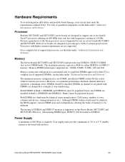
... installed. However, when mixing DIMM types, DDR333 will not boot. Memory The Server Boards SE7320SP2 and SE7525GP2 each provide four DDR266 / DDR333 DIMM sites in Bank 2 (DIMM2B and DIMM2A). Memory sizing and configuration is one or two Intel® Xeon™ processors utilizing an 800 MHz front side bus with higher current requirements are...
... installed. However, when mixing DIMM types, DDR333 will not boot. Memory The Server Boards SE7320SP2 and SE7525GP2 each provide four DDR266 / DDR333 DIMM sites in Bank 2 (DIMM2B and DIMM2A). Memory sizing and configuration is one or two Intel® Xeon™ processors utilizing an 800 MHz front side bus with higher current requirements are...

User Guide
Page 23
... Removing Memory The silkscreen on the board for instructions. 5. DIMM2A is the socket closest to the Safety Information at the beginning of the board. Intel Server Board SE7320SP2 / SE7525GP2 User Guide 23 Installing DIMMs To install DIMMs, follow these steps: 1. Turn off all peripheral devices connected to the server. Remove the server's cover...
... Removing Memory The silkscreen on the board for instructions. 5. DIMM2A is the socket closest to the Safety Information at the beginning of the board. Intel Server Board SE7320SP2 / SE7525GP2 User Guide 23 Installing DIMMs To install DIMMs, follow these steps: 1. Turn off all peripheral devices connected to the server. Remove the server's cover...

User Guide
Page 24
... the clips are pushed outward to disconnect. 13. Installing Memory TP00684 6. Holding the DIMM by the edges, remove it from its anti-static package. 8. Intel Server Board SE7320SP2 / SE7525GP2 User Guide 24 DIMM 1B DIMM 1A DIMM 2B DIMM 2A Figure 6. When the DIMM is inserted, push down on the top edge of...
... the clips are pushed outward to disconnect. 13. Installing Memory TP00684 6. Holding the DIMM by the edges, remove it from its anti-static package. 8. Intel Server Board SE7320SP2 / SE7525GP2 User Guide 24 DIMM 1B DIMM 1A DIMM 2B DIMM 2A Figure 6. When the DIMM is inserted, push down on the top edge of...

User Guide
Page 25
... your chassis documentation for a link to install or replace a processor instead of using the instructions that the processors are identical and of compatible processors. Intel Server Board SE7320SP2 / SE7525GP2 User Guide 25 When installing a second processor, verify that came with the metal chassis to the server. ESD and handling processors: Reduce the risk...
... your chassis documentation for a link to install or replace a processor instead of using the instructions that the processors are identical and of compatible processors. Intel Server Board SE7320SP2 / SE7525GP2 User Guide 25 When installing a second processor, verify that came with the metal chassis to the server. ESD and handling processors: Reduce the risk...

User Guide
Page 26
... socket lever completely. ✏ NOTE Make sure the alignment triangle mark and the alignment triangle cutout align correctly. Opening Socket Lever and Attaching Processor Intel Server Board SE7320SP2 / SE7525GP2 User Guide 26 Turn off all peripheral devices connected to the server. Lift the socket lever for instructions. 5. Installing the Processor 1. Observe the safety...
... socket lever completely. ✏ NOTE Make sure the alignment triangle mark and the alignment triangle cutout align correctly. Opening Socket Lever and Attaching Processor Intel Server Board SE7320SP2 / SE7525GP2 User Guide 26 Turn off all peripheral devices connected to the server. Lift the socket lever for instructions. 5. Installing the Processor 1. Observe the safety...