Service Guide
Page 5
...Intel® Server Board S5520HC „ Intel® Server Board S5520HCT „ Intel® Server Board S5500HCV „ Intel® Workstation Board S5520SC The Intel® Server Chassis SC5600BRP and SC5600LX are compatible with the following Intel® Server Boards: „ Intel® Server Board S5520HC „ Intel® Server Board S5520HCT „ Intel...for system technicians responsible for purchasing and using the Intel® Server Chassis SC5600. Chapter 2 provides instructions on cable routing, power supply specifications, and system environment requirements. Use this ...
...Intel® Server Board S5520HC „ Intel® Server Board S5520HCT „ Intel® Server Board S5500HCV „ Intel® Workstation Board S5520SC The Intel® Server Chassis SC5600BRP and SC5600LX are compatible with the following Intel® Server Boards: „ Intel® Server Board S5520HC „ Intel® Server Board S5520HCT „ Intel...for system technicians responsible for purchasing and using the Intel® Server Chassis SC5600. Chapter 2 provides instructions on cable routing, power supply specifications, and system environment requirements. Use this ...

Service Guide
Page 6
... more of the following items: „ Single fixed 670-W power supply installed in the chassis (SC5600Base), or (1+1) Hot-swap redundant 750-W power supply installed in the chassis (SC5600BRP and SC5600LX) „ Three fixed fans installed in the chassis (Intel® Server Chassis SC5600Base, Intel® Server Chassis SC5600BRP), or four hot-swap fans with fan cables installed in...
... more of the following items: „ Single fixed 670-W power supply installed in the chassis (SC5600Base), or (1+1) Hot-swap redundant 750-W power supply installed in the chassis (SC5600BRP and SC5600LX) „ Three fixed fans installed in the chassis (Intel® Server Chassis SC5600Base, Intel® Server Chassis SC5600BRP), or four hot-swap fans with fan cables installed in...

Service Guide
Page 9
... ...9 Peripheral Devices...11 Standard and Optional Hot-swap Drive Bays 12 Intel® Remote Management Module 3 12 Rack-mount Systems...12 Tower Passive Processor Heat Sink (FXXRGTHSINK 13 2 Hardware Installations and Upgrades 14 Before You Begin...14 Tools and Supplies Needed 14 System Reference ...14 Removing and Installing the Chassis Cover 15... Drive(s 41 Removing and Installing PCI Add-in Board(s 43 Removing PCI Add-in Board(s 43 Installing PCI Add-in Board(s 44 Replacing a Hot Swap Power Supply 48 Intel® Server Chassis SC5600 Service Guide ix
... ...9 Peripheral Devices...11 Standard and Optional Hot-swap Drive Bays 12 Intel® Remote Management Module 3 12 Rack-mount Systems...12 Tower Passive Processor Heat Sink (FXXRGTHSINK 13 2 Hardware Installations and Upgrades 14 Before You Begin...14 Tools and Supplies Needed 14 System Reference ...14 Removing and Installing the Chassis Cover 15... Drive(s 41 Removing and Installing PCI Add-in Board(s 43 Removing PCI Add-in Board(s 43 Installing PCI Add-in Board(s 44 Replacing a Hot Swap Power Supply 48 Intel® Server Chassis SC5600 Service Guide ix

Service Guide
Page 10
...Technical Reference 57 Power Supply Specification ...57 670-W Single Power Supply Input Voltage 57 670-W Single Power Supply Output Voltages 57 750-W Hot Swap Power Supply Input Voltages 57 750-W Hot Swap Power Supply Input Voltages 57 System Environmental Specification 58 Current Usage...59 Calculation Power Usage 59 ... Information 67 Safety Warnings and Cautions 67 Intended Application Uses ...68 Site Selection ...68 Equipment Handling Practices 68 Power and Electrical Warnings 68 System Access Warnings 69 Rack Mount Warnings 69 Electrostatic Discharge (ESD 69 Other Hazards...70...
...Technical Reference 57 Power Supply Specification ...57 670-W Single Power Supply Input Voltage 57 670-W Single Power Supply Output Voltages 57 750-W Hot Swap Power Supply Input Voltages 57 750-W Hot Swap Power Supply Input Voltages 57 System Environmental Specification 58 Current Usage...59 Calculation Power Usage 59 ... Information 67 Safety Warnings and Cautions 67 Intended Application Uses ...68 Site Selection ...68 Equipment Handling Practices 68 Power and Electrical Warnings 68 System Access Warnings 69 Rack Mount Warnings 69 Electrostatic Discharge (ESD 69 Other Hazards...70...
Service Guide
Page 13
... Table 10. Removing Hot Swap Power Supply from Chassis 51 Figure 58. Removing Hot Swap Power Supply from Hot Swap Power Supply Cage 52 Figure 61. Intel® Server Chassis SC5600Base Features 1 Table 2. Intel® Server Chassis SC5600BRP Features 2 Table 3. Front Control Panel LED Descriptions 8 Table 5. 670-W Power Supply Output Capability 57 Table 6. 750-W Hot Swap Power Supply Output Capability 58 Table 7. Removing...
... Table 10. Removing Hot Swap Power Supply from Chassis 51 Figure 58. Removing Hot Swap Power Supply from Hot Swap Power Supply Cage 52 Figure 61. Intel® Server Chassis SC5600Base Features 1 Table 2. Intel® Server Chassis SC5600BRP Features 2 Table 3. Front Control Panel LED Descriptions 8 Table 5. 670-W Power Supply Output Capability 57 Table 6. 750-W Hot Swap Power Supply Output Capability 58 Table 7. Removing...
Service Guide
Page 16
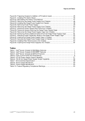
...on server/workstation board) ƒ One rear panel video port Table 2 summarizes the features of the Intel® Server Chassis SC5600BRP SKU. Intel® Server Chassis SC5600BRP Features Feature Dimensions Hard Drives Peripherals Control Panel (dependent on option selected) LEDs and displays (dependent on... USB ports with Front Control Panel ƒ Four back panel USB ports (depending on option selected) Power Supply Fans Processor Cooling USB 2.0 Video Description ƒ Intel® Local Control Panel (Optional) ƒ With Front Control Panel • NIC1 Activity • NIC2...
...on server/workstation board) ƒ One rear panel video port Table 2 summarizes the features of the Intel® Server Chassis SC5600BRP SKU. Intel® Server Chassis SC5600BRP Features Feature Dimensions Hard Drives Peripherals Control Panel (dependent on option selected) LEDs and displays (dependent on... USB ports with Front Control Panel ƒ Four back panel USB ports (depending on option selected) Power Supply Fans Processor Cooling USB 2.0 Video Description ƒ Intel® Local Control Panel (Optional) ƒ With Front Control Panel • NIC1 Activity • NIC2...

Service Guide
Page 17
... ƒ (1+1) hot-swap redundant PFC high-efficiency 750-W PMBus-compliant Intel® Server Chassis SC5600 Service Guide 3 Table 3. Intel® Server Chassis SC5600LX Features Feature Dimensions Hard Drives Peripherals Control Panel (dependent on option selected) LEDs and displays (dependent on option selected) Power Supply Description ƒ 17 inches high (Rack: 16.6 inches) ƒ 8.6 inches...
... ƒ (1+1) hot-swap redundant PFC high-efficiency 750-W PMBus-compliant Intel® Server Chassis SC5600 Service Guide 3 Table 3. Intel® Server Chassis SC5600LX Features Feature Dimensions Hard Drives Peripherals Control Panel (dependent on option selected) LEDs and displays (dependent on option selected) Power Supply Description ƒ 17 inches high (Rack: 16.6 inches) ƒ 8.6 inches...

Service Guide
Page 18
Server Chassis Features Fans Processor Heat Sink USB 2.0 Video Power Supply with integrated cooling fans, ƒ Second redundant 750-W module included ƒ Four hot-swap, redundant chassis fans: • Two 120-mm front fans • Two ... pans ƒ One air duct ƒ Processor heat sink is not included ƒ Passive tower processor heat sink(s) (FXXRGTHSINK) is required when used with compatible Intel® server/workstation board ƒ Supports up to 95-W processor ƒ Two front panel USB ports with Front Control Panel ƒ Four back panel USB...
Server Chassis Features Fans Processor Heat Sink USB 2.0 Video Power Supply with integrated cooling fans, ƒ Second redundant 750-W module included ƒ Four hot-swap, redundant chassis fans: • Two 120-mm front fans • Two ... pans ƒ One air duct ƒ Processor heat sink is not included ƒ Passive tower processor heat sink(s) (FXXRGTHSINK) is required when used with compatible Intel® server/workstation board ƒ Supports up to 95-W processor ƒ Two front panel USB ports with Front Control Panel ƒ Four back panel USB...

Service Guide
Page 19
PCI Add-in Card Panel 9. Rear Serial B Connector 8. 5.25-inch Device Bays (optional optical drive shown) 3. Air Duct and Rear Fixed Fan 10. Hard Disk Drive Cage Release Mechanisms (2) Figure 2. Intel® Server Chassis SC5600Base Components Location Intel® Server Chassis SC5600 Service Guide 5 Fixed Power Supply 7. Fixed Drive Cage 6-Drive 6. Front Panel USB/Serial B 4. Front Fixed Fans (2) 11. Front Control Panel 2. Fixed Drive Cage 4-Drive (accessory) 5. Component Identification Server Chassis Features 1.
PCI Add-in Card Panel 9. Rear Serial B Connector 8. 5.25-inch Device Bays (optional optical drive shown) 3. Air Duct and Rear Fixed Fan 10. Hard Disk Drive Cage Release Mechanisms (2) Figure 2. Intel® Server Chassis SC5600Base Components Location Intel® Server Chassis SC5600 Service Guide 5 Fixed Power Supply 7. Fixed Drive Cage 6-Drive 6. Front Panel USB/Serial B 4. Front Fixed Fans (2) 11. Front Control Panel 2. Fixed Drive Cage 4-Drive (accessory) 5. Component Identification Server Chassis Features 1.

Service Guide
Page 20
Front Control Panel 3. Hot-swap Fans - Server Chassis Features 1. Front Panel USB/Serial B 5. Large (2) 13. Intel® Server Chassis SC5600LX Components Location 6 Intel® Server Chassis SC5600 Service Guide Hot-swap Power Supply #2 8. PCI Add-in Card Panel 11. Hot-swap Drive Cage 6-Drive (accessory) 7. Hard Disk Drive Cage Release Mechanism (2) 2. Hot-swap Fans -Small...
Front Control Panel 3. Hot-swap Fans - Server Chassis Features 1. Front Panel USB/Serial B 5. Large (2) 13. Intel® Server Chassis SC5600LX Components Location 6 Intel® Server Chassis SC5600 Service Guide Hot-swap Power Supply #2 8. PCI Add-in Card Panel 11. Hot-swap Drive Cage 6-Drive (accessory) 7. Hard Disk Drive Cage Release Mechanism (2) 2. Hot-swap Fans -Small...

Service Guide
Page 22
..., voltage (power supply), voltage, thermal fault, and so forth Non-critical failure: Redundant fan failure, redundant power failure, non-critical power and voltage, and so forth AC Power off state or S5), and no degraded, non-critical, critical conditions exist* Hard drive activity Linked LAN activity Idle Linked LAN activity Idle Server identification; Intel® Local...
..., voltage (power supply), voltage, thermal fault, and so forth Non-critical failure: Redundant fan failure, redundant power failure, non-critical power and voltage, and so forth AC Power off state or S5), and no degraded, non-critical, critical conditions exist* Hard drive activity Linked LAN activity Idle Linked LAN activity Idle Server identification; Intel® Local...

Service Guide
Page 24
Server Chassis Features Callout A B C D E F Function Fixed Power Supply I/O Ports PCI Add-in Card Slots PCI Card Latch Rear Serial B Connector (optional) AC Power Connector / NOTE I/O ports vary, depending on the server/workstation board installed. Figure 6. Server Chassis Back 10 Intel® Server Chassis SC5600 Service Guide See your server board documentation for port identification.
Server Chassis Features Callout A B C D E F Function Fixed Power Supply I/O Ports PCI Add-in Card Slots PCI Card Latch Rear Serial B Connector (optional) AC Power Connector / NOTE I/O ports vary, depending on the server/workstation board installed. Figure 6. Server Chassis Back 10 Intel® Server Chassis SC5600 Service Guide See your server board documentation for port identification.

Service Guide
Page 62
... the handle (see letter "A" in Figure 54) to the power supply cage. Figure 53. Removing Hot Swap Power Supply from the defective hot swap power supply. 2. Installing Hot Swap Power Supply into the chassis, and make sure the green latch (see letter "B" in Figure 53) to the replaced power supply. 48 Intel® Server Chassis SC5600 Service Guide There are present...
... the handle (see letter "A" in Figure 54) to the power supply cage. Figure 53. Removing Hot Swap Power Supply from the defective hot swap power supply. 2. Installing Hot Swap Power Supply into the chassis, and make sure the green latch (see letter "B" in Figure 53) to the replaced power supply. 48 Intel® Server Chassis SC5600 Service Guide There are present...

Service Guide
Page 63
... from the chassis components and server board. 6. Remove the chassis cover. Removing Fixed Power Supply 7. See the Intel® server/workstation board Quick Start User's Guide or User Guide for connection locations. 10. Power up the server. servicing should be done by technically qualified personnel only. 1. For instructions, see letter "B"). Disconnect all peripheral devices...
... from the chassis components and server board. 6. Remove the chassis cover. Removing Fixed Power Supply 7. See the Intel® server/workstation board Quick Start User's Guide or User Guide for connection locations. 10. Power up the server. servicing should be done by technically qualified personnel only. 1. For instructions, see letter "B"). Disconnect all peripheral devices...

Service Guide
Page 64
... precautions at the beginning of this step for the appropriate connection location. 7. Figure 56. Removing Hot Swap Power Supply from the chassis. 50 Intel® Server Chassis SC5600 Service Guide See the Quick Start User's Guide or Service Guide provided with your... Intel server/workstation board for the second power supply. For instructions, see "Removing the Chassis Cover." 4. Repeat this book. 2. Power down the server and unplug all internal power cables from the chassis. Press on the green latch on the power supply (see letter "A" in ...
... precautions at the beginning of this step for the appropriate connection location. 7. Figure 56. Removing Hot Swap Power Supply from the chassis. 50 Intel® Server Chassis SC5600 Service Guide See the Quick Start User's Guide or Service Guide provided with your... Intel server/workstation board for the second power supply. For instructions, see "Removing the Chassis Cover." 4. Repeat this book. 2. Power down the server and unplug all internal power cables from the chassis. Press on the green latch on the power supply (see letter "A" in ...

Service Guide
Page 65
... Securing Hot Swap Power Supply Cage 9. Intel® Server Chassis SC5600 Service Guide 51 Remove the screws (see letters "A", "B", "C", "D", and "E" in the following figure) securing the power distribution board to feed the power cables through the chassis power supply bay while removing the hot swap power supply cage. Removing Hot Swap Power Supply Cage from Chassis 8. Figure 58. Removing Power Supply Filler Panel...
... Securing Hot Swap Power Supply Cage 9. Intel® Server Chassis SC5600 Service Guide 51 Remove the screws (see letters "A", "B", "C", "D", and "E" in the following figure) securing the power distribution board to feed the power cables through the chassis power supply bay while removing the hot swap power supply cage. Removing Hot Swap Power Supply Cage from Chassis 8. Figure 58. Removing Power Supply Filler Panel...

Service Guide
Page 66
... hot swap power supply cage into the chassis power supply bay. Attach the new power distribution board to the hot swap power supply cage, position the power distribution board screw holes to Hot Swap Power Supply Cage 12. Removing Power Distribution Board from Hot Swap Power Supply Cage 11. Attaching Power Distribution Board to the matching power supply cage mounting holes (see Step 13). 52 Intel®...
... hot swap power supply cage into the chassis power supply bay. Attach the new power distribution board to the hot swap power supply cage, position the power distribution board screw holes to Hot Swap Power Supply Cage 12. Removing Power Distribution Board from Hot Swap Power Supply Cage 11. Attaching Power Distribution Board to the matching power supply cage mounting holes (see Step 13). 52 Intel®...

Service Guide
Page 67
...to secure the power supply cage to the chassis (see letters "A", "B", "C", "D" and "E" in Chassis 13. Figure 64. Intel® Server Chassis SC5600 Service Guide 53 Hardware Installations and Upgrades Figure 62. Installing Filler Panel board on the Chassis 15. Securing Hot Swap Power Supply Cage to the... chassis (see Figure 65). Reinstall the filler panel board, and install the screws to secure the filler panel board to Chassis 14. Figure 63. Insert the hot swap power supplies into the chassis (see letters ...
...to secure the power supply cage to the chassis (see letters "A", "B", "C", "D" and "E" in Chassis 13. Figure 64. Intel® Server Chassis SC5600 Service Guide 53 Hardware Installations and Upgrades Figure 62. Installing Filler Panel board on the Chassis 15. Securing Hot Swap Power Supply Cage to the... chassis (see Figure 65). Reinstall the filler panel board, and install the screws to secure the filler panel board to Chassis 14. Figure 63. Insert the hot swap power supplies into the chassis (see letters ...

Service Guide
Page 68
... Press the latch at the rear of the chassis far enough so you must operate your server with a control panel installed. Inserting Hot Swap Power Supplies into the server. 19. For instructions, see "Removing the Chassis Cover." 4. swappable. Remove the chassis cover. Slide the control panel out ...panel and USB cable connectors at the back of the control panel. Use the following steps for replacing the front control panel and the Intel® Local Control Panel are noted. For instructions, see "Installing the Air Duct." 17. CAUTION The control panel is installed, remove ...
... Press the latch at the rear of the chassis far enough so you must operate your server with a control panel installed. Inserting Hot Swap Power Supplies into the server. 19. For instructions, see "Removing the Chassis Cover." 4. swappable. Remove the chassis cover. Slide the control panel out ...panel and USB cable connectors at the back of the control panel. Use the following steps for replacing the front control panel and the Intel® Local Control Panel are noted. For instructions, see "Installing the Air Duct." 17. CAUTION The control panel is installed, remove ...

Service Guide
Page 70
... Start User's Guide for cable connection locations. See your server has a hot swap power supply, connect the cables (that route toward the server/workstation board) to the chassis. If your Intel® Server/Workstation Board Service Guide or Quick Start User's Guide for cable connection ...locations. 56 Intel® Server Chassis SC5600 Service Guide See your server has a hot swap power supply, remove the cables (that cables do not obstruct fan airflow. Connecting Cables to Server/Workstation ...
... Start User's Guide for cable connection locations. See your server has a hot swap power supply, connect the cables (that route toward the server/workstation board) to the chassis. If your Intel® Server/Workstation Board Service Guide or Quick Start User's Guide for cable connection ...locations. 56 Intel® Server Chassis SC5600 Service Guide See your server has a hot swap power supply, remove the cables (that cables do not obstruct fan airflow. Connecting Cables to Server/Workstation ...