
Service Guide
Page 9
... Fans 23 Removing and Installing a DVD- or CD-ROM Drive 25 Removing and Installing Fixed Hard Drive(s 27 Removing Fixed Hard Drive(s 27 Installing Fixed Hard Drive(s 31 Routing Power Cables to Fixed Drives 37 Routing Data Cables to Fixed Drives 38 Removing and Installing Hot Swap Drive(s 39 Removing Hot Swap Drive(s 39 Installing Hot Swap Drive(s 41 Removing and Installing PCI Add-in Board(s 43 Removing PCI Add-in Board(s 43 Installing PCI Add-in Board(s 44 Replacing a Hot Swap Power Supply 48 Intel® Server Chassis SC5600 Service Guide...
... Fans 23 Removing and Installing a DVD- or CD-ROM Drive 25 Removing and Installing Fixed Hard Drive(s 27 Removing Fixed Hard Drive(s 27 Installing Fixed Hard Drive(s 31 Routing Power Cables to Fixed Drives 37 Routing Data Cables to Fixed Drives 38 Removing and Installing Hot Swap Drive(s 39 Removing Hot Swap Drive(s 39 Installing Hot Swap Drive(s 41 Removing and Installing PCI Add-in Board(s 43 Removing PCI Add-in Board(s 43 Installing PCI Add-in Board(s 44 Replacing a Hot Swap Power Supply 48 Intel® Server Chassis SC5600 Service Guide...

Service Guide
Page 12
... in board 43 xii Intel® Server Chassis SC5600 Service Guide Preparing Chassis for Removal of Fixed Drive Cage 28 Figure 24. Server Chassis Back ...10 Figure 7. Installing the Chassis Cover 16 Figure 10. Removing the Air Duct 19 Figure 13. Unlocking and Opening Upper Door of PCI add-in Drive Carrier 40 Figure 44. Inserting Drive/Slide Assembly into Hot Swap Cage 42 Figure 49. Removing Drive Carrier...
... in board 43 xii Intel® Server Chassis SC5600 Service Guide Preparing Chassis for Removal of Fixed Drive Cage 28 Figure 24. Server Chassis Back ...10 Figure 7. Installing the Chassis Cover 16 Figure 10. Removing the Air Duct 19 Figure 13. Unlocking and Opening Upper Door of PCI add-in Drive Carrier 40 Figure 44. Inserting Drive/Slide Assembly into Hot Swap Cage 42 Figure 49. Removing Drive Carrier...

Service Guide
Page 21
Status LED (bi-color) I. ID LED Toggle Switch B. ID LED (blue) H. Reset Button C. NIC1 Activity LED (green) D. Front Control Panel Intel® Server Chassis SC5600 Service Guide 7 Front Control Panel Server Chassis Features A. Hard Drive Activity LED (green) F. Power Button E. NIC2 Activity LED (green) G. NMI Button Figure 4.
Status LED (bi-color) I. ID LED Toggle Switch B. ID LED (blue) H. Reset Button C. NIC1 Activity LED (green) D. Front Control Panel Intel® Server Chassis SC5600 Service Guide 7 Front Control Panel Server Chassis Features A. Hard Drive Activity LED (green) F. Power Button E. NIC2 Activity LED (green) G. NMI Button Figure 4.

Service Guide
Page 29
... it stops. Removing the Chassis Cover Intel® Server Chassis SC5600 Service Guide 15 See "Appendix B: Safety Information". 2. Observe the safety and ESD precautions at the top of the chassis (see letter "B"), slide the top cover back until it is installed, remove the access cover screw (see letter "A" in the following figure). Before removing the top cover, power down the server and unplug...
... it stops. Removing the Chassis Cover Intel® Server Chassis SC5600 Service Guide 15 See "Appendix B: Safety Information". 2. Observe the safety and ESD precautions at the top of the chassis (see letter "B"), slide the top cover back until it is installed, remove the access cover screw (see letter "A" in the following figure). Before removing the top cover, power down the server and unplug...
Service Guide
Page 32
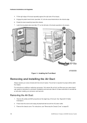
... server chassis with the air duct in place. For instructions, see letter "E") on page 26. 18 Intel® Server Chassis SC5600 Service Guide Latch the two plastic tabs (see "Removing the Chassis Cover" on the left side of the chassis. 5. See "Appendix B: Safety Information". 2. Removing the Air Duct 1. Installing the Front Bezel Removing and Installing the Air Duct Always operate your processor and heat sink. Power...
... server chassis with the air duct in place. For instructions, see letter "E") on page 26. 18 Intel® Server Chassis SC5600 Service Guide Latch the two plastic tabs (see "Removing the Chassis Cover" on the left side of the chassis. 5. See "Appendix B: Safety Information". 2. Removing the Air Duct 1. Installing the Front Bezel Removing and Installing the Air Duct Always operate your processor and heat sink. Power...

Service Guide
Page 35
... snap-in the following figure) or 120-mm (see letter "A" in bracket. For instructions, see "Removing the Chassis Cover." 4. Hardware Installations and Upgrades Figure 14. To replace the rear chassis fan, remove the air duct. Installing the Air Duct into Intel® Server Chassis SC5600LX / NOTE Use care to the Intel® Server Chassis SC5600Base and Intel® Server Chassis SC5600BRP configurations. 1. Remove the 92-mm (see letters "B" and "C") fixed fan from the server board. 5.
... snap-in the following figure) or 120-mm (see letter "A" in bracket. For instructions, see "Removing the Chassis Cover." 4. Hardware Installations and Upgrades Figure 14. To replace the rear chassis fan, remove the air duct. Installing the Air Duct into Intel® Server Chassis SC5600LX / NOTE Use care to the Intel® Server Chassis SC5600Base and Intel® Server Chassis SC5600BRP configurations. 1. Remove the 92-mm (see letters "B" and "C") fixed fan from the server board. 5.

Service Guide
Page 36
...; Server Chassis SC5600LX configurations. See the Quick Start User's Guide or Service Guide provided with fixed fans. Install a new 92-mm or 120-mm fixed fan. 8. For instructions, see "Installing the Air Duct." 10. Install the air duct if it was removed in the Intel® Server Chassis SC5600LX. 1. The Intel® Server Chassis SC5600Base and Intel® Server Chassis SC5400BRP configurations ship with your Intel® server/workstation board for the appropriate connection location. 9. Hardware Installations and Upgrades...
...; Server Chassis SC5600LX configurations. See the Quick Start User's Guide or Service Guide provided with fixed fans. Install a new 92-mm or 120-mm fixed fan. 8. For instructions, see "Installing the Air Duct." 10. Install the air duct if it was removed in the Intel® Server Chassis SC5600LX. 1. The Intel® Server Chassis SC5600Base and Intel® Server Chassis SC5400BRP configurations ship with your Intel® server/workstation board for the appropriate connection location. 9. Hardware Installations and Upgrades...

Service Guide
Page 38
... this book. 2. Remove the chassis cover. For instructions, see "Removing and Installing the Front Bezel." 5. For instructions, see "Removing the Chassis Cover." 4. Remove the slides from the DVD or CD-ROM drive by pressing in Figure 18). A gentle pull should release the slide from the drive (see letter "A" in on the drive. 24 Intel® Server Chassis SC5600 Service Guide or CD-ROM Drive 1. Power down the server and unplug...
... this book. 2. Remove the chassis cover. For instructions, see "Removing and Installing the Front Bezel." 5. For instructions, see "Removing the Chassis Cover." 4. Remove the slides from the DVD or CD-ROM drive by pressing in Figure 18). A gentle pull should release the slide from the drive (see letter "A" in on the drive. 24 Intel® Server Chassis SC5600 Service Guide or CD-ROM Drive 1. Power down the server and unplug...

Service Guide
Page 39
...." 9. For instructions, see "Installing the Chassis Cover." 10. Figure 19. Installing a DVD- Remove the chassis cover. Removing DVD or CD-ROM Drive 7. If you are not replacing with another drive, re-attach a pair of this book. 2. For instructions, see "Removing and Installing the Front Bezel." 5. Intel® Server Chassis SC5600 Service Guide 25 or CD-ROM Drive 1. Install the front bezel. Hardware Installations and Upgrades Figure 18. Power up the server. Power down the server and...
...." 9. For instructions, see "Installing the Chassis Cover." 10. Figure 19. Installing a DVD- Remove the chassis cover. Removing DVD or CD-ROM Drive 7. If you are not replacing with another drive, re-attach a pair of this book. 2. For instructions, see "Removing and Installing the Front Bezel." 5. Intel® Server Chassis SC5600 Service Guide 25 or CD-ROM Drive 1. Install the front bezel. Hardware Installations and Upgrades Figure 18. Power up the server. Power down the server and...

Service Guide
Page 40
... device bay until the slides lock into the server. 12. For instructions, see "Removing and Installing the Front Bezel." 10. Plug all peripheral devices and the AC power cable into place. 8. Power up the server. 26 Intel® Server Chassis SC5600 Service Guide Install the front bezel. For instructions, see "Installing the Chassis Cover." 11. or CD-ROM drive. Connect power and data cables. 9. Install the chassis cover. Hardware Installations and Upgrades Figure...
... device bay until the slides lock into the server. 12. For instructions, see "Removing and Installing the Front Bezel." 10. Plug all peripheral devices and the AC power cable into place. 8. Power up the server. 26 Intel® Server Chassis SC5600 Service Guide Install the front bezel. For instructions, see "Installing the Chassis Cover." 11. or CD-ROM drive. Connect power and data cables. 9. Install the chassis cover. Hardware Installations and Upgrades Figure...

Service Guide
Page 41
.... / NOTE As an alternative, you may also fully remove the drive cage from Chassis Intel® Server Chassis SC5600 Service Guide 27 Remove power and data cables from the drive bay slot in the chassis. Take care, however, to release the fixed drive cage (see letter "B") so it is installed, remove the front bezel. Figure 22. For instructions, see "Removing and Installing the Front Bezel." 5. If it easier to...
.... / NOTE As an alternative, you may also fully remove the drive cage from Chassis Intel® Server Chassis SC5600 Service Guide 27 Remove power and data cables from the drive bay slot in the chassis. Take care, however, to release the fixed drive cage (see letter "B") so it is installed, remove the front bezel. Figure 22. For instructions, see "Removing and Installing the Front Bezel." 5. If it easier to...

Service Guide
Page 45
.... Install the front bezel. Plug all peripheral devices and the AC power cable. 3. Installing Fixed Hard Drive(s) 1. Power up the server. Power down the server and unplug all peripheral devices and the AC power cable into the chassis. 16. Intel® Server Chassis SC5600 Service Guide 31 Reinstall the fixed hard drive into the server. 20. Pull the drive cage out about two inches (see letter "A" Figure 30). Remove the chassis cover...
.... Install the front bezel. Plug all peripheral devices and the AC power cable. 3. Installing Fixed Hard Drive(s) 1. Power up the server. Power down the server and unplug all peripheral devices and the AC power cable into the chassis. 16. Intel® Server Chassis SC5600 Service Guide 31 Reinstall the fixed hard drive into the server. 20. Pull the drive cage out about two inches (see letter "A" Figure 30). Remove the chassis cover...

Service Guide
Page 50
Hardware Installations and Upgrades Figure 38. Connect the power and data cables to the connectors on page 27. 19. Power up the server. 36 Intel® Server Chassis SC5600 Service Guide Re-install the fixed drive cage into the server. 20. Install the chassis cover. Install the front bezel. For instructions, see "Removing and Installing the Front Bezel." 18. Tightening Thumb Screw 15. Plug all peripheral devices and the AC power cable into the chassis. 16. For instructions, see "Installing the Chassis Cover" on the hard drive(s). 17.
Hardware Installations and Upgrades Figure 38. Connect the power and data cables to the connectors on page 27. 19. Power up the server. 36 Intel® Server Chassis SC5600 Service Guide Re-install the fixed drive cage into the server. 20. Install the chassis cover. Install the front bezel. For instructions, see "Removing and Installing the Front Bezel." 18. Tightening Thumb Screw 15. Plug all peripheral devices and the AC power cable into the chassis. 16. For instructions, see "Installing the Chassis Cover" on the hard drive(s). 17.

Service Guide
Page 51
Hardware Installations and Upgrades Routing Power Cables to Fixed Drives Route the longest power cables to the 6-drive bay and shorter cables to Fixed Drives Intel® Server Chassis SC5600 Service Guide 37 Routing Power Cables to the 4-drive bay and upper device bay. Figure 39.
Hardware Installations and Upgrades Routing Power Cables to Fixed Drives Route the longest power cables to the 6-drive bay and shorter cables to Fixed Drives Intel® Server Chassis SC5600 Service Guide 37 Routing Power Cables to the 4-drive bay and upper device bay. Figure 39.

Service Guide
Page 63
... safety and ESD precautions at the beginning of this book. 2. Removing Fixed Power Supply 7. Figure 55. Remove the fixed power supply (see "Installing the Chassis Cover." 13. For instructions, see letter "A" in Figure 55). See the Intel® server/workstation board Quick Start User's Guide or User Guide for connection locations. 10. Hardware Installations and Upgrades Replacing a Fixed Power Supply WARNING Hazardous voltage, current, and energy levels are no user-serviceable parts inside the power supply.
... safety and ESD precautions at the beginning of this book. 2. Removing Fixed Power Supply 7. Figure 55. Remove the fixed power supply (see "Installing the Chassis Cover." 13. For instructions, see letter "A" in Figure 55). See the Intel® server/workstation board Quick Start User's Guide or User Guide for connection locations. 10. Hardware Installations and Upgrades Replacing a Fixed Power Supply WARNING Hazardous voltage, current, and energy levels are no user-serviceable parts inside the power supply.

Service Guide
Page 64
... Figure 56) to the chassis, and remove the power supply filler panel from the chassis. Hardware Installations and Upgrades Replacing the Hot Swap Power Supply Power Distribution Board WARNING Hazardous voltage, current, and energy levels are no user-serviceable parts inside the power supply. There are present inside it; Repeat this book. 2. See the Quick Start User's Guide or Service Guide provided with your Intel server/workstation board for the second power supply. servicing should be done by...
... Figure 56) to the chassis, and remove the power supply filler panel from the chassis. Hardware Installations and Upgrades Replacing the Hot Swap Power Supply Power Distribution Board WARNING Hazardous voltage, current, and energy levels are no user-serviceable parts inside the power supply. There are present inside it; Repeat this book. 2. See the Quick Start User's Guide or Service Guide provided with your Intel server/workstation board for the second power supply. servicing should be done by...

Service Guide
Page 69
... devices and the AC power cable into the chassis. 9. Remove the mounting screws, starting with your chassis depends upon the chassis model. Re-install the air duct. For instructions, see "Installing the Chassis Cover." 14. For instructions, see "Removing PCI Add-in the Intel® server/workstation board Service Guide and/or Quick Start User's Guide. 8. For instructions, see "Installing the Air Duct" on page 32. 11. Power up the server. Intel® Server Chassis SC5600 Service Guide 55
... devices and the AC power cable into the chassis. 9. Remove the mounting screws, starting with your chassis depends upon the chassis model. Re-install the air duct. For instructions, see "Installing the Chassis Cover." 14. For instructions, see "Removing PCI Add-in the Intel® server/workstation board Service Guide and/or Quick Start User's Guide. 8. For instructions, see "Installing the Air Duct" on page 32. 11. Power up the server. Intel® Server Chassis SC5600 Service Guide 55
Service Guide
Page 83
... available but not the board wrapper. Intel® Server Chassis SC5600 Service Guide 69 Caution: If the server has been running, any surface. The equipment rack must be anchored to an unmovable support to chassis ground -- Extend only one is supplied with hot component(s) during a hot-plug installation, be installed according to the power supply being replaced before removing the power supply from the server, place the board component side up...
... available but not the board wrapper. Intel® Server Chassis SC5600 Service Guide 69 Caution: If the server has been running, any surface. The equipment rack must be anchored to an unmovable support to chassis ground -- Extend only one is supplied with hot component(s) during a hot-plug installation, be installed according to the power supply being replaced before removing the power supply from the server, place the board component side up...
Service Guide
Page 111
... support site includes: • Latest BIOS, firmware, drivers and utilities • Product documentation, installation and quick start guides • Full product specifications, technical advisories and errata • Compatibility documentation for memory, hardware add-in cards, chassis support matrix, and operating systems • Server and chassis accessory parts list for ordering upgrades or spare parts • A searchable knowledgebase to search for product information throughout the support site 2. Charges may apply. Intel customer support...
... support site includes: • Latest BIOS, firmware, drivers and utilities • Product documentation, installation and quick start guides • Full product specifications, technical advisories and errata • Compatibility documentation for memory, hardware add-in cards, chassis support matrix, and operating systems • Server and chassis accessory parts list for ordering upgrades or spare parts • A searchable knowledgebase to search for product information throughout the support site 2. Charges may apply. Intel customer support...
Service Guide
Page 117
... time to make repairs or to replace Product or to refund the then-current value of any implied warranties that may not apply to Intel's publicly available specifications for otherwise in material and workmanship and will substantially conform to you. Intel® Server Chassis SC5600 Service Guide 103 Appendix F: Warranty Appendix F: Warranty Limited Warranty for Intel® Chassis Subassembly Products Intel warrants that the...
... time to make repairs or to replace Product or to refund the then-current value of any implied warranties that may not apply to Intel's publicly available specifications for otherwise in material and workmanship and will substantially conform to you. Intel® Server Chassis SC5600 Service Guide 103 Appendix F: Warranty Appendix F: Warranty Limited Warranty for Intel® Chassis Subassembly Products Intel warrants that the...
