
User Guide
Page 3
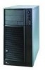
... reparing this chapter for step-bystep instructions and diagrams for replacing fans, power supply and other components. In this chapter, you will find a list of the server chassis features, photos of accessories or other components you will find information on the Intel® Entry Server Chassis SC5275-E. In this chapter, you may need, troubleshooting information, and instructions on how...
... reparing this chapter for step-bystep instructions and diagrams for replacing fans, power supply and other components. In this chapter, you will find a list of the server chassis features, photos of accessories or other components you will find information on the Intel® Entry Server Chassis SC5275-E. In this chapter, you may need, troubleshooting information, and instructions on how...

User Guide
Page 5
... sure that you must adhere to ensure and maintain compliance with existing product certifications and approvals. We recommend that the chassis, power supply, and other modules have passed EMC testing using this guide or any other resource as : medical, industrial, telecommunications,... provide some ESD protection by wearing an antistatic wrist Intel® Entry Server Chassis SC5275-E User Guide v Use of other products / components will most likely result in noncompliance with your local Intel Representative. To remove power from system, you perform all procedures in offices, ...
... sure that you must adhere to ensure and maintain compliance with existing product certifications and approvals. We recommend that the chassis, power supply, and other modules have passed EMC testing using this guide or any other resource as : medical, industrial, telecommunications,... provide some ESD protection by wearing an antistatic wrist Intel® Entry Server Chassis SC5275-E User Guide v Use of other products / components will most likely result in noncompliance with your local Intel Representative. To remove power from system, you perform all procedures in offices, ...

User Guide
Page 6
... the instructions. Some jumpers have a small tab on top that slips over any surface. If your server when handling parts. Intel® Entry Server Chassis SC5275-E User Guide vi Gripping the wide sides can be extremely sensitive to ESD. The power supply in this document before performing any of the system, follow these steps: 1. The socket outlet that...
... the instructions. Some jumpers have a small tab on top that slips over any surface. If your server when handling parts. Intel® Entry Server Chassis SC5275-E User Guide vi Gripping the wide sides can be extremely sensitive to ESD. The power supply in this document before performing any of the system, follow these steps: 1. The socket outlet that...

User Guide
Page 7
...the power supply cord(s), because they serve as the product's main power disconnect. Isolated from strong electromagnetic fields produced by wearing an antistatic wrist strap attached to the system. Remove and save all external cables and the AC power cord(s) to chassis ground ...loose tools or parts inside the system. 5. Replace only with care. Preface 5. Check first to manufacturer's instructions. Intel® Entry Server Chassis SC5275-E User Guide vii Contact should be made with the same or equivalent type recommended by the equipment manufacturer. In regions...
...the power supply cord(s), because they serve as the product's main power disconnect. Isolated from strong electromagnetic fields produced by wearing an antistatic wrist strap attached to the system. Remove and save all external cables and the AC power cord(s) to chassis ground ...loose tools or parts inside the system. 5. Replace only with care. Preface 5. Check first to manufacturer's instructions. Intel® Entry Server Chassis SC5275-E User Guide vii Contact should be made with the same or equivalent type recommended by the equipment manufacturer. In regions...

User Guide
Page 15
... 3.5-inch Hot Swap Drive Bay 5 Accessories and Order Codes 5 Power Supply ...6 Checking the Power Cord 6 Chassis Security ...6 Monitoring ...6 Mechanical Locks...7 2 Setting Up the Chassis 9 Tools and Supplies Needed ...9 Installation Safety Instructions 9 Safety: Before You Remove the ...Server Board 23 Installing an Add-in Board ...24 Install the Front Bezel ...26 Install the Access Cover...27 3 Maintaining Your Server 29 Tools and Supplies Needed 29 Safety: Before You Remove the Access Cover(s 29 Warnings and Cautions...29 Replacing Fans ...31 Intel® Entry Server Chassis SC5275...
... 3.5-inch Hot Swap Drive Bay 5 Accessories and Order Codes 5 Power Supply ...6 Checking the Power Cord 6 Chassis Security ...6 Monitoring ...6 Mechanical Locks...7 2 Setting Up the Chassis 9 Tools and Supplies Needed ...9 Installation Safety Instructions 9 Safety: Before You Remove the ...Server Board 23 Installing an Add-in Board ...24 Install the Front Bezel ...26 Install the Access Cover...27 3 Maintaining Your Server 29 Tools and Supplies Needed 29 Safety: Before You Remove the Access Cover(s 29 Warnings and Cautions...29 Replacing Fans ...31 Intel® Entry Server Chassis SC5275...

User Guide
Page 16
Installing the I/O Shield 13 Intel® Entry Server Chassis SC5275-E User Guide xvi Contents Replacing a Front System Fan 31 Replacing a Rear System Fan 32 Replacing the Power Supply 33 Replacing the Front Panel Board 34 Replacing the USB Cable ...36 4 Technical Reference 39 Power Supply Specifications 39 600 Watt Single Power Supply Input Voltages 39 600 Watt Single Power Supply Output Voltages 39 System...
Installing the I/O Shield 13 Intel® Entry Server Chassis SC5275-E User Guide xvi Contents Replacing a Front System Fan 31 Replacing a Rear System Fan 32 Replacing the Power Supply 33 Replacing the Front Panel Board 34 Replacing the USB Cable ...36 4 Technical Reference 39 Power Supply Specifications 39 600 Watt Single Power Supply Input Voltages 39 600 Watt Single Power Supply Output Voltages 39 System...

User Guide
Page 17
... Front Panel Board 35 Figure 23. Table 4. Table 7. Feature Summary ...1 LED Description ...3 Accessories and Order Codes 5 Power Supply System Output Capability 39 Environmental Specifications 40 Power Usage Worksheet 1 43 Power Usage Worksheet 2 44 Product Certification Markings 46 Intel® Entry Server Chassis SC5275-E User Guide xvii Removing a Drive Cage 19 Figure 12. Installing the Front Bezel 26 Figure 16...
... Front Panel Board 35 Figure 23. Table 4. Table 7. Feature Summary ...1 LED Description ...3 Accessories and Order Codes 5 Power Supply System Output Capability 39 Environmental Specifications 40 Power Usage Worksheet 1 43 Power Usage Worksheet 2 44 Product Certification Markings 46 Intel® Entry Server Chassis SC5275-E User Guide xvii Removing a Drive Cage 19 Figure 12. Installing the Front Bezel 26 Figure 16...

User Guide
Page 19
...to five 1-inch high, SCSI hot-swap hard drives or four SATA drives. Flat head 6-32 x 5mm [.200] B. Cooling Two system fans inside the chassis and one power supply fan provide cooling and airflow. Flat head M3 x 5mm [.200] C. Screw Description Feature Summary Table 1. A hard drive bay cage designed to hold half-... pair of 5.25inch external drive rails, four different types of mounting screws, and two brackets for up to seven expansion slots can be used; Power Supply 600 Watt PFC power supply. Intel® Entry Server Chassis SC5275-E User Guide 1 A BC TP00835 A.
...to five 1-inch high, SCSI hot-swap hard drives or four SATA drives. Flat head 6-32 x 5mm [.200] B. Cooling Two system fans inside the chassis and one power supply fan provide cooling and airflow. Flat head M3 x 5mm [.200] C. Screw Description Feature Summary Table 1. A hard drive bay cage designed to hold half-... pair of 5.25inch external drive rails, four different types of mounting screws, and two brackets for up to seven expansion slots can be used; Power Supply 600 Watt PFC power supply. Intel® Entry Server Chassis SC5275-E User Guide 1 A BC TP00835 A.
User Guide
Page 22
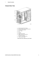
Power supply E. Expansion slot covers H. Serial B port knockout J. AC input power connector D. Fan F. ICMB or external SCSI knockout I /O ports* G. Location to install padlock loop K. 1 Chassis Description Chassis Rear View A B C D E F TP00834 A. I . Chassis intrusion switch * Items shown may be different in your chassis. Alternate ICMB or external SCSI knockout C. Intel® Entry Server Chassis SC5275-E User Guide 4 Alternate Serial B port knockout B.
Power supply E. Expansion slot covers H. Serial B port knockout J. AC input power connector D. Fan F. ICMB or external SCSI knockout I /O ports* G. Location to install padlock loop K. 1 Chassis Description Chassis Rear View A B C D E F TP00834 A. I . Chassis intrusion switch * Items shown may be different in your chassis. Alternate ICMB or external SCSI knockout C. Intel® Entry Server Chassis SC5275-E User Guide 4 Alternate Serial B port knockout B.
User Guide
Page 24
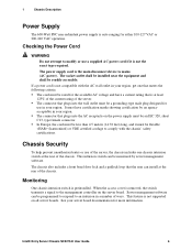
... marks showing certification by server management software. This intrusion switch can be an IEC 320, sheet C13, type female connector. 1 Chassis Description Power Supply The 600-Watt PFC non-redundant power supply is auto ranging for more information. The power supply cord is removed, the... to modify or use in a number of the chassis. Server management software can install at the rear of the server. If a power cord is not supported on the server board. The connector that is preinstalled. Intel® Entry Server Chassis SC5275-E User Guide 6 In Europe, the cord must...
... marks showing certification by server management software. This intrusion switch can be an IEC 320, sheet C13, type female connector. 1 Chassis Description Power Supply The 600-Watt PFC non-redundant power supply is auto ranging for more information. The power supply cord is removed, the... to modify or use in a number of the chassis. Server management software can install at the rear of the server. If a power cord is not supported on the server board. The connector that is preinstalled. Intel® Entry Server Chassis SC5275-E User Guide 6 In Europe, the cord must...

User Guide
Page 27
Read and adhere to remove only the left access cover, not the cover at the right. Intel® Entry Server Chassis SC5275-E User Guide 9 Tools and Supplies Needed Phillips (cross head) screwdriver (#2 bit) Small flathead screwdriver Antistatic wrist strap (recommended) Installation Safety ... this assembly. If you do not follow these instructions and the instructions supplied with other regional product laws and regulations. Provide some electrostatic discharge (ESD) protection by pressing the power button on the back of replacing the front panel board (discussed in ...
Read and adhere to remove only the left access cover, not the cover at the right. Intel® Entry Server Chassis SC5275-E User Guide 9 Tools and Supplies Needed Phillips (cross head) screwdriver (#2 bit) Small flathead screwdriver Antistatic wrist strap (recommended) Installation Safety ... this assembly. If you do not follow these instructions and the instructions supplied with other regional product laws and regulations. Provide some electrostatic discharge (ESD) protection by pressing the power button on the back of replacing the front panel board (discussed in ...

User Guide
Page 28
... may short out. Turn off the AC power. servicing should integrate and configure the server. CAUTIONS ESD can result. Always handle boards carefully. Hold boards only by wearing an antistatic wrist strap attached to access components inside the power supply. If they do, this chapter only at an ESD workstation. Intel® Entry Server Chassis SC5275-E User Guide 10
... may short out. Turn off the AC power. servicing should integrate and configure the server. CAUTIONS ESD can result. Always handle boards carefully. Hold boards only by wearing an antistatic wrist strap attached to access components inside the power supply. If they do, this chapter only at an ESD workstation. Intel® Entry Server Chassis SC5275-E User Guide 10

User Guide
Page 31
... match the external I /O Shield TP00074 Intel® Entry Server Chassis SC5275-E User Guide 13 2 Setting Up the Chassis Install the I/O Shield ✏ NOTE An ATX 2.03-compliant I/O shield should be provided with the corresponding I/O connectors on the inner chassis wall. 4. The shield fits the rectangular...inside of the server. Installing the I /O connectors (e.g., keyboard and mouse). 1. The shield has cutouts that the dotted groove is outside the chassis wall and the lip of the chassis. Make sure the I/O shield snaps into the opening near the power supply in place, ...
... match the external I /O Shield TP00074 Intel® Entry Server Chassis SC5275-E User Guide 13 2 Setting Up the Chassis Install the I/O Shield ✏ NOTE An ATX 2.03-compliant I/O shield should be provided with the corresponding I/O connectors on the inner chassis wall. 4. The shield fits the rectangular...inside of the server. Installing the I /O connectors (e.g., keyboard and mouse). 1. The shield has cutouts that the dotted groove is outside the chassis wall and the lip of the chassis. Make sure the I/O shield snaps into the opening near the power supply in place, ...

User Guide
Page 47
..., and communication cables. Hazardous voltage, current, and energy levels are no user-serviceable parts inside the power supply. Intel® Entry Server Chassis SC5275-E User Guide 29 Only a technically qualified person should be present on the front of the chassis. 5. Tools and Supplies Needed Phillips (cross head) screwdriver (#2 bit) Small flathead screwdriver Antistatic wrist strap (recommended) Needle-nosed pliers...
..., and communication cables. Hazardous voltage, current, and energy levels are no user-serviceable parts inside the power supply. Intel® Entry Server Chassis SC5275-E User Guide 29 Only a technically qualified person should be present on the front of the chassis. 5. Tools and Supplies Needed Phillips (cross head) screwdriver (#2 bit) Small flathead screwdriver Antistatic wrist strap (recommended) Needle-nosed pliers...

User Guide
Page 49
...at the side of the cage. 6. Disconnect the cables from the chassis. Remove the bezel. 3. Slide the fan out through the fan opening. Replacing the Front System Fan in place. 8. The power supply fan(s) are removing. Use a flat-head screwdriver to remove the ...server board. 4. 3 Maintaining Your Server Replacing Fans The chassis contains two replaceable system fans. Replacing a Front System Fan Standard Hard Drive Bay Cage The front system fan is not necessary to pry up the four nylon rivets that hold the fan in a Standard Drive Cage Intel® Entry Server Chassis SC5275...
...at the side of the cage. 6. Disconnect the cables from the chassis. Remove the bezel. 3. Slide the fan out through the fan opening. Replacing the Front System Fan in place. 8. The power supply fan(s) are removing. Use a flat-head screwdriver to remove the ...server board. 4. 3 Maintaining Your Server Replacing Fans The chassis contains two replaceable system fans. Replacing a Front System Fan Standard Hard Drive Bay Cage The front system fan is not necessary to pry up the four nylon rivets that hold the fan in a Standard Drive Cage Intel® Entry Server Chassis SC5275...

User Guide
Page 51
... locations Figure 18. servicing should be done by technically qualified personnel. There are present inside the chassis. 4. Disconnect the A/C power from the chassis. 7. Remove the left access cover. 3. Remove the two screws holding the front of the power supply to the back of the chassis, two inside the chassis). 9. Replacing the AC Power Supply TP00068 Intel® Entry Server Chassis SC5275-E User Guide 33
... locations Figure 18. servicing should be done by technically qualified personnel. There are present inside the chassis. 4. Disconnect the A/C power from the chassis. 7. Remove the left access cover. 3. Remove the two screws holding the front of the power supply to the back of the chassis, two inside the chassis). 9. Replacing the AC Power Supply TP00068 Intel® Entry Server Chassis SC5275-E User Guide 33

User Guide
Page 57
... ensure that your configuration, see page 43. Exceeding a combined 179 Watts will overload the power subsystem and may cause the power supplies to overheat and malfunction. The expansion slots on the server board are rated for no more than 25 Watts for the +5 V and +3.3 V ... max. 600 Watt Single Power Supply Output Voltages 600 Watt Power Supply The table below lists the total wattage available from the power subsystem for your loads do not exceed the combined total wattage of 179 Watts for any one slot. Table 4. Intel® Entry Server Chassis SC5275-E User Guide 39 For ...
... ensure that your configuration, see page 43. Exceeding a combined 179 Watts will overload the power subsystem and may cause the power supplies to overheat and malfunction. The expansion slots on the server board are rated for no more than 25 Watts for the +5 V and +3.3 V ... max. 600 Watt Single Power Supply Output Voltages 600 Watt Power Supply The table below lists the total wattage available from the power subsystem for your loads do not exceed the combined total wattage of 179 Watts for any one slot. Table 4. Intel® Entry Server Chassis SC5275-E User Guide 39 For ...

User Guide
Page 61
... Table 6. Use the two worksheets in boards and peripherals, see your vendor documents. Power Usage Worksheet 1 Current (maximum) at voltage level: Device Baseboard, Front Panel Board and Fans Processor(s) Memory 3.5-inch ...Standby Intel® Entry Server Chassis SC5275-E User Guide 43 Equipment Log and Worksheets Current Usage Calculating Power Usage The total combined wattage for your configuration must be less than the wattage rating for your configuration. For current and voltage requirements of add-in this section to calculate the total used by your power supply.
... Table 6. Use the two worksheets in boards and peripherals, see your vendor documents. Power Usage Worksheet 1 Current (maximum) at voltage level: Device Baseboard, Front Panel Board and Fans Processor(s) Memory 3.5-inch ...Standby Intel® Entry Server Chassis SC5275-E User Guide 43 Equipment Log and Worksheets Current Usage Calculating Power Usage The total combined wattage for your configuration must be less than the wattage rating for your configuration. For current and voltage requirements of add-in this section to calculate the total used by your power supply.

User Guide
Page 68
...you do not have a printed wiring board flammability rating of minimum UL94V-1. Intel® Entry Server Chassis SC5275-E User Guide 50 Server Chassis (base chassis is 19 watts. Add-in board containing modem telecommunication circuitry must be used and conditions adhered to. ...maximum loading conditions of any one device is provided with power supply and fans)UL listed. Total server configuration is sold. Add-in which it is not to Intel's Web address, please contact your local Intel representative. Updated product information for the region in boards&#...
...you do not have a printed wiring board flammability rating of minimum UL94V-1. Intel® Entry Server Chassis SC5275-E User Guide 50 Server Chassis (base chassis is 19 watts. Add-in board containing modem telecommunication circuitry must be used and conditions adhered to. ...maximum loading conditions of any one device is provided with power supply and fans)UL listed. Total server configuration is sold. Add-in which it is not to Intel's Web address, please contact your local Intel representative. Updated product information for the region in boards&#...
