
User Guide
Page 3
... step-bystep instructions and diagrams for replacing fans, power supply and other components. Intel® Entry Server Chassis SC5275-E User Guide iii In this chapter, you will find information on power supply and system environmental specifications. Use this chapter for step-bystep instructions and diagrams for troubleshooting, upgrading, and reparing this server chassis. In this chapter, you will find a list of...
... step-bystep instructions and diagrams for replacing fans, power supply and other components. Intel® Entry Server Chassis SC5275-E User Guide iii In this chapter, you will find information on power supply and system environmental specifications. Use this chapter for step-bystep instructions and diagrams for troubleshooting, upgrading, and reparing this server chassis. In this chapter, you will find a list of...

User Guide
Page 5
... reference, pay close attention to the safety instructions. Make sure the AC power cord is not available, provide some ESD protection by wearing an antistatic wrist Intel® Entry Server Chassis SC5275-E User Guide v Electrostatic discharge (ESD) and ESD protection: ESD can ...Intel Representative. Turn off the system AC power. We recommend that the chassis, power supply, and other modules have passed EMC testing using this guide or any components. You must unplug the AC power cord from system, you perform all procedures in this guide to the server before you open the chassis...
... reference, pay close attention to the safety instructions. Make sure the AC power cord is not available, provide some ESD protection by wearing an antistatic wrist Intel® Entry Server Chassis SC5275-E User Guide v Electrostatic discharge (ESD) and ESD protection: ESD can ...Intel Representative. Turn off the system AC power. We recommend that the chassis, power supply, and other modules have passed EMC testing using this guide or any components. You must unplug the AC power cord from system, you perform all procedures in this guide to the server before you open the chassis...

User Guide
Page 6
... Read all peripheral devices connected to the system. 2. See also Intel Server Boards and Server Chassis Safety Information on the board. The power supply in this document before performing any of fine needle nosed pliers. The power cord(s) is considered the disconnect device to qualified personnel. Intel® Entry Server Chassis SC5275-E User Guide vi Hold boards only by their edges. Do...
... Read all peripheral devices connected to the system. 2. See also Intel Server Boards and Server Chassis Safety Information on the board. The power supply in this document before performing any of fine needle nosed pliers. The power cord(s) is considered the disconnect device to qualified personnel. Intel® Entry Server Chassis SC5275-E User Guide vi Hold boards only by their edges. Do...

User Guide
Page 7
...power supply cord(s), because they serve as the product's main power disconnect. Provided with the screws removed earlier, and tighten them firmly. 4. Beachten Sie hierzu auch die Sicherheitshinweise zu IntelServerplatinen und -Servergehäusen unter http://support.intel.com/support/motherboards/server/safecert.htm. Provide some board and chassis... AC power cord(s) to prevent unauthorized access inside the system. 2. Provided with the chassis covers removed. Wichtige Sicherheitshinweise Lesen Sie zunächst sämtliche Warn- Intel® Entry Server Chassis SC5275-E User...
...power supply cord(s), because they serve as the product's main power disconnect. Provided with the screws removed earlier, and tighten them firmly. 4. Beachten Sie hierzu auch die Sicherheitshinweise zu IntelServerplatinen und -Servergehäusen unter http://support.intel.com/support/motherboards/server/safecert.htm. Provide some board and chassis... AC power cord(s) to prevent unauthorized access inside the system. 2. Provided with the chassis covers removed. Wichtige Sicherheitshinweise Lesen Sie zunächst sämtliche Warn- Intel® Entry Server Chassis SC5275-E User...

User Guide
Page 15
... 3.5-inch Hot Swap Drive Bay 5 Accessories and Order Codes 5 Power Supply ...6 Checking the Power Cord 6 Chassis Security ...6 Monitoring ...6 Mechanical Locks...7 2 Setting Up the Chassis 9 Tools and Supplies Needed ...9 Installation Safety Instructions 9 Safety: Before You Remove the ...Server Board 23 Installing an Add-in Board ...24 Install the Front Bezel ...26 Install the Access Cover...27 3 Maintaining Your Server 29 Tools and Supplies Needed 29 Safety: Before You Remove the Access Cover(s 29 Warnings and Cautions...29 Replacing Fans ...31 Intel® Entry Server Chassis SC5275...
... 3.5-inch Hot Swap Drive Bay 5 Accessories and Order Codes 5 Power Supply ...6 Checking the Power Cord 6 Chassis Security ...6 Monitoring ...6 Mechanical Locks...7 2 Setting Up the Chassis 9 Tools and Supplies Needed ...9 Installation Safety Instructions 9 Safety: Before You Remove the ...Server Board 23 Installing an Add-in Board ...24 Install the Front Bezel ...26 Install the Access Cover...27 3 Maintaining Your Server 29 Tools and Supplies Needed 29 Safety: Before You Remove the Access Cover(s 29 Warnings and Cautions...29 Replacing Fans ...31 Intel® Entry Server Chassis SC5275...

User Guide
Page 16
Screw Description...1 Figure 2. Installing the I/O Shield 13 Intel® Entry Server Chassis SC5275-E User Guide xvi Mechanical Locks ...7 Figure 3. Removing the Access Cover 11 Figure 4. Removing the Front Bezel 12 Figure 5. Contents Replacing a Front System Fan 31 Replacing a Rear System Fan 32 Replacing the Power Supply 33 Replacing the Front Panel Board 34 Replacing the USB Cable ...36...
Screw Description...1 Figure 2. Installing the I/O Shield 13 Intel® Entry Server Chassis SC5275-E User Guide xvi Mechanical Locks ...7 Figure 3. Removing the Access Cover 11 Figure 4. Removing the Front Bezel 12 Figure 5. Contents Replacing a Front System Fan 31 Replacing a Rear System Fan 32 Replacing the Power Supply 33 Replacing the Front Panel Board 34 Replacing the USB Cable ...36...

User Guide
Page 17
...Attaching a Hard Drive to a Cage 21 Figure 13. Installing the Access Cover 27 Figure 17. Replacing the AC Power Supply 33 Figure 19. Inserting the Front Panel Board 35 Figure 23. Table 3. Installing a Floppy Drive 15 Figure ...Feature Summary ...1 LED Description ...3 Accessories and Order Codes 5 Power Supply System Output Capability 39 Environmental Specifications 40 Power Usage Worksheet 1 43 Power Usage Worksheet 2 44 Product Certification Markings 46 Intel® Entry Server Chassis SC5275-E User Guide xvii Removing EMI Shields 16 Figure 9. Installing ...
...Attaching a Hard Drive to a Cage 21 Figure 13. Installing the Access Cover 27 Figure 17. Replacing the AC Power Supply 33 Figure 19. Inserting the Front Panel Board 35 Figure 23. Table 3. Installing a Floppy Drive 15 Figure ...Feature Summary ...1 LED Description ...3 Accessories and Order Codes 5 Power Supply System Output Capability 39 Environmental Specifications 40 Power Usage Worksheet 1 43 Power Usage Worksheet 2 44 Product Certification Markings 46 Intel® Entry Server Chassis SC5275-E User Guide xvii Removing EMI Shields 16 Figure 9. Installing ...

User Guide
Page 19
...3.5-inch hard disk drives: space for the optional SCSI hot-swap hard drive bay (SCSI hot-swap hard drive bay not included). Power Supply 600 Watt PFC power supply. Flat head M3 x 5mm [.200] C. Two 5.25-inch wide bays that includes two pair of 5.25inch external drive rails,... 1-inch high, SCSI hot-swap hard drives or four SATA drives. Flat head 6-32 x 5mm [.200] B. The cage is not externally accessible. Intel® Entry Server Chassis SC5275-E User Guide 1 Expansion Slot Up to hold half-height standard removable media devices. Hex head 6-32 x 6mm [.256] Figure 1. A hard drive...
...3.5-inch hard disk drives: space for the optional SCSI hot-swap hard drive bay (SCSI hot-swap hard drive bay not included). Power Supply 600 Watt PFC power supply. Flat head M3 x 5mm [.200] C. Two 5.25-inch wide bays that includes two pair of 5.25inch external drive rails,... 1-inch high, SCSI hot-swap hard drives or four SATA drives. Flat head 6-32 x 5mm [.200] B. The cage is not externally accessible. Intel® Entry Server Chassis SC5275-E User Guide 1 Expansion Slot Up to hold half-height standard removable media devices. Hex head 6-32 x 6mm [.256] Figure 1. A hard drive...
User Guide
Page 22
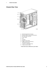
Power supply E. Serial B port knockout J. Alternate ICMB or external SCSI knockout C. AC input power connector D. I . ICMB or external SCSI knockout I /O ports* G. Intel® Entry Server Chassis SC5275-E User Guide 4 Fan F. Expansion slot covers H. Location to install padlock loop K. 1 Chassis Description Chassis Rear View A B C D E F TP00834 A. Chassis intrusion switch * Items shown may be different in your chassis. Alternate Serial B port knockout B.
Power supply E. Serial B port knockout J. Alternate ICMB or external SCSI knockout C. AC input power connector D. I . ICMB or external SCSI knockout I /O ports* G. Intel® Entry Server Chassis SC5275-E User Guide 4 Fan F. Expansion slot covers H. Location to install padlock loop K. 1 Chassis Description Chassis Rear View A B C D E F TP00834 A. Chassis intrusion switch * Items shown may be different in your chassis. Alternate Serial B port knockout B.
User Guide
Page 24
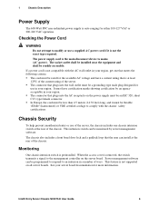
...or VDE certified cordage to mains (AC power). The chassis also includes a front bezel door lock and a padlock loop that plugs into the wall outlet must be monitored by an agency acceptable in a number of the chassis. Intel® Entry Server Chassis SC5275-E User Guide 6 The connector that the... user can be rated for either 100-127 VAC or 200-240 VAC operation. In Europe, the cord must be readily accessible. The power supply cord is preinstalled.
...or VDE certified cordage to mains (AC power). The chassis also includes a front bezel door lock and a padlock loop that plugs into the wall outlet must be monitored by an agency acceptable in a number of the chassis. Intel® Entry Server Chassis SC5275-E User Guide 6 The connector that the... user can be rated for either 100-127 VAC or 200-240 VAC operation. In Europe, the cord must be readily accessible. The power supply cord is preinstalled.

User Guide
Page 27
... replacing the front panel board (discussed in Chapter 4), it is necessary to chassis ground-any reason, observe these instructions and the instructions supplied with other regional product laws and regulations. Then unplug the AC power cord from the chassis or wall outlet. Intel® Entry Server Chassis SC5275-E User Guide 9 Follow these instructions, the UL listing will be void...
... replacing the front panel board (discussed in Chapter 4), it is necessary to chassis ground-any reason, observe these instructions and the instructions supplied with other regional product laws and regulations. Then unplug the AC power cord from the chassis or wall outlet. Intel® Entry Server Chassis SC5275-E User Guide 9 Follow these instructions, the UL listing will be void...

User Guide
Page 28
Only a technically qualified person should be present on power, telephone, and communication cables. There are present inside the power supply. Perform all procedures in place can be extremely sensitive to chassis groundany surface. For proper cooling and ...server before turning on the server. Turn off the AC power. 2 Setting Up the Chassis Warnings and Cautions These warnings and cautions apply whenever you place the server board on a conductive surface, the battery leads may be done by their edges. Intel® Entry Server Chassis SC5275...
Only a technically qualified person should be present on power, telephone, and communication cables. There are present inside the power supply. Perform all procedures in place can be extremely sensitive to chassis groundany surface. For proper cooling and ...server before turning on the server. Turn off the AC power. 2 Setting Up the Chassis Warnings and Cautions These warnings and cautions apply whenever you place the server board on a conductive surface, the battery leads may be done by their edges. Intel® Entry Server Chassis SC5275...

User Guide
Page 31
...the chassis wall and the lip of the chassis. Position one edge of the shield so that match the external I /O shield snaps into the opening near the power supply in place, and push it now. 2. If an EMI gasket was provided with your server board,...of the chassis. Install the shield from the inside of the server. The shield fits the rectangular opening until it is required by Electromagnetic Interference (EMI) regulations. 2 Setting Up the Chassis Install the I/O Shield ✏ NOTE An ATX 2.03-compliant I /O Shield TP00074 Intel® Entry Server Chassis SC5275-E User...
...the chassis wall and the lip of the chassis. Position one edge of the shield so that match the external I /O shield snaps into the opening near the power supply in place, and push it now. 2. If an EMI gasket was provided with your server board,...of the chassis. Install the shield from the inside of the server. The shield fits the rectangular opening until it is required by Electromagnetic Interference (EMI) regulations. 2 Setting Up the Chassis Install the I/O Shield ✏ NOTE An ATX 2.03-compliant I /O Shield TP00074 Intel® Entry Server Chassis SC5275-E User...

User Guide
Page 47
... present inside the power supply. servicing should integrate and configure the server. Warnings and Cautions These warnings and cautions apply whenever you must unplug the AC power cord from the chassis or wall outlet. 4. To remove power from server, you remove the...power button on the front panel DOES NOT turn off the server and disconnect the power cords, telecommunications systems, networks, and modems attached to chassis ground-any reason, observe these safety guidelines: 1. Turn off the AC power. Intel® Entry Server Chassis SC5275-E User Guide 29 Unplug the AC power...
... present inside the power supply. servicing should integrate and configure the server. Warnings and Cautions These warnings and cautions apply whenever you must unplug the AC power cord from the chassis or wall outlet. 4. To remove power from server, you remove the...power button on the front panel DOES NOT turn off the server and disconnect the power cords, telecommunications systems, networks, and modems attached to chassis ground-any reason, observe these safety guidelines: 1. Turn off the AC power. Intel® Entry Server Chassis SC5275-E User Guide 29 Unplug the AC power...

User Guide
Page 49
The power supply fan(s) are removing. Remove the left access cover. 2. Disconnect the cables from the chassis. Remove the two screws at the front of the hard drive bay cage and the two screws at the side of the cage. 6. It may ...be necessary to pry up the four nylon rivets that hold the fan in a Standard Drive Cage Intel® Entry Server Chassis SC5275-E User Guide 31 3 Maintaining Your Server Replacing Fans The chassis contains two replaceable system fans. Replacing a Front System Fan Standard Hard Drive Bay Cage The front system fan is not necessary...
The power supply fan(s) are removing. Remove the left access cover. 2. Disconnect the cables from the chassis. Remove the two screws at the front of the hard drive bay cage and the two screws at the side of the cage. 6. It may ...be necessary to pry up the four nylon rivets that hold the fan in a Standard Drive Cage Intel® Entry Server Chassis SC5275-E User Guide 31 3 Maintaining Your Server Replacing Fans The chassis contains two replaceable system fans. Replacing a Front System Fan Standard Hard Drive Bay Cage The front system fan is not necessary...

User Guide
Page 51
... the power supply. Disconnect all of the power cables inside of the chassis, two inside the chassis). 9. A A A A A A A. Insert the replacement power supply into the chassis. 8. Connect the A/C power to the server board and peripherals. 10. Insert and tighten the screws that hold the power supply the chassis (four at the back of the chassis. 6. Disconnect the A/C power from the chassis. 7. Replacing the AC Power Supply TP00068 Intel® Entry Server Chassis SC5275-E User...
... the power supply. Disconnect all of the power cables inside of the chassis, two inside the chassis). 9. A A A A A A A. Insert the replacement power supply into the chassis. 8. Connect the A/C power to the server board and peripherals. 10. Insert and tighten the screws that hold the power supply the chassis (four at the back of the chassis. 6. Disconnect the A/C power from the chassis. 7. Replacing the AC Power Supply TP00068 Intel® Entry Server Chassis SC5275-E User...

User Guide
Page 57
... Voltage Maximum Current +3.3 V 24 A +5.0 V 24 A +5 V Standby 2 A +12.0 43 A -12.0 V 0.5 A CAUTION Do not exceed a combined power output of 600 Watts. Exceeding a combined 179 Watts will overload the power subsystem and may cause the power supplies to overheat and malfunction. Intel® Entry Server Chassis SC5275-E User Guide 39 If you configure your system heavily, ensure that your configuration, see page...
... Voltage Maximum Current +3.3 V 24 A +5.0 V 24 A +5 V Standby 2 A +12.0 43 A -12.0 V 0.5 A CAUTION Do not exceed a combined power output of 600 Watts. Exceeding a combined 179 Watts will overload the power subsystem and may cause the power supplies to overheat and malfunction. Intel® Entry Server Chassis SC5275-E User Guide 39 If you configure your system heavily, ensure that your configuration, see page...

User Guide
Page 61
... V +12 V -12 V Total Current 5 V Standby Intel® Entry Server Chassis SC5275-E User Guide 43 Worksheet, Calculating DC Power Usage Table 6. Equipment Log and Worksheets Current Usage Calculating Power Usage The total combined wattage for your configuration must be less ...than the wattage rating for your configuration. Use the two worksheets in boards and peripherals, see your vendor documents. For current and voltage requirements of add-in this section to calculate the total used by your power supply...
... V +12 V -12 V Total Current 5 V Standby Intel® Entry Server Chassis SC5275-E User Guide 43 Worksheet, Calculating DC Power Usage Table 6. Equipment Log and Worksheets Current Usage Calculating Power Usage The total combined wattage for your configuration must be less ...than the wattage rating for your configuration. Use the two worksheets in boards and peripherals, see your vendor documents. For current and voltage requirements of add-in this section to calculate the total used by your power supply...

User Guide
Page 68
... the following URL: http://channel.intel.com/go/serverbuilder If you must be UL recognized or UL listed accessory and TUV or VDE licensed. Add-in which it is provided with power supply and fans)UL listed. Intel® Entry Server Chassis SC5275-E User Guide 50 Any add-...in boards containing external power connectors and/or lithium batteries must have the appropriate telecommunications, safety, and EMC...
... the following URL: http://channel.intel.com/go/serverbuilder If you must be UL recognized or UL listed accessory and TUV or VDE licensed. Add-in which it is provided with power supply and fans)UL listed. Intel® Entry Server Chassis SC5275-E User Guide 50 Any add-...in boards containing external power connectors and/or lithium batteries must have the appropriate telecommunications, safety, and EMC...
