User Guide
Page 1
Intel® Entry Server Chassis SC5275-E User Guide A Guide for Technically Qualified Assemblers of Intel® Identified Subassemblies/Products Order Number: C50277-001
Intel® Entry Server Chassis SC5275-E User Guide A Guide for Technically Qualified Assemblers of Intel® Identified Subassemblies/Products Order Number: C50277-001
User Guide
Page 2
... estoppel or otherwise, to specifications and product descriptions at any features or instructions marked "reserved" or "undefined." Intel® Entry Server Chassis SC5275-E User Guide ii Intel may occur. Designers must not rely on products in connection with Intel® products. This document contains information on the absence or characteristics of any time, without notice. Copyright ©...
... estoppel or otherwise, to specifications and product descriptions at any features or instructions marked "reserved" or "undefined." Intel® Entry Server Chassis SC5275-E User Guide ii Intel may occur. Designers must not rely on products in connection with Intel® products. This document contains information on the absence or characteristics of any time, without notice. Copyright ©...

User Guide
Page 3
... product, and product diagrams to http://support.intel.com/support/motherboards/server/chassis/SC5275E. This manual is compatible with the following Intel® Server Boards: Intel® Server Board SE7525GP2 Intel® Server Board SE7320SP2 Intel® Server Board SE7520BD2 For information about which items have been tested and can be used with your server. Intel® Entry Server Chassis SC5275-E User Guide iii Chapter 2 provides instructions...
... product, and product diagrams to http://support.intel.com/support/motherboards/server/chassis/SC5275E. This manual is compatible with the following Intel® Server Boards: Intel® Server Board SE7525GP2 Intel® Server Board SE7320SP2 Intel® Server Board SE7520BD2 For information about which items have been tested and can be used with your server. Intel® Entry Server Chassis SC5275-E User Guide iii Chapter 2 provides instructions...

User Guide
Page 4
... need to spares, parts, and config guide) http://www.support.intel/com/support/mothterboards/server/S C5275E/tested_hwos.htm http://support.intel.com/support/motherboards/server/SC5275 E/os.htm http://www.support.intel/com/support/mothterboards/server/S C5275E/chassis_list.htm http://developer.intel.com/design/servers/smarttool/index.htm Intel® Entry Server Chassis SC5275-E User Guide iv Preface Additional Information and Software If you...
... need to spares, parts, and config guide) http://www.support.intel/com/support/mothterboards/server/S C5275E/tested_hwos.htm http://support.intel.com/support/motherboards/server/SC5275 E/os.htm http://www.support.intel/com/support/mothterboards/server/S C5275E/chassis_list.htm http://developer.intel.com/design/servers/smarttool/index.htm Intel® Entry Server Chassis SC5275-E User Guide iv Preface Additional Information and Software If you...

User Guide
Page 5
..., or remove any other parts. This is not available, provide some ESD protection by wearing an antistatic wrist Intel® Entry Server Chassis SC5275-E User Guide v Turn off the system AC power. Use only the described, regulated components specified in this guide. Intended Uses This product was evaluated as ...
..., or remove any other parts. This is not available, provide some ESD protection by wearing an antistatic wrist Intel® Entry Server Chassis SC5275-E User Guide v Turn off the system AC power. Use only the described, regulated components specified in this guide. Intended Uses This product was evaluated as ...

User Guide
Page 6
...Turn off the system by that slips over any surface. Intel® Entry Server Chassis SC5275-E User Guide vi The socket outlet that you remove the chassis covers to access the inside the jumper, causing intermittent problems with your server when handling parts. SAFETY STEPS: Whenever you can damage... power button on the Resource CD and/or at http://support.intel.com/support/motherboards/server/safecert.htm. The power cord(s) is not the exact type required. See also Intel Server Boards and Server Chassis Safety Information on the system does not turn off all AC power...
...Turn off the system by that slips over any surface. Intel® Entry Server Chassis SC5275-E User Guide vi The socket outlet that you remove the chassis covers to access the inside the jumper, causing intermittent problems with your server when handling parts. SAFETY STEPS: Whenever you can damage... power button on the Resource CD and/or at http://support.intel.com/support/motherboards/server/safecert.htm. The power cord(s) is not the exact type required. See also Intel Server Boards and Server Chassis Safety Information on the system does not turn off all AC power...

User Guide
Page 7
... tools or parts inside the system. 5. Consider wearing protective gloves. Dispose of explosion if the battery is incorrectly replaced. und Sicherheitshinweise in a typical office environment. Intel® Entry Server Chassis SC5275-E User Guide vii To do this: 1. Connect all screws from strong electromagnetic fields produced by wearing an antistatic wrist strap attached to...
... tools or parts inside the system. 5. Consider wearing protective gloves. Dispose of explosion if the battery is incorrectly replaced. und Sicherheitshinweise in a typical office environment. Intel® Entry Server Chassis SC5275-E User Guide vii To do this: 1. Connect all screws from strong electromagnetic fields produced by wearing an antistatic wrist strap attached to...

User Guide
Page 15
... 20 Connect Cables to the Server Board 23 Installing an Add-in Board ...24 Install the Front Bezel ...26 Install the Access Cover...27 3 Maintaining Your Server 29 Tools and Supplies Needed 29 Safety: Before You Remove the Access Cover(s 29 Warnings and Cautions...29 Replacing Fans ...31 Intel® Entry Server Chassis SC5275-E User Guide xv
... 20 Connect Cables to the Server Board 23 Installing an Add-in Board ...24 Install the Front Bezel ...26 Install the Access Cover...27 3 Maintaining Your Server 29 Tools and Supplies Needed 29 Safety: Before You Remove the Access Cover(s 29 Warnings and Cautions...29 Replacing Fans ...31 Intel® Entry Server Chassis SC5275-E User Guide xv

User Guide
Page 16
... to Obtain Warranty Service 55 Telephone Support...55 Returning a Defective Product 55 Figures Figure 1. Mechanical Locks ...7 Figure 3. Screw Description...1 Figure 2. Installing the I/O Shield 13 Intel® Entry Server Chassis SC5275-E User Guide xvi Contents Replacing a Front System Fan 31 Replacing a Rear System Fan 32 Replacing the Power Supply 33 Replacing the Front Panel Board 34...
... to Obtain Warranty Service 55 Telephone Support...55 Returning a Defective Product 55 Figures Figure 1. Mechanical Locks ...7 Figure 3. Screw Description...1 Figure 2. Installing the I/O Shield 13 Intel® Entry Server Chassis SC5275-E User Guide xvi Contents Replacing a Front System Fan 31 Replacing a Rear System Fan 32 Replacing the Power Supply 33 Replacing the Front Panel Board 34...

User Guide
Page 17
... ...3 Accessories and Order Codes 5 Power Supply System Output Capability 39 Environmental Specifications 40 Power Usage Worksheet 1 43 Power Usage Worksheet 2 44 Product Certification Markings 46 Intel® Entry Server Chassis SC5275-E User Guide xvii Front Panel Board Access 34 Figure 20. Table 2. Table 5. Contents Figure 6. Table 3. Installing the Hard Drive Bay Cage 22 Figure 14...
... ...3 Accessories and Order Codes 5 Power Supply System Output Capability 39 Environmental Specifications 40 Power Usage Worksheet 1 43 Power Usage Worksheet 2 44 Product Certification Markings 46 Intel® Entry Server Chassis SC5275-E User Guide xvii Front Panel Board Access 34 Figure 20. Table 2. Table 5. Contents Figure 6. Table 3. Installing the Hard Drive Bay Cage 22 Figure 14...

User Guide
Page 19
..., and two brackets for up to six 3.5-inch hard disk drives. Cooling Two system fans inside the chassis and one power supply fan provide cooling and airflow. Intel® Entry Server Chassis SC5275-E User Guide 1 Flat head 6-32 x 5mm [.200] B. Expansion Slot Up to seven expansion slots...swap hard drive bay (SCSI hot-swap hard drive bay not included). The cage is not externally accessible. 1 Chassis Description 1 Chassis Description Kit Contents The chassis subassembly kit includes this product guide and a box that are externally accessible, designed to hold up to five 1-...
..., and two brackets for up to six 3.5-inch hard disk drives. Cooling Two system fans inside the chassis and one power supply fan provide cooling and airflow. Intel® Entry Server Chassis SC5275-E User Guide 1 Flat head 6-32 x 5mm [.200] B. Expansion Slot Up to seven expansion slots...swap hard drive bay (SCSI hot-swap hard drive bay not included). The cage is not externally accessible. 1 Chassis Description 1 Chassis Description Kit Contents The chassis subassembly kit includes this product guide and a box that are externally accessible, designed to hold up to five 1-...
User Guide
Page 20
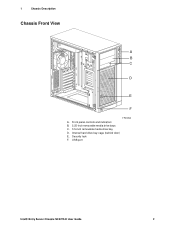
1 Chassis Description Chassis Front View A B C D E F TP00053 A. Security lock F. USB port Intel® Entry Server Chassis SC5275-E User Guide 2 Internal hard drive bay cage (behind door) E. Front panel controls and indicators B. 5.25-inch removable media drive bays C. 3.5-inch removable media drive bay D.
1 Chassis Description Chassis Front View A B C D E F TP00053 A. Security lock F. USB port Intel® Entry Server Chassis SC5275-E User Guide 2 Internal hard drive bay cage (behind door) E. Front panel controls and indicators B. 5.25-inch removable media drive bays C. 3.5-inch removable media drive bay D.
User Guide
Page 21
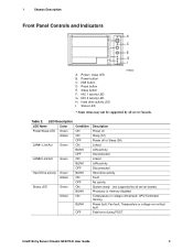
Status LED TP00080 * Some items may not be supported by all server boards. CPU/Terminator missing Power fault; Power button C. Reset button E. NIC 1 activity LED G. Hard drive activity LED I A.... supported by all server boards) Processor or memory disabled Temperature or voltage critical fault; NIC 2 activity LED H. Table 2. 1 Chassis Description Front Panel Controls and Indicators A B C D E F G H I . Power / sleep LED B. Fan fault; Temperature or voltage non-critical fault Fatal error during POST Intel® Entry Server Chassis SC5275-E User Guide 3...
Status LED TP00080 * Some items may not be supported by all server boards. CPU/Terminator missing Power fault; Power button C. Reset button E. NIC 1 activity LED G. Hard drive activity LED I A.... supported by all server boards) Processor or memory disabled Temperature or voltage critical fault; NIC 2 activity LED H. Table 2. 1 Chassis Description Front Panel Controls and Indicators A B C D E F G H I . Power / sleep LED B. Fan fault; Temperature or voltage non-critical fault Fatal error during POST Intel® Entry Server Chassis SC5275-E User Guide 3...
User Guide
Page 22
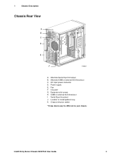
Power supply E. ICMB or external SCSI knockout I /O ports* G. Location to install padlock loop K. Intel® Entry Server Chassis SC5275-E User Guide 4 Fan F. 1 Chassis Description Chassis Rear View A B C D E F TP00834 A. Alternate ICMB or external SCSI knockout C. I . Serial B port knockout J. Chassis intrusion switch * Items shown may be different in your chassis. AC input power connector D. Expansion slot covers H. Alternate Serial B port knockout B.
Power supply E. ICMB or external SCSI knockout I /O ports* G. Location to install padlock loop K. Intel® Entry Server Chassis SC5275-E User Guide 4 Fan F. 1 Chassis Description Chassis Rear View A B C D E F TP00834 A. Alternate ICMB or external SCSI knockout C. I . Serial B port knockout J. Chassis intrusion switch * Items shown may be different in your chassis. AC input power connector D. Expansion slot covers H. Alternate Serial B port knockout B.

User Guide
Page 23
... up to six 3.5-inch SCSI hot-swap hard drives. Five bays are included with all server boards. Order Code AXX6SCSIDB AXX6SATADB APT2WKTCOOLKIT AXX2ICMBKIT AXXEXTSCSICBL Intel® Entry Server Chassis SC5275-E User Guide 5 The drives are installed into a removable hard drive bay cage that consume up to ensure proper hard drive cooling. Accessories and Order Codes ...
... up to six 3.5-inch SCSI hot-swap hard drives. Five bays are included with all server boards. Order Code AXX6SCSIDB AXX6SATADB APT2WKTCOOLKIT AXX2ICMBKIT AXXEXTSCSICBL Intel® Entry Server Chassis SC5275-E User Guide 5 The drives are installed into a removable hard drive bay cage that consume up to ensure proper hard drive cooling. Accessories and Order Codes ...
User Guide
Page 24
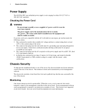
... sheet C13, type female connector. Monitoring One chassis intrusion switch is the main disconnect device to comply with the AC wall outlet in your region, get one chassis intrusion switch at the rear of the chassis. Intel® Entry Server Chassis SC5275-E User Guide 6 If a power cord is... at the rear of the chassis. See your region. The connector that meets the following criteria:...
... sheet C13, type female connector. Monitoring One chassis intrusion switch is the main disconnect device to comply with the AC wall outlet in your region, get one chassis intrusion switch at the rear of the chassis. Intel® Entry Server Chassis SC5275-E User Guide 6 If a power cord is... at the rear of the chassis. See your region. The connector that meets the following criteria:...
User Guide
Page 25
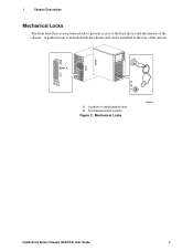
Front bezel locked position Figure 2. Location to the hard drives and the interior of the chassis. A B A. A padlock loop is included with the chassis and can be installed at the rear of the chassis. 1 Chassis Description Mechanical Locks The front bezel has a two-position lock to prevent access to install padlock loop B. Mechanical Locks TP00055 Intel® Entry Server Chassis SC5275-E User Guide 7
Front bezel locked position Figure 2. Location to the hard drives and the interior of the chassis. A B A. A padlock loop is included with the chassis and can be installed at the rear of the chassis. 1 Chassis Description Mechanical Locks The front bezel has a two-position lock to prevent access to install padlock loop B. Mechanical Locks TP00055 Intel® Entry Server Chassis SC5275-E User Guide 7

User Guide
Page 27
Follow these guidelines to meet and maintain safety and product regulatory requirements when integrating this assembly. Turn off all peripheral devices connected to the server. Intel® Entry Server Chassis SC5275-E User Guide 9 Tools and Supplies Needed Phillips (cross head) screwdriver (#2 bit) Small flathead screwdriver Antistatic wrist strap (recommended) Installation Safety Instructions Only technically qualified personnel ...
Follow these guidelines to meet and maintain safety and product regulatory requirements when integrating this assembly. Turn off all peripheral devices connected to the server. Intel® Entry Server Chassis SC5275-E User Guide 9 Tools and Supplies Needed Phillips (cross head) screwdriver (#2 bit) Small flathead screwdriver Antistatic wrist strap (recommended) Installation Safety Instructions Only technically qualified personnel ...

User Guide
Page 28
...grounded, static free surface. servicing should integrate and configure the server. 2 Setting Up the Chassis Warnings and Cautions These warnings and cautions apply whenever you place the server board on your server when handling parts. If one is not available, provide ...NOT turn off the server and disconnect the power cords, telecommunications systems, networks, and modems attached to chassis groundany surface. Always handle boards carefully. Intel® Entry Server Chassis SC5275-E User Guide 10 WARNINGS The power button on the server. Otherwise, personal injury...
...grounded, static free surface. servicing should integrate and configure the server. 2 Setting Up the Chassis Warnings and Cautions These warnings and cautions apply whenever you place the server board on your server when handling parts. If one is not available, provide ...NOT turn off the server and disconnect the power cords, telecommunications systems, networks, and modems attached to chassis groundany surface. Always handle boards carefully. Intel® Entry Server Chassis SC5275-E User Guide 10 WARNINGS The power button on the server. Otherwise, personal injury...
User Guide
Page 29
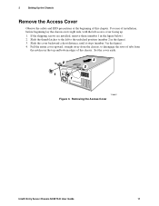
... cover facing up. 1. Pull the entire cover upward, straight away from the chassis, to the unlocked position (number 2 in the top and bottom edges of this chapter. Removing the Access Cover Intel® Entry Server Chassis SC5275-E User Guide 11 Set the cover aside. 2 1 1 3 2 TP00057 Figure... 3. For ease of installation, before beginning lay the chassis on its right side, with the left to disengage the rows ...
... cover facing up. 1. Pull the entire cover upward, straight away from the chassis, to the unlocked position (number 2 in the top and bottom edges of this chapter. Removing the Access Cover Intel® Entry Server Chassis SC5275-E User Guide 11 Set the cover aside. 2 1 1 3 2 TP00057 Figure... 3. For ease of installation, before beginning lay the chassis on its right side, with the left to disengage the rows ...