
User Guide
Page 15
... 20 Connect Cables to the Server Board 23 Installing an Add-in Board ...24 Install the Front Bezel ...26 Install the Access Cover...27 3 Maintaining Your Server 29 Tools and Supplies Needed 29 Safety: Before You Remove the Access Cover(s 29 Warnings and Cautions...29 Replacing Fans ...31 Intel® Entry Server Chassis SC5275-E User Guide xv
... 20 Connect Cables to the Server Board 23 Installing an Add-in Board ...24 Install the Front Bezel ...26 Install the Access Cover...27 3 Maintaining Your Server 29 Tools and Supplies Needed 29 Safety: Before You Remove the Access Cover(s 29 Warnings and Cautions...29 Replacing Fans ...31 Intel® Entry Server Chassis SC5275-E User Guide xv

User Guide
Page 17
... 8. Installing the Hard Drive Bay Cage 22 Figure 14. Removing the Front Panel Board 34 Figure 21. Feature Summary ...1 LED Description ...3 Accessories and Order Codes 5 Power Supply System Output Capability 39 Environmental Specifications 40 Power Usage Worksheet 1 43 Power Usage Worksheet 2 44 Product Certification Markings 46 Intel® Entry Server Chassis SC5275-E User Guide xvii Removing...
... 8. Installing the Hard Drive Bay Cage 22 Figure 14. Removing the Front Panel Board 34 Figure 21. Feature Summary ...1 LED Description ...3 Accessories and Order Codes 5 Power Supply System Output Capability 39 Environmental Specifications 40 Power Usage Worksheet 1 43 Power Usage Worksheet 2 44 Product Certification Markings 46 Intel® Entry Server Chassis SC5275-E User Guide xvii Removing...

User Guide
Page 19
... two brackets for up to six 3.5-inch hard disk drives. Hex head 6-32 x 6mm [.256] Figure 1. The cage is not externally accessible. Intel® Entry Server Chassis SC5275-E User Guide 1 A hard drive bay cage designed to hold half-height standard removable media devices. Flat head M3 x 5mm [.200] C. unused expansion slots must have a slot cover Covers...
... two brackets for up to six 3.5-inch hard disk drives. Hex head 6-32 x 6mm [.256] Figure 1. The cage is not externally accessible. Intel® Entry Server Chassis SC5275-E User Guide 1 A hard drive bay cage designed to hold half-height standard removable media devices. Flat head M3 x 5mm [.200] C. unused expansion slots must have a slot cover Covers...
User Guide
Page 20
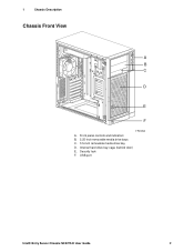
Internal hard drive bay cage (behind door) E. USB port Intel® Entry Server Chassis SC5275-E User Guide 2 Security lock F. Front panel controls and indicators B. 5.25-inch removable media drive bays C. 3.5-inch removable media drive bay D. 1 Chassis Description Chassis Front View A B C D E F TP00053 A.
Internal hard drive bay cage (behind door) E. USB port Intel® Entry Server Chassis SC5275-E User Guide 2 Security lock F. Front panel controls and indicators B. 5.25-inch removable media drive bays C. 3.5-inch removable media drive bay D. 1 Chassis Description Chassis Front View A B C D E F TP00053 A.

User Guide
Page 23
... not externally accessible. Order Code AXX6SCSIDB AXX6SATADB APT2WKTCOOLKIT AXX2ICMBKIT AXXEXTSCSICBL Intel® Entry Server Chassis SC5275-E User Guide 5 You can install up to 18 Watts of spares and accessories, see http://www.intel.com/go/serverbuilder Table 3. 1 Chassis Description Peripherals 5.25-inch Removable Media Drive Bays The upper bays are designed for use with the upgrade kit. Accessories and...
... not externally accessible. Order Code AXX6SCSIDB AXX6SATADB APT2WKTCOOLKIT AXX2ICMBKIT AXXEXTSCSICBL Intel® Entry Server Chassis SC5275-E User Guide 5 You can install up to 18 Watts of spares and accessories, see http://www.intel.com/go/serverbuilder Table 3. 1 Chassis Description Peripherals 5.25-inch Removable Media Drive Bays The upper bays are designed for use with the upgrade kit. Accessories and...

User Guide
Page 33
Connect the data and power cables to the chassis. Tighten the screws firmly. 10. Intel® Entry Server Chassis SC5275-E User Guide 15 Note that only two screws are required at the left side of the drive align with two screws. Installing a Floppy Drive... depends on: The number supported by the bus on your server board The number of physical drive bays available The combination of SCSI and IDE devices The amount of the chassis with the threaded holes in the chassis frame. 9. Slide the drive into the chassis. B TP00060 Figure 7. When properly positioned, the holes in...
Connect the data and power cables to the chassis. Tighten the screws firmly. 10. Intel® Entry Server Chassis SC5275-E User Guide 15 Note that only two screws are required at the left side of the drive align with two screws. Installing a Floppy Drive... depends on: The number supported by the bus on your server board The number of physical drive bays available The combination of SCSI and IDE devices The amount of the chassis with the threaded holes in the chassis frame. 9. Slide the drive into the chassis. B TP00060 Figure 7. When properly positioned, the holes in...

User Guide
Page 34
If only one drive is present. Removing EMI Shields Intel® Entry Server Chassis SC5275-E User Guide 16 Save the shield in the bays or EMI shields covering the bays. Remove the plastic filler panel from the board connector if a cable is installed, it straight out. When you install a drive, save the shield ... by using the finger-slots to grasp it and pull it should later remove the drive and not reinstall one in the same bay. 1. 2 Setting Up the Chassis IDE Requirements If no drives are both protected by having drives installed in case you later remove the peripheral. 2.
If only one drive is present. Removing EMI Shields Intel® Entry Server Chassis SC5275-E User Guide 16 Save the shield in the bays or EMI shields covering the bays. Remove the plastic filler panel from the board connector if a cable is installed, it straight out. When you install a drive, save the shield ... by using the finger-slots to grasp it and pull it should later remove the drive and not reinstall one in the same bay. 1. 2 Setting Up the Chassis IDE Requirements If no drives are both protected by having drives installed in case you later remove the peripheral. 2.

User Guide
Page 36
Connect the data and power cables to attach the device at the front of the chassis. 9. Installing a Removable Media Device Intel® Entry Server Chassis SC5275-E User Guide 18 2 Setting Up the Chassis 7. Position the drive so the slide rails engage in only one way. The connectors are flush with the chassis. 8. Use two screws for each slide rail to the drive. TP00065 Figure 10. Push the drive into the bay until the slide rails are keyed and can be inserted in the chassis bay guide rails.
Connect the data and power cables to attach the device at the front of the chassis. 9. Installing a Removable Media Device Intel® Entry Server Chassis SC5275-E User Guide 18 2 Setting Up the Chassis 7. Position the drive so the slide rails engage in only one way. The connectors are flush with the chassis. 8. Use two screws for each slide rail to the drive. TP00065 Figure 10. Push the drive into the bay until the slide rails are keyed and can be inserted in the chassis bay guide rails.

User Guide
Page 38
... jumpers or switches on the front of the chassis. For proper cooling, always install drives into the four center bays first ✏ NOTE The drive bay cage can only be needed for hard drives. Record the drive model and serial numbers in your equipment log. 5. Intel® Entry Server Chassis SC5275-E User Guide 20 Two screws are at...
... jumpers or switches on the front of the chassis. For proper cooling, always install drives into the four center bays first ✏ NOTE The drive bay cage can only be needed for hard drives. Record the drive model and serial numbers in your equipment log. 5. Intel® Entry Server Chassis SC5275-E User Guide 20 Two screws are at...

User Guide
Page 40
Insert and tighten the four screws removed in Step 1. 12. Attach data and power cables to the drive(s). Installing the Hard Drive Bay Cage Intel® Entry Server Chassis SC5275-E User Guide 22 A B TP00066 A. Figure 13. Data and power cables B. Point toward the top of chassis. Screw tabs. 2 Setting Up the Chassis 10. After all drives are installed into the cage, slide the cage into the chassis, making sure the arrow and the screw tabs point toward top of the chassis. 11.
Insert and tighten the four screws removed in Step 1. 12. Attach data and power cables to the drive(s). Installing the Hard Drive Bay Cage Intel® Entry Server Chassis SC5275-E User Guide 22 A B TP00066 A. Figure 13. Data and power cables B. Point toward the top of chassis. Screw tabs. 2 Setting Up the Chassis 10. After all drives are installed into the cage, slide the cage into the chassis, making sure the arrow and the screw tabs point toward top of the chassis. 11.

User Guide
Page 49
...It is located inside the hard drive bay cage. Disconnect the cables from the chassis. Slide the cage from all hard drives. 5. It may be necessary to pry up the four nylon rivets that hold the fan in a Standard Drive Cage Intel® Entry Server Chassis SC5275-E User Guide 31 Use a flat-head...the hard drive bay cage and the two screws at the side of the cage. 6. Replacing a Front System Fan Standard Hard Drive Bay Cage The front system fan is not necessary to remove the hard drives from the server board. 4. 3 Maintaining Your Server Replacing Fans The chassis contains two ...
...It is located inside the hard drive bay cage. Disconnect the cables from the chassis. Slide the cage from all hard drives. 5. It may be necessary to pry up the four nylon rivets that hold the fan in a Standard Drive Cage Intel® Entry Server Chassis SC5275-E User Guide 31 Use a flat-head...the hard drive bay cage and the two screws at the side of the cage. 6. Replacing a Front System Fan Standard Hard Drive Bay Cage The front system fan is not necessary to remove the hard drives from the server board. 4. 3 Maintaining Your Server Replacing Fans The chassis contains two ...

User Guide
Page 50
... fan opening . Replace the access cover. Remove the fan from the server board. 3. Intel® Entry Server Chassis SC5275-E User Guide 32 This means the label should face the server board. 7. Connect the fan cable to the hard drive bay cage. 11. No tools are necessary; the fan snaps in and ...out of the chassis. Attach the finger guard with the rivets to...
... fan opening . Replace the access cover. Remove the fan from the server board. 3. Intel® Entry Server Chassis SC5275-E User Guide 32 This means the label should face the server board. 7. Connect the fan cable to the hard drive bay cage. 11. No tools are necessary; the fan snaps in and ...out of the chassis. Attach the finger guard with the rivets to...