
User Guide
Page 15
...Cover...11 Remove the Front Bezel ...12 Install the I/O Shield ...13 Install the Server Board Standoffs and Bumpers 14 Install a 3.5-inch Floppy Drive 14 Peripheral Drives...15 Device Installation Considerations 15 Installing a 5.25-inch Removable Media Device 16 Install the Server Board...Server Board 23 Installing an Add-in Board ...24 Install the Front Bezel ...26 Install the Access Cover...27 3 Maintaining Your Server 29 Tools and Supplies Needed 29 Safety: Before You Remove the Access Cover(s 29 Warnings and Cautions...29 Replacing Fans ...31 Intel® Entry Server Chassis SC5275...
...Cover...11 Remove the Front Bezel ...12 Install the I/O Shield ...13 Install the Server Board Standoffs and Bumpers 14 Install a 3.5-inch Floppy Drive 14 Peripheral Drives...15 Device Installation Considerations 15 Installing a 5.25-inch Removable Media Device 16 Install the Server Board...Server Board 23 Installing an Add-in Board ...24 Install the Front Bezel ...26 Install the Access Cover...27 3 Maintaining Your Server 29 Tools and Supplies Needed 29 Safety: Before You Remove the Access Cover(s 29 Warnings and Cautions...29 Replacing Fans ...31 Intel® Entry Server Chassis SC5275...

User Guide
Page 16
Removing the Front Bezel 12 Figure 5. Installing the I/O Shield 13 Intel® Entry Server Chassis SC5275-E User Guide xvi Class A Compliance 45 Certifications / Registrations / Declarations 46 Product Regulatory Compliance Markings 46 Electromagnetic ...; Chassis Subassembly Products 53 Extent of Limited Warranty...53 Warranty Limitations and Exclusions 54 Limitations of Liability 54 How to Obtain Warranty Service 55 Telephone Support...55 Returning a Defective Product 55 Figures Figure 1. Screw Description...1 Figure 2. Removing the Access Cover 11 Figure 4. Contents...
Removing the Front Bezel 12 Figure 5. Installing the I/O Shield 13 Intel® Entry Server Chassis SC5275-E User Guide xvi Class A Compliance 45 Certifications / Registrations / Declarations 46 Product Regulatory Compliance Markings 46 Electromagnetic ...; Chassis Subassembly Products 53 Extent of Limited Warranty...53 Warranty Limitations and Exclusions 54 Limitations of Liability 54 How to Obtain Warranty Service 55 Telephone Support...55 Returning a Defective Product 55 Figures Figure 1. Screw Description...1 Figure 2. Removing the Access Cover 11 Figure 4. Contents...

User Guide
Page 17
... ...3 Accessories and Order Codes 5 Power Supply System Output Capability 39 Environmental Specifications 40 Power Usage Worksheet 1 43 Power Usage Worksheet 2 44 Product Certification Markings 46 Intel® Entry Server Chassis SC5275-E User Guide xvii Replacing the AC Power Supply 33 Figure 19. Table 7. Installing a Floppy Drive 15 Figure 8. Removing a Drive Cage 19 Figure 12. Table...
... ...3 Accessories and Order Codes 5 Power Supply System Output Capability 39 Environmental Specifications 40 Power Usage Worksheet 1 43 Power Usage Worksheet 2 44 Product Certification Markings 46 Intel® Entry Server Chassis SC5275-E User Guide xvii Replacing the AC Power Supply 33 Figure 19. Table 7. Installing a Floppy Drive 15 Figure 8. Removing a Drive Cage 19 Figure 12. Table...
User Guide
Page 29
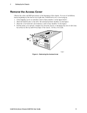
...shipping screws are installed, remove them (number 1 in the figure). 4. 2 Setting Up the Chassis Remove the Access Cover Observe the safety and ESD precautions at the beginning of the chassis. Set the cover aside. 2 1 1 3 2 TP00057 Figure 3. For ease of installation,... before beginning lay the chassis on its right side, with the left to disengage the rows of tabs from the notches in the figure). 3. Slide the cover backward a short distance, until it stops (number 3 in the figure below). 2. Removing the Access Cover Intel® Entry Server Chassis SC5275-E User Guide 11
...shipping screws are installed, remove them (number 1 in the figure). 4. 2 Setting Up the Chassis Remove the Access Cover Observe the safety and ESD precautions at the beginning of the chassis. Set the cover aside. 2 1 1 3 2 TP00057 Figure 3. For ease of installation,... before beginning lay the chassis on its right side, with the left to disengage the rows of tabs from the notches in the figure). 3. Slide the cover backward a short distance, until it stops (number 3 in the figure below). 2. Removing the Access Cover Intel® Entry Server Chassis SC5275-E User Guide 11

User Guide
Page 37
Removing a Drive Cage 3. Intel® Entry Server Chassis SC5275-E User Guide 19 These instructions will guide you through the I /O connector end first. Insert screws loosely through the server board mounting holes and into the chassis I /O shield at the center of the chassis. 5. For additional information, read and follow the... front of the chassis. Attach the board to push the cage out from the inside of the chassis. 6. You may need to the two snap stand-offs at the side of the chassis. TP00062 Figure 11. 2 Setting Up the Chassis Install the Server Board 1. Remove ...
Removing a Drive Cage 3. Intel® Entry Server Chassis SC5275-E User Guide 19 These instructions will guide you through the I /O connector end first. Insert screws loosely through the server board mounting holes and into the chassis I /O shield at the center of the chassis. 5. For additional information, read and follow the... front of the chassis. Attach the board to push the cage out from the inside of the chassis. 6. You may need to the two snap stand-offs at the side of the chassis. TP00062 Figure 11. 2 Setting Up the Chassis Install the Server Board 1. Remove ...

User Guide
Page 40
Insert and tighten the four screws removed in Step 1. 12. A B TP00066 A. Figure 13. Attach data and power cables to the drive(s). Installing the Hard Drive Bay Cage Intel® Entry Server Chassis SC5275-E User Guide 22 After all drives are installed into the cage, slide the cage into the chassis, making sure the arrow and the screw tabs point toward top of the chassis. 11. Screw tabs. 2 Setting Up the Chassis 10. Data and power cables B. Point toward the top of chassis.
Insert and tighten the four screws removed in Step 1. 12. A B TP00066 A. Figure 13. Attach data and power cables to the drive(s). Installing the Hard Drive Bay Cage Intel® Entry Server Chassis SC5275-E User Guide 22 After all drives are installed into the cage, slide the cage into the chassis, making sure the arrow and the screw tabs point toward top of the chassis. 11. Screw tabs. 2 Setting Up the Chassis 10. Data and power cables B. Point toward the top of chassis.

User Guide
Page 50
...14. No tools are necessary; Place the new fan into the bracket. Connect the fan cable to the hard drive bay cage. 11. Intel® Entry Server Chassis SC5275-E User Guide 32 Remove the finger guard from the corners. 5. Replace the access cover. Disconnect the fan cable from the bracket. .... 6. Make sure the fan opening . This means the label should face the server board. 10. Replace the access cover. Remove the fan from the server board. 3. the fan snaps in and out of the chassis. Replacing a Rear System Fan 1. Remove the left access cover. 2. Slide the...
...14. No tools are necessary; Place the new fan into the bracket. Connect the fan cable to the hard drive bay cage. 11. Intel® Entry Server Chassis SC5275-E User Guide 32 Remove the finger guard from the corners. 5. Replace the access cover. Disconnect the fan cable from the bracket. .... 6. Make sure the fan opening . This means the label should face the server board. 10. Replace the access cover. Remove the fan from the server board. 3. the fan snaps in and out of the chassis. Replacing a Rear System Fan 1. Remove the left access cover. 2. Slide the...

User Guide
Page 51
... 3. Remove the power supply from the power supply. 2. Insert the replacement power supply into the chassis. 8. Replacing the AC Power Supply TP00068 Intel® Entry Server Chassis SC5275-E User Guide 33 There are present inside the power supply. servicing should be done by technically qualified...power supply to the bottom inside of the chassis, two inside the chassis. 4. Replace the access cover. 11. Disconnect all of the chassis. 5. Remove the two screws holding the front of the power supply to the back of the power cables inside the chassis). 9. A A A A A A A....
... 3. Remove the power supply from the power supply. 2. Insert the replacement power supply into the chassis. 8. Replacing the AC Power Supply TP00068 Intel® Entry Server Chassis SC5275-E User Guide 33 There are present inside the power supply. servicing should be done by technically qualified...power supply to the bottom inside of the chassis, two inside the chassis. 4. Replace the access cover. 11. Disconnect all of the chassis. 5. Remove the two screws holding the front of the power supply to the back of the power cables inside the chassis). 9. A A A A A A A....

User Guide
Page 53
... panel board cable through the front panel opening and attach it to ensure the cable pins line up correctly. Intel® Entry Server Chassis SC5275-E User Guide 35 Attaching the Front Panel Cable 9. Inserting the Front Panel Board 11. Replace the left access cover. Attach the cable before installing the new front panel board into the...
... panel board cable through the front panel opening and attach it to ensure the cable pins line up correctly. Intel® Entry Server Chassis SC5275-E User Guide 35 Attaching the Front Panel Cable 9. Inserting the Front Panel Board 11. Replace the left access cover. Attach the cable before installing the new front panel board into the...

User Guide
Page 54
...to over the USB port at the front of the chassis. 5. Slide the USB cable out through the hole at the front of the chassis to the server board. A 3 1 2 1 TP00079 Figure 23.... Install the bracket over the add-in board retention bracket as shown in board retention bracket at the front of the chassis. 13....the hole at the front of the chassis to create a gap between the top of the chassis, indicated by the letter A in cards. 14. Intel® Entry Server Chassis SC5275-E User Guide 36 Replace the access cover...
...to over the USB port at the front of the chassis. 5. Slide the USB cable out through the hole at the front of the chassis to the server board. A 3 1 2 1 TP00079 Figure 23.... Install the bracket over the add-in board retention bracket as shown in board retention bracket at the front of the chassis. 13....the hole at the front of the chassis to create a gap between the top of the chassis, indicated by the letter A in cards. 14. Intel® Entry Server Chassis SC5275-E User Guide 36 Replace the access cover...

User Guide
Page 58
derated 0.5 °C for every 1000 ft (305 m) to 15 kilovolts (kV); Intel® Entry Server Chassis SC5275-E User Guide 40 Shock Operating Packaged 2.0 g, 11 msec, 1/2 sine Operational after an 18" free fall. Your selection of 10,000 ft. no component damage. Electrostatic discharge (ESD) Tested to a maximum of peripherals ...
derated 0.5 °C for every 1000 ft (305 m) to 15 kilovolts (kV); Intel® Entry Server Chassis SC5275-E User Guide 40 Shock Operating Packaged 2.0 g, 11 msec, 1/2 sine Operational after an 18" free fall. Your selection of 10,000 ft. no component damage. Electrostatic discharge (ESD) Tested to a maximum of peripherals ...