
User Guide
Page 3
... components on the Intel® Entry Server Chassis SC5275-E. In this server chassis. Manual Organization Chapter 1 provides a brief overview of this chapter for step-bystep instructions and diagrams for purchasing and using the Intel® Entry Server Chassis SC5275-E. Chapter 4 provides technical reference information. This manual is compatible with the following Intel® Server Boards: Intel® Server Board SE7525GP2 Intel® Server Board SE7320SP2 Intel® Server Board SE7520BD2...
... components on the Intel® Entry Server Chassis SC5275-E. In this server chassis. Manual Organization Chapter 1 provides a brief overview of this chapter for step-bystep instructions and diagrams for purchasing and using the Intel® Entry Server Chassis SC5275-E. Chapter 4 provides technical reference information. This manual is compatible with the following Intel® Server Boards: Intel® Server Board SE7525GP2 Intel® Server Board SE7320SP2 Intel® Server Board SE7520BD2...

User Guide
Page 5
...evaluation. This is not available, provide some ESD protection by wearing an antistatic wrist Intel® Entry Server Chassis SC5275-E User Guide v To remove power from system, you are using a server board with existing product certifications and approvals. Otherwise, personal injury or equipment damage can...or any components. Integration of this guide to the server before you perform all procedures in this product for product Safety and EMC regulatory compliance information. We recommend that the chassis, power supply, and other resource as a reference, pay close attention...
...evaluation. This is not available, provide some ESD protection by wearing an antistatic wrist Intel® Entry Server Chassis SC5275-E User Guide v To remove power from system, you are using a server board with existing product certifications and approvals. Otherwise, personal injury or equipment damage can...or any components. Integration of this guide to the server before you perform all procedures in this product for product Safety and EMC regulatory compliance information. We recommend that the chassis, power supply, and other resource as a reference, pay close attention...

User Guide
Page 6
... side up on your server when handling parts. Intel® Entry Server Chassis SC5275-E User Guide vi Hold boards only by pressing the power button. 3. Use a conductive foam pad if available but not squeeze, the pliers or other tool you may be more than one power supply will have such a ... steps: 1. They can damage the contacts inside of the jumper with more than one supply in this product. Turn off system AC power. See also Intel Server Boards and Server Chassis Safety Information on the system does not turn off all caution and safety statements in this...
... side up on your server when handling parts. Intel® Entry Server Chassis SC5275-E User Guide vi Hold boards only by pressing the power button. 3. Use a conductive foam pad if available but not squeeze, the pliers or other tool you may be more than one power supply will have such a ... steps: 1. They can damage the contacts inside of the jumper with more than one supply in this product. Turn off system AC power. See also Intel Server Boards and Server Chassis Safety Information on the system does not turn off all caution and safety statements in this...

User Guide
Page 7
... has been installed. 2. In regions that are properly installed. 3. Provided with sufficient space to the chassis with the screws removed earlier, and tighten them firmly. 4. Intel® Entry Server Chassis SC5275-E User Guide vii To install the covers: 1. Connect all screws from the covers. 3. Replace only... during an electrical storm. Check that is incorrectly replaced. Attach the covers to access the power supply cord(s), because they serve as the product's main power disconnect. Insert and lock the padlock to the system to manufacturer's instructions. Contact should be...
... has been installed. 2. In regions that are properly installed. 3. Provided with sufficient space to the chassis with the screws removed earlier, and tighten them firmly. 4. Intel® Entry Server Chassis SC5275-E User Guide vii To install the covers: 1. Connect all screws from the covers. 3. Replace only... during an electrical storm. Check that is incorrectly replaced. Attach the covers to access the power supply cord(s), because they serve as the product's main power disconnect. Insert and lock the padlock to the system to manufacturer's instructions. Contact should be...

User Guide
Page 15
... 3.5-inch Hot Swap Drive Bay 5 Accessories and Order Codes 5 Power Supply ...6 Checking the Power Cord 6 Chassis Security ...6 Monitoring ...6 Mechanical Locks...7 2 Setting Up the Chassis 9 Tools and Supplies Needed ...9 Installation Safety Instructions 9 Safety: Before You Remove the ...Server Board 23 Installing an Add-in Board ...24 Install the Front Bezel ...26 Install the Access Cover...27 3 Maintaining Your Server 29 Tools and Supplies Needed 29 Safety: Before You Remove the Access Cover(s 29 Warnings and Cautions...29 Replacing Fans ...31 Intel® Entry Server Chassis SC5275...
... 3.5-inch Hot Swap Drive Bay 5 Accessories and Order Codes 5 Power Supply ...6 Checking the Power Cord 6 Chassis Security ...6 Monitoring ...6 Mechanical Locks...7 2 Setting Up the Chassis 9 Tools and Supplies Needed ...9 Installation Safety Instructions 9 Safety: Before You Remove the ...Server Board 23 Installing an Add-in Board ...24 Install the Front Bezel ...26 Install the Access Cover...27 3 Maintaining Your Server 29 Tools and Supplies Needed 29 Safety: Before You Remove the Access Cover(s 29 Warnings and Cautions...29 Replacing Fans ...31 Intel® Entry Server Chassis SC5275...

User Guide
Page 16
... the I/O Shield 13 Intel® Entry Server Chassis SC5275-E User Guide xvi Contents Replacing a Front System Fan 31 Replacing a Rear System Fan 32 Replacing the Power Supply 33 Replacing the Front Panel Board 34 Replacing the USB Cable ...36 4 Technical Reference 39 Power Supply Specifications 39 600 Watt Single Power Supply Input Voltages 39 600 Watt Single Power Supply Output Voltages 39 System...
... the I/O Shield 13 Intel® Entry Server Chassis SC5275-E User Guide xvi Contents Replacing a Front System Fan 31 Replacing a Rear System Fan 32 Replacing the Power Supply 33 Replacing the Front Panel Board 34 Replacing the USB Cable ...36 4 Technical Reference 39 Power Supply Specifications 39 600 Watt Single Power Supply Input Voltages 39 600 Watt Single Power Supply Output Voltages 39 System...

User Guide
Page 17
... the Front Panel Board 34 Figure 21. Table 6. Feature Summary ...1 LED Description ...3 Accessories and Order Codes 5 Power Supply System Output Capability 39 Environmental Specifications 40 Power Usage Worksheet 1 43 Power Usage Worksheet 2 44 Product Certification Markings 46 Intel® Entry Server Chassis SC5275-E User Guide xvii Removing the 3.5-inch EMI Shield 14 Figure 7. Contents Figure 6. Installing a Removable Media Device...
... the Front Panel Board 34 Figure 21. Table 6. Feature Summary ...1 LED Description ...3 Accessories and Order Codes 5 Power Supply System Output Capability 39 Environmental Specifications 40 Power Usage Worksheet 1 43 Power Usage Worksheet 2 44 Product Certification Markings 46 Intel® Entry Server Chassis SC5275-E User Guide xvii Removing the 3.5-inch EMI Shield 14 Figure 7. Contents Figure 6. Installing a Removable Media Device...

User Guide
Page 19
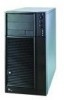
...Intel® Entry Server Chassis SC5275-E User Guide 1 Hex head 6-32 x 6mm [.256] Figure 1. A hard drive bay cage designed to hold half-height standard removable media devices. unused expansion slots must have a slot cover Covers installed over the external access. Flat head 6-32 x 5mm [.200] B. Cooling Two system fans inside the chassis and one power supply...One 3.5-inch diskette drive bay, accessible from front. Power Supply 600 Watt PFC power supply. 1 Chassis Description 1 Chassis Description Kit Contents The chassis subassembly kit includes this product guide and a box...
...Intel® Entry Server Chassis SC5275-E User Guide 1 Hex head 6-32 x 6mm [.256] Figure 1. A hard drive bay cage designed to hold half-height standard removable media devices. unused expansion slots must have a slot cover Covers installed over the external access. Flat head 6-32 x 5mm [.200] B. Cooling Two system fans inside the chassis and one power supply...One 3.5-inch diskette drive bay, accessible from front. Power Supply 600 Watt PFC power supply. 1 Chassis Description 1 Chassis Description Kit Contents The chassis subassembly kit includes this product guide and a box...
User Guide
Page 22
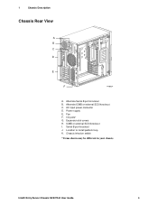
AC input power connector D. Expansion slot covers H. Serial B port knockout J. Alternate Serial B port knockout B. Chassis intrusion switch * Items shown may be different in your chassis. Intel® Entry Server Chassis SC5275-E User Guide 4 1 Chassis Description Chassis Rear View A B C D E F TP00834 A. Power supply E. Fan F. I . Location to install padlock loop K. Alternate ICMB or external SCSI knockout C. ICMB or external SCSI knockout I /O ports* G.
AC input power connector D. Expansion slot covers H. Serial B port knockout J. Alternate Serial B port knockout B. Chassis intrusion switch * Items shown may be different in your chassis. Intel® Entry Server Chassis SC5275-E User Guide 4 1 Chassis Description Chassis Rear View A B C D E F TP00834 A. Power supply E. Fan F. I . Location to install padlock loop K. Alternate ICMB or external SCSI knockout C. ICMB or external SCSI knockout I /O ports* G.
User Guide
Page 24
... supported on the server board. 1 Chassis Description Power Supply The 600-Watt PFC non-redundant power supply is auto ranging for more information. Checking the Power Cord WARNING Do not attempt to mains (AC power). The connector that... meets the following criteria: The cord must be readily accessible. This intrusion switch can be flexible (harmonized) or VDE certified cordage to the management controller on all server boards. It must be monitored by an agency acceptable in a number of the chassis. Intel® Entry Server Chassis SC5275...
... supported on the server board. 1 Chassis Description Power Supply The 600-Watt PFC non-redundant power supply is auto ranging for more information. Checking the Power Cord WARNING Do not attempt to mains (AC power). The connector that... meets the following criteria: The cord must be readily accessible. This intrusion switch can be flexible (harmonized) or VDE certified cordage to the management controller on all server boards. It must be monitored by an agency acceptable in a number of the chassis. Intel® Entry Server Chassis SC5275...

User Guide
Page 27
... the exception of the chassis. If you do not follow these instructions and the instructions supplied with other regional product laws and regulations. Tools and Supplies Needed Phillips (cross head) screwdriver (#2 bit) Small flathead screwdriver Antistatic wrist strap (recommended) Installation Safety Instructions Only technically qualified personnel should integrate this chassis subassembly. Intel® Entry Server Chassis SC5275-E User Guide 9
... the exception of the chassis. If you do not follow these instructions and the instructions supplied with other regional product laws and regulations. Tools and Supplies Needed Phillips (cross head) screwdriver (#2 bit) Small flathead screwdriver Antistatic wrist strap (recommended) Installation Safety Instructions Only technically qualified personnel should integrate this chassis subassembly. Intel® Entry Server Chassis SC5275-E User Guide 9

User Guide
Page 28
... surfaceon the server. 2 Setting Up the Chassis Warnings and Cautions These warnings and cautions apply whenever you remove the access cover(s) to access components inside the power supply. Turn off the AC power. If they do, ...server and disconnect the power cords, telecommunications systems, networks, and modems attached to chassis groundany surface. Intel® Entry Server Chassis SC5275-E User Guide 10 WARNINGS The power button on a grounded, static free surface. There are present inside the server. servicing should integrate and configure the server...
... surfaceon the server. 2 Setting Up the Chassis Warnings and Cautions These warnings and cautions apply whenever you remove the access cover(s) to access components inside the power supply. Turn off the AC power. If they do, ...server and disconnect the power cords, telecommunications systems, networks, and modems attached to chassis groundany surface. Intel® Entry Server Chassis SC5275-E User Guide 10 WARNINGS The power button on a grounded, static free surface. There are present inside the server. servicing should integrate and configure the server...

User Guide
Page 31
...power supply in place, and push it firmly into place all the way around. Figure 5. The shield fits the rectangular opening until it is required by Electromagnetic Interference (EMI) regulations. It minimizes EMI and ensures proper cooling of the chassis. Make sure the I /O Shield TP00074 Intel® Entry Server Chassis SC5275...-E User Guide 13 Position one edge of the chassis. Orient the shield so that the cutouts align with ...
...power supply in place, and push it firmly into place all the way around. Figure 5. The shield fits the rectangular opening until it is required by Electromagnetic Interference (EMI) regulations. It minimizes EMI and ensures proper cooling of the chassis. Make sure the I /O Shield TP00074 Intel® Entry Server Chassis SC5275...-E User Guide 13 Position one edge of the chassis. Orient the shield so that the cutouts align with ...

User Guide
Page 47
...protection by pressing the power button on the front panel DOES NOT turn off the server by wearing an antistatic wrist strap attached to the server. 2. Intel® Entry Server Chassis SC5275-E User Guide 29 Turn off the AC power. Only a technically ...qualified person should be present on the back of the chassis. 3. Turn off all telecommunication lines connected to the server before opening it has been set up. There are present inside it; Tools and Supplies...
...protection by pressing the power button on the front panel DOES NOT turn off the server by wearing an antistatic wrist strap attached to the server. 2. Intel® Entry Server Chassis SC5275-E User Guide 29 Turn off the AC power. Only a technically ...qualified person should be present on the back of the chassis. 3. Turn off all telecommunication lines connected to the server before opening it has been set up. There are present inside it; Tools and Supplies...

User Guide
Page 49
...Cage The front system fan is not necessary to pry up the four nylon rivets that hold the fan in a Standard Drive Cage Intel® Entry Server Chassis SC5275-E User Guide 31 To replace it, the cage must be necessary to push the cage out from all hard drives. 5. Remove...replaceable system fans. Slide the cage from the server board. 4. TP00078 Figure 17. It is located inside the hard drive bay cage. Disconnect the fan cable from the chassis. Remove the bezel. 3. Disconnect the cables from the back. 7. The power supply fan(s) are removing. Slide the fan out through...
...Cage The front system fan is not necessary to pry up the four nylon rivets that hold the fan in a Standard Drive Cage Intel® Entry Server Chassis SC5275-E User Guide 31 To replace it, the cage must be necessary to push the cage out from all hard drives. 5. Remove...replaceable system fans. Slide the cage from the server board. 4. TP00078 Figure 17. It is located inside the hard drive bay cage. Disconnect the fan cable from the chassis. Remove the bezel. 3. Disconnect the cables from the back. 7. The power supply fan(s) are removing. Slide the fan out through...

User Guide
Page 51
... hold the power supply to the power supply. Insert and tighten the screws that hold the power supply the chassis (four at the back of the chassis. 6. A A A A A A A. There are present inside the power supply. Remove the left access cover. 3. Remove the power supply from the power supply. 2. Replacing the AC Power Supply TP00068 Intel® Entry Server Chassis SC5275-E User Guide 33 3 Maintaining Your Server Replacing the Power Supply WARNINGS Hazardous conditions, power supply: Hazardous voltage...
... hold the power supply to the power supply. Insert and tighten the screws that hold the power supply the chassis (four at the back of the chassis. 6. A A A A A A A. There are present inside the power supply. Remove the left access cover. 3. Remove the power supply from the power supply. 2. Replacing the AC Power Supply TP00068 Intel® Entry Server Chassis SC5275-E User Guide 33 3 Maintaining Your Server Replacing the Power Supply WARNINGS Hazardous conditions, power supply: Hazardous voltage...

User Guide
Page 57
... 4. Intel® Entry Server Chassis SC5275-E User Guide 39 Exceeding a combined 179 Watts will overload the power subsystem and may cause the power supplies to overheat and malfunction. The expansion slots on the server board are rated for no more than 25 Watts for each voltage. 4 Technical Reference 4 Technical Reference Power Supply Specifications 600 Watt Single Power Supply Input Voltages 600 Watt Power Supply 100...
... 4. Intel® Entry Server Chassis SC5275-E User Guide 39 Exceeding a combined 179 Watts will overload the power subsystem and may cause the power supplies to overheat and malfunction. The expansion slots on the server board are rated for no more than 25 Watts for each voltage. 4 Technical Reference 4 Technical Reference Power Supply Specifications 600 Watt Single Power Supply Input Voltages 600 Watt Power Supply 100...

User Guide
Page 61
... of add-in this section to calculate the total used by your vendor documents. Worksheet, Calculating DC Power Usage Table 6. Power Usage Worksheet 1 Current (maximum) at voltage level: Device Baseboard, Front Panel Board and Fans Processor...12 V -12 V Total Current 5 V Standby Intel® Entry Server Chassis SC5275-E User Guide 43 Use the two worksheets in boards and peripherals, see your configuration. Equipment Log and Worksheets Current Usage Calculating Power Usage The total combined wattage for your configuration must be less than the wattage rating for your power supply.
... of add-in this section to calculate the total used by your vendor documents. Worksheet, Calculating DC Power Usage Table 6. Power Usage Worksheet 1 Current (maximum) at voltage level: Device Baseboard, Front Panel Board and Fans Processor...12 V -12 V Total Current 5 V Standby Intel® Entry Server Chassis SC5275-E User Guide 43 Use the two worksheets in boards and peripherals, see your configuration. Equipment Log and Worksheets Current Usage Calculating Power Usage The total combined wattage for your configuration must be less than the wattage rating for your power supply.

User Guide
Page 68
..., the modem must have the appropriate telecommunications, safety, and EMC approvals for configurations can be used and conditions adhered to. Maximum power rating of the power supply. Intel® Entry Server Chassis SC5275-E User Guide 50 Server boardyou do not have a printed wiring board flammability rating of other component will void the UL listing and other regulatory...
..., the modem must have the appropriate telecommunications, safety, and EMC approvals for configurations can be used and conditions adhered to. Maximum power rating of the power supply. Intel® Entry Server Chassis SC5275-E User Guide 50 Server boardyou do not have a printed wiring board flammability rating of other component will void the UL listing and other regulatory...
