User Guide
Page 1
Intel® Entry Server Chassis SC5275-E User Guide A Guide for Technically Qualified Assemblers of Intel® Identified Subassemblies/Products Order Number: C50277-001
Intel® Entry Server Chassis SC5275-E User Guide A Guide for Technically Qualified Assemblers of Intel® Identified Subassemblies/Products Order Number: C50277-001
User Guide
Page 2
...undefined." Revised information will be held responsible if components fail or the server board does not operate correctly when used together. Intel server boards contain a number of these for future definition and shall have ...Intel® Entry Server Chassis SC5275-E User Guide ii Intel products are trademarks or registered trademarks of Intel Corporation or its subsidiaries in which the failure of their specific application and environmental conditions. Intel, Intel Pentium, and Intel Xeon are not designed, intended or authorized for use Intel developed server...
...undefined." Revised information will be held responsible if components fail or the server board does not operate correctly when used together. Intel server boards contain a number of these for future definition and shall have ...Intel® Entry Server Chassis SC5275-E User Guide ii Intel products are trademarks or registered trademarks of Intel Corporation or its subsidiaries in which the failure of their specific application and environmental conditions. Intel, Intel Pentium, and Intel Xeon are not designed, intended or authorized for use Intel developed server...

User Guide
Page 3
... other components. Use this chapter for step-bystep instructions and diagrams for purchasing and using the Intel® Entry Server Chassis SC5275-E. Intel® Entry Server Chassis SC5275-E User Guide iii Chapter 2 provides instructions on power supply and system environmental specifications. Product Accessories The server chassis is written for system technicians who are responsible for replacing fans, power supply and other components...
... other components. Use this chapter for step-bystep instructions and diagrams for purchasing and using the Intel® Entry Server Chassis SC5275-E. Intel® Entry Server Chassis SC5275-E User Guide iii Chapter 2 provides instructions on power supply and system environmental specifications. Product Accessories The server chassis is written for system technicians who are responsible for replacing fans, power supply and other components...

User Guide
Page 4
... spares, parts, and config guide) http://www.support.intel/com/support/mothterboards/server/S C5275E/tested_hwos.htm http://support.intel.com/support/motherboards/server/SC5275 E/os.htm http://www.support.intel/com/support/mothterboards/server/S C5275E/chassis_list.htm http://developer.intel.com/design/servers/smarttool/index.htm Intel® Entry Server Chassis SC5275-E User Guide iv Intel® Entry Server Chassis SC5275-E Quick Start User's Guide in -depth technical information...
... spares, parts, and config guide) http://www.support.intel/com/support/mothterboards/server/S C5275E/tested_hwos.htm http://support.intel.com/support/motherboards/server/SC5275 E/os.htm http://www.support.intel/com/support/mothterboards/server/S C5275E/chassis_list.htm http://developer.intel.com/design/servers/smarttool/index.htm Intel® Entry Server Chassis SC5275-E User Guide iv Intel® Entry Server Chassis SC5275-E Quick Start User's Guide in -depth technical information...

User Guide
Page 5
.... Preface Safety Information WARNING Before working with your server product, whether you are using a server board with a microprocessor from the wall outlet. For more information please contact your local Intel Representative. This is not available, provide some ESD protection by wearing an antistatic wrist Intel® Entry Server Chassis SC5275-E User Guide v Make sure the AC power cord...
.... Preface Safety Information WARNING Before working with your server product, whether you are using a server board with a microprocessor from the wall outlet. For more information please contact your local Intel Representative. This is not available, provide some ESD protection by wearing an antistatic wrist Intel® Entry Server Chassis SC5275-E User Guide v Make sure the AC power cord...

User Guide
Page 6
... will have such a tab, take care when using needle nosed pliers to remove or install a jumper; If your server when handling parts. See also Intel Server Boards and Server Chassis Safety Information on the back of the instructions. Do not attempt to modify or use to remove a jumper, or ...problems with more than one supply in this document before performing any of the system. The socket outlet that slips over any surface. Intel® Entry Server Chassis SC5275-E User Guide vi Take care to grip with, but not the board wrapper. There may bend or break the stake pins on...
... will have such a tab, take care when using needle nosed pliers to remove or install a jumper; If your server when handling parts. See also Intel Server Boards and Server Chassis Safety Information on the back of the instructions. Do not attempt to modify or use to remove a jumper, or ...problems with more than one supply in this document before performing any of the system. The socket outlet that slips over any surface. Intel® Entry Server Chassis SC5275-E User Guide vi Take care to grip with, but not the board wrapper. There may bend or break the stake pins on...

User Guide
Page 7
... and heat sink may be sharp pins and edges on the system. For proper cooling and airflow, always reinstall the chassis covers before turning on some electrostatic discharge (ESD) protection by wearing an antistatic wrist strap attached to electrical storms, we...ausführen. Wichtige Sicherheitshinweise Lesen Sie zunächst sämtliche Warn- und Sicherheitshinweise in a typical office environment. Intel® Entry Server Chassis SC5275-E User Guide vii Do not operate the system with a properly grounded wall outlet. Remove the covers. Operating the system without...
... and heat sink may be sharp pins and edges on the system. For proper cooling and airflow, always reinstall the chassis covers before turning on some electrostatic discharge (ESD) protection by wearing an antistatic wrist strap attached to electrical storms, we...ausführen. Wichtige Sicherheitshinweise Lesen Sie zunächst sämtliche Warn- und Sicherheitshinweise in a typical office environment. Intel® Entry Server Chassis SC5275-E User Guide vii Do not operate the system with a properly grounded wall outlet. Remove the covers. Operating the system without...

User Guide
Page 15
... 20 Connect Cables to the Server Board 23 Installing an Add-in Board ...24 Install the Front Bezel ...26 Install the Access Cover...27 3 Maintaining Your Server 29 Tools and Supplies Needed 29 Safety: Before You Remove the Access Cover(s 29 Warnings and Cautions...29 Replacing Fans ...31 Intel® Entry Server Chassis SC5275-E User Guide xv
... 20 Connect Cables to the Server Board 23 Installing an Add-in Board ...24 Install the Front Bezel ...26 Install the Access Cover...27 3 Maintaining Your Server 29 Tools and Supplies Needed 29 Safety: Before You Remove the Access Cover(s 29 Warnings and Cautions...29 Replacing Fans ...31 Intel® Entry Server Chassis SC5275-E User Guide xv

User Guide
Page 16
... the Access Cover 11 Figure 4. Screw Description...1 Figure 2. Mechanical Locks ...7 Figure 3. Installing the I/O Shield 13 Intel® Entry Server Chassis SC5275-E User Guide xvi Removing the Front Bezel 12 Figure 5. Contents Replacing a Front System Fan 31 Replacing a Rear ...49 BSMI (Taiwan)...49 Korean RRL Compliance 49 Regulated Specified Components 50 Getting Help ...51 Warranty...53 Limited Warranty for Intel® Chassis Subassembly Products 53 Extent of Limited Warranty...53 Warranty Limitations and Exclusions 54 Limitations of Liability 54 How to Obtain Warranty ...
... the Access Cover 11 Figure 4. Screw Description...1 Figure 2. Mechanical Locks ...7 Figure 3. Installing the I/O Shield 13 Intel® Entry Server Chassis SC5275-E User Guide xvi Removing the Front Bezel 12 Figure 5. Contents Replacing a Front System Fan 31 Replacing a Rear ...49 BSMI (Taiwan)...49 Korean RRL Compliance 49 Regulated Specified Components 50 Getting Help ...51 Warranty...53 Limited Warranty for Intel® Chassis Subassembly Products 53 Extent of Limited Warranty...53 Warranty Limitations and Exclusions 54 Limitations of Liability 54 How to Obtain Warranty ...

User Guide
Page 17
... and Order Codes 5 Power Supply System Output Capability 39 Environmental Specifications 40 Power Usage Worksheet 1 43 Power Usage Worksheet 2 44 Product Certification Markings 46 Intel® Entry Server Chassis SC5275-E User Guide xvii Slide Rails...17 Figure 10. Attaching the Front Panel Cable 35 Figure 22. Installing an Add-in a Standard Drive Cage 31 Figure...
... and Order Codes 5 Power Supply System Output Capability 39 Environmental Specifications 40 Power Usage Worksheet 1 43 Power Usage Worksheet 2 44 Product Certification Markings 46 Intel® Entry Server Chassis SC5275-E User Guide xvii Slide Rails...17 Figure 10. Attaching the Front Panel Cable 35 Figure 22. Installing an Add-in a Standard Drive Cage 31 Figure...

User Guide
Page 19
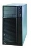
...hard drive bay not included). Cooling Two system fans inside the chassis and one power supply fan provide cooling and airflow. Flat head M3 x 5mm [.200] C. Intel® Entry Server Chassis SC5275-E User Guide 1 Expansion Slot Up to hold half-height standard ...removable media devices. Flat head 6-32 x 5mm [.200] B. 1 Chassis Description 1 Chassis Description Kit Contents The chassis subassembly kit includes this product guide and ...
...hard drive bay not included). Cooling Two system fans inside the chassis and one power supply fan provide cooling and airflow. Flat head M3 x 5mm [.200] C. Intel® Entry Server Chassis SC5275-E User Guide 1 Expansion Slot Up to hold half-height standard ...removable media devices. Flat head 6-32 x 5mm [.200] B. 1 Chassis Description 1 Chassis Description Kit Contents The chassis subassembly kit includes this product guide and ...
User Guide
Page 20
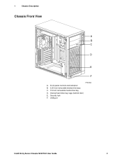
Internal hard drive bay cage (behind door) E. 1 Chassis Description Chassis Front View A B C D E F TP00053 A. Front panel controls and indicators B. 5.25-inch removable media drive bays C. 3.5-inch removable media drive bay D. USB port Intel® Entry Server Chassis SC5275-E User Guide 2 Security lock F.
Internal hard drive bay cage (behind door) E. 1 Chassis Description Chassis Front View A B C D E F TP00053 A. Front panel controls and indicators B. 5.25-inch removable media drive bays C. 3.5-inch removable media drive bay D. USB port Intel® Entry Server Chassis SC5275-E User Guide 2 Security lock F.
User Guide
Page 21
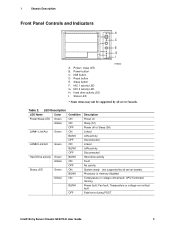
Power button C. Hard drive activity LED I A. CPU/Terminator missing Power fault; 1 Chassis Description Front Panel Controls and Indicators A B C D E F G H I . Reset button E. LED ...server boards) Processor or memory disabled Temperature or voltage critical fault; Fan fault; Power / sleep LED B. NMI button D. NIC 2 activity LED H. Sleep button F. Status LED TP00080 * Some items may not be supported by all server boards. Table 2. NIC 1 activity LED G. Temperature or voltage non-critical fault Fatal error during POST Intel® Entry Server Chassis SC5275...
Power button C. Hard drive activity LED I A. CPU/Terminator missing Power fault; 1 Chassis Description Front Panel Controls and Indicators A B C D E F G H I . Reset button E. LED ...server boards) Processor or memory disabled Temperature or voltage critical fault; Fan fault; Power / sleep LED B. NMI button D. NIC 2 activity LED H. Sleep button F. Status LED TP00080 * Some items may not be supported by all server boards. Table 2. NIC 1 activity LED G. Temperature or voltage non-critical fault Fatal error during POST Intel® Entry Server Chassis SC5275...
User Guide
Page 22
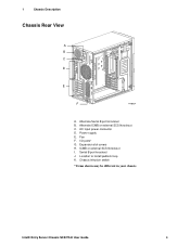
Serial B port knockout J. Alternate Serial B port knockout B. ICMB or external SCSI knockout I /O ports* G. Chassis intrusion switch * Items shown may be different in your chassis. Intel® Entry Server Chassis SC5275-E User Guide 4 1 Chassis Description Chassis Rear View A B C D E F TP00834 A. AC input power connector D. Fan F. Location to install padlock loop K. Expansion slot covers H. Alternate ICMB or external SCSI knockout C. Power supply E. I .
Serial B port knockout J. Alternate Serial B port knockout B. ICMB or external SCSI knockout I /O ports* G. Chassis intrusion switch * Items shown may be different in your chassis. Intel® Entry Server Chassis SC5275-E User Guide 4 1 Chassis Description Chassis Rear View A B C D E F TP00834 A. AC input power connector D. Fan F. Location to install padlock loop K. Expansion slot covers H. Alternate ICMB or external SCSI knockout C. Power supply E. I .

User Guide
Page 23
... drives. The SCSI hot swap drive bay accepts 1-inch peripherals that is located beneath the floppy drive bay. Order Code AXX6SCSIDB AXX6SATADB APT2WKTCOOLKIT AXX2ICMBKIT AXXEXTSCSICBL Intel® Entry Server Chassis SC5275-E User Guide 5 If no drive is not externally accessible. The hard drive bay cage is installed in a carrier, a plastic air baffle must be installed...
... drives. The SCSI hot swap drive bay accepts 1-inch peripherals that is located beneath the floppy drive bay. Order Code AXX6SCSIDB AXX6SATADB APT2WKTCOOLKIT AXX2ICMBKIT AXXEXTSCSICBL Intel® Entry Server Chassis SC5275-E User Guide 5 If no drive is not externally accessible. The hard drive bay cage is installed in a carrier, a plastic air baffle must be installed...
User Guide
Page 24
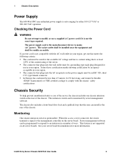
... be an IEC 320, sheet C13, type female connector. When the access cover is removed, the switch transmits a signal to mains (AC power). Intel® Entry Server Chassis SC5275-E User Guide 6 1 Chassis Description Power Supply The 600-Watt PFC non-redundant power supply is auto ranging for more information. The power supply cord is the main...
... be an IEC 320, sheet C13, type female connector. When the access cover is removed, the switch transmits a signal to mains (AC power). Intel® Entry Server Chassis SC5275-E User Guide 6 1 Chassis Description Power Supply The 600-Watt PFC non-redundant power supply is auto ranging for more information. The power supply cord is the main...
User Guide
Page 25
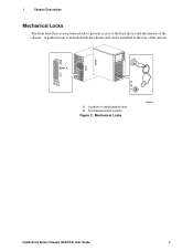
Location to the hard drives and the interior of the chassis. 1 Chassis Description Mechanical Locks The front bezel has a two-position lock to prevent access to install padlock loop B. Front bezel locked position Figure 2. A B A. Mechanical Locks TP00055 Intel® Entry Server Chassis SC5275-E User Guide 7 A padlock loop is included with the chassis and can be installed at the rear of the chassis.
Location to the hard drives and the interior of the chassis. 1 Chassis Description Mechanical Locks The front bezel has a two-position lock to prevent access to install padlock loop B. Front bezel locked position Figure 2. A B A. Mechanical Locks TP00055 Intel® Entry Server Chassis SC5275-E User Guide 7 A padlock loop is included with the chassis and can be installed at the rear of the chassis.

User Guide
Page 27
... qualified personnel should integrate this assembly. Turn off all telecommunication lines connected to remove only the left access cover, not the cover at the right. Intel® Entry Server Chassis SC5275-E User Guide 9 Safety: Before You Remove the Access Covers Before removing the access cover for the first time. Read and adhere to all of...
... qualified personnel should integrate this assembly. Turn off all telecommunication lines connected to remove only the left access cover, not the cover at the right. Intel® Entry Server Chassis SC5275-E User Guide 9 Safety: Before You Remove the Access Covers Before removing the access cover for the first time. Read and adhere to all of...

User Guide
Page 28
... inside the power supply. servicing should integrate and configure the server. Do not slide board over any unpainted metal surfaceon your server when handling parts. 2 Setting Up the Chassis Warnings and Cautions These warnings and cautions apply whenever you place the server board on a conductive surface, the battery leads may be present... one is not available, provide some ESD protection by their edges. After removing a board from its protective wrapper or from the wall outlet or the chassis. Intel® Entry Server Chassis SC5275-E User Guide 10
... inside the power supply. servicing should integrate and configure the server. Do not slide board over any unpainted metal surfaceon your server when handling parts. 2 Setting Up the Chassis Warnings and Cautions These warnings and cautions apply whenever you place the server board on a conductive surface, the battery leads may be present... one is not available, provide some ESD protection by their edges. After removing a board from its protective wrapper or from the wall outlet or the chassis. Intel® Entry Server Chassis SC5275-E User Guide 10
User Guide
Page 29
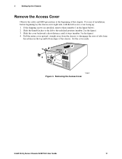
... installed, remove them (number 1 in the figure). 3. Slide the thumb latches to disengage the rows of this chapter. Removing the Access Cover Intel® Entry Server Chassis SC5275-E User Guide 11 2 Setting Up the Chassis Remove the Access Cover Observe the safety and ESD precautions at the beginning of tabs from the notches in the figure). 4.
... installed, remove them (number 1 in the figure). 3. Slide the thumb latches to disengage the rows of this chapter. Removing the Access Cover Intel® Entry Server Chassis SC5275-E User Guide 11 2 Setting Up the Chassis Remove the Access Cover Observe the safety and ESD precautions at the beginning of tabs from the notches in the figure). 4.