
Product Specification
Page 16
... processor socket) ƒ Channels A, B, C, D, E, and F • Support for 800/1066/1333 MT/s ECC Registered DDR3 Memory (RDIMM), ECC Unbuffered DDR3 memory ((UDIMM) • No support for mixing of RDIMMs and UDIMMs • Intel® Server Board S5520HC/S5520HCT: ƒ...One DIMM slot on Channels D, E, and F • Intel® Server Board S5520HC/S5520HCT: ƒ Intel® 5520 Chipset ƒ Intel® 82801JIR I/O Controller Hub (ICH10R) • Intel® Server Board S5500HCV: ƒ Intel® 5500 Chipset ƒ Intel® 82801JIR I/O Controller Hub (ICH10R) Support for •...
... processor socket) ƒ Channels A, B, C, D, E, and F • Support for 800/1066/1333 MT/s ECC Registered DDR3 Memory (RDIMM), ECC Unbuffered DDR3 memory ((UDIMM) • No support for mixing of RDIMMs and UDIMMs • Intel® Server Board S5520HC/S5520HCT: ƒ...One DIMM slot on Channels D, E, and F • Intel® Server Board S5520HC/S5520HCT: ƒ Intel® 5520 Chipset ƒ Intel® 82801JIR I/O Controller Hub (ICH10R) • Intel® Server Board S5500HCV: ƒ Intel® 5500 Chipset ƒ Intel® 82801JIR I/O Controller Hub (ICH10R) Support for •...
Product Specification
Page 21
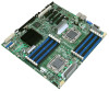
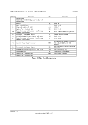
...Intel® Server Boards S5520HC, S5500HCV, and S5520HCT TPS Overview Callout I J K L M N O P Description Mechanically) S5500HCV: Slot 6, PCI Express* Gen2 x4 (x16 Mechanically) Battery Back Panel I/O Ports Diagnostic and Identify LED's System Fan 5 Header (4-pin) Power Connector for Processor 1 and Memory attached to Processor 1 Processor 1 Fan Header (4-pin) DIMM Sockets... 2 and Memory attached to Processor 2 Q Auxiliary Power Signal Connector R Processor 2 Fan Header (4-pin) S DIMM Sockets of Memory Channel D, E, and F T SAS Module Slot U System Fan 3 Header (6-pin) V System Fan ...
...Intel® Server Boards S5520HC, S5500HCV, and S5520HCT TPS Overview Callout I J K L M N O P Description Mechanically) S5500HCV: Slot 6, PCI Express* Gen2 x4 (x16 Mechanically) Battery Back Panel I/O Ports Diagnostic and Identify LED's System Fan 5 Header (4-pin) Power Connector for Processor 1 and Memory attached to Processor 1 Processor 1 Fan Header (4-pin) DIMM Sockets... 2 and Memory attached to Processor 2 Q Auxiliary Power Signal Connector R Processor 2 Fan Header (4-pin) S DIMM Sockets of Memory Channel D, E, and F T SAS Module Slot U System Fan 3 Header (6-pin) V System Fan ...

Product Specification
Page 31
... /O subsystem This chapter provides a high-level description of the Intel® Server Boards S5520HC, S5500HCV and S5520HCTis based on the Intel® Xeon® Processor 5500 Series in an FC-LGA 1366 Socket B package with each chipset component and the architectural blocks that... The architecture and design of the functionality associated with Intel® QuickPath Interconnect (Intel® QPI) speed at 6.40 GT/s, 5.86 GT/s, and 4.80 GT/s. The chipset contains two main components: - Intel® Server Boards S5520HC, S5500HCV, and S5520HCT TPS Functional Architecture 3.
... /O subsystem This chapter provides a high-level description of the Intel® Server Boards S5520HC, S5500HCV and S5520HCTis based on the Intel® Xeon® Processor 5500 Series in an FC-LGA 1366 Socket B package with each chipset component and the architectural blocks that... The architecture and design of the functionality associated with Intel® QuickPath Interconnect (Intel® QPI) speed at 6.40 GT/s, 5.86 GT/s, and 4.80 GT/s. The chipset contains two main components: - Intel® Server Boards S5520HC, S5500HCV, and S5520HCT TPS Functional Architecture 3.

Product Specification
Page 36
... the following table describes mixed processor conditions and recommended actions for the Intel® Server Boards S5520HC, S5500HCV and S5520HCT. The system cannot boot unless the error is displayed on the screen or on the Error Manager screen, ... boards do not support previous generations of supported processors, see: http://support.intel.com/support/motherboards/server/S5520HC/. For optimum performance, when two processors are installed, both must populate processors in the second processor socket. After entering setup, the error message displays on the Error Manager screen....
... the following table describes mixed processor conditions and recommended actions for the Intel® Server Boards S5520HC, S5500HCV and S5520HCT. The system cannot boot unless the error is displayed on the screen or on the Error Manager screen, ... boards do not support previous generations of supported processors, see: http://support.intel.com/support/motherboards/server/S5520HC/. For optimum performance, when two processors are installed, both must populate processors in the second processor socket. After entering setup, the error message displays on the Error Manager screen....

Product Specification
Page 39
This is enabled. 3.2.9 Unified Retention System Support The server boards comply with Unified Backplate Assembly at each processor socket. The BIOS setup provides an option to enable or disable this through hints to the processor to perform a data pre-... and only require a Phillips* screwdriver to attach to the Unified Backplate Assembly. All components of URS components. Intel® Server Boards S5520HC, S5500HCV, and S5520HCT TPS Functional Architecture z Intel® 64 mode when 64-bit extension technology is enabled. 3.2.7 Core Multi-Processing The BIOS setup provides the...
This is enabled. 3.2.9 Unified Retention System Support The server boards comply with Unified Backplate Assembly at each processor socket. The BIOS setup provides an option to enable or disable this through hints to the processor to perform a data pre-... and only require a Phillips* screwdriver to attach to the Unified Backplate Assembly. All components of URS components. Intel® Server Boards S5520HC, S5500HCV, and S5520HCT TPS Functional Architecture z Intel® 64 mode when 64-bit extension technology is enabled. 3.2.7 Core Multi-Processing The BIOS setup provides the...

Product Specification
Page 41
... memory. 3.3.1 Memory Subsystem Nomenclature The nomenclature for DIMM sockets implemented in the Intel® Server Boards S5520HC, S5500HCV and S5520HCT is the first slot on Channel A of CPU 2 Socket. z DIMMs are populated on CPU sockets. z The DIMM identifiers on the silkscreen on Channel D of CPU 1 socket. The Intel® Server Board S5520HC supports six DDR3 memory channels...
... memory. 3.3.1 Memory Subsystem Nomenclature The nomenclature for DIMM sockets implemented in the Intel® Server Boards S5520HC, S5500HCV and S5520HCT is the first slot on Channel A of CPU 2 Socket. z DIMMs are populated on CPU sockets. z The DIMM identifiers on the silkscreen on Channel D of CPU 1 socket. The Intel® Server Board S5520HC supports six DDR3 memory channels...

Product Specification
Page 43
... Boards S5520HC, S5500HCV, and S5520HCT TPS Functional Architecture Server Board CPU Socket Intel® Server S5500HCV CPU 1 Board CPU 2 DIMM Identifier A1 (Blue) A2 (Black) B1 (Blue) B2 (Black) C1 (Blue) C2 (Black) D1 (Blue) E1 (Blue) F1 (...
... Boards S5520HC, S5500HCV, and S5520HCT TPS Functional Architecture Server Board CPU Socket Intel® Server S5500HCV CPU 1 Board CPU 2 DIMM Identifier A1 (Blue) A2 (Black) B1 (Blue) B2 (Black) C1 (Blue) C2 (Black) D1 (Blue) E1 (Blue) F1 (...

Product Specification
Page 47
... errors. Demand scrubbing is not possible when memory mirroring is configured for both CPU sockets are installed in slots for mirroring, the BIOS disables it automatically. 3.3.8 Memory RAS 3.3.8.1 RAS Features The Intel® Server Boards S5520HC, S5500HCV and S5520HCT support the following memory channel modes: • Independent Channel Mode • Mirrored Channel Mode...
... errors. Demand scrubbing is not possible when memory mirroring is configured for both CPU sockets are installed in slots for mirroring, the BIOS disables it automatically. 3.3.8 Memory RAS 3.3.8.1 RAS Features The Intel® Server Boards S5520HC, S5500HCV and S5520HCT support the following memory channel modes: • Independent Channel Mode • Mirrored Channel Mode...

Product Specification
Page 49
... BIOS. 8. If it fails to enable and operate CPU2 socket. 3. The BIOS selects the mode that mode. Mirrored Channel Mode is local to the Independent Channel mode. 12. Intel® Server Boards S5520HC, S5500HCV, and S5520HCT TPS Functional Architecture • Optimization techniques used by default. ... default to the CPU socket. Also, you must observe and apply the following two modes are supported: Independent Channel Mode and Mirrored Channel Mode. 9. Revision 1.8 35 Intel order number E39529-013 In this mode becomes the default mode of the parameters, channel RAS still...
... BIOS. 8. If it fails to enable and operate CPU2 socket. 3. The BIOS selects the mode that mode. Mirrored Channel Mode is local to the Independent Channel mode. 12. Intel® Server Boards S5520HC, S5500HCV, and S5520HCT TPS Functional Architecture • Optimization techniques used by default. ... default to the CPU socket. Also, you must observe and apply the following two modes are supported: Independent Channel Mode and Mirrored Channel Mode. 9. Revision 1.8 35 Intel order number E39529-013 In this mode becomes the default mode of the parameters, channel RAS still...

Product Specification
Page 50
...DIMMs that were validated. DIMM_A1 and DIMM_B1 as a pair must DIMM_D1 and DIMM_E1 as a pair. The DIMMs on the Intel® Server Boards S5520HC, S5500HCV and S5520HCT. 3.3.10.1.1 Levels of support The following : Y indicating Yes; Validated configurations are highlighted in dark gray in Tables ...10 Supported Memory Configuration 3.3.10.1 Supported Memory Configurations The following sections describe the memory configurations supported and validated on different CPU sockets need not be identical, and so must be identical in Tables 5 and 6. ƒ Validated - Indicates the DIMM ...
...DIMMs that were validated. DIMM_A1 and DIMM_B1 as a pair must DIMM_D1 and DIMM_E1 as a pair. The DIMMs on the Intel® Server Boards S5520HC, S5500HCV and S5520HCT. 3.3.10.1.1 Levels of support The following : Y indicating Yes; Validated configurations are highlighted in dark gray in Tables ...10 Supported Memory Configuration 3.3.10.1 Supported Memory Configurations The following sections describe the memory configurations supported and validated on different CPU sockets need not be identical, and so must be identical in Tables 5 and 6. ƒ Validated - Indicates the DIMM ...

Product Specification
Page 51
... Population under the Single Processor Configuration # N CPU1 Socket = Populated CPU2 Socket = Empty A1 A2 B1 B2 C1 C2 D1 D2 E1 E2 F1 F2 M 1 1 X N 2 2 X X N 3 2 X X Y 4 3 X X X N 5 4 X X X X N 6 4 X X X X Y 7 6 X X X X X X N Note: The generic principles and guidelines described in the above sections also apply to the above two tables. Intel® Server Boards S5520HC, S5500HCV, and S5520HCT TPS Functional Architecture Table 5.
... Population under the Single Processor Configuration # N CPU1 Socket = Populated CPU2 Socket = Empty A1 A2 B1 B2 C1 C2 D1 D2 E1 E2 F1 F2 M 1 1 X N 2 2 X X N 3 2 X X Y 4 3 X X X N 5 4 X X X X N 6 4 X X X X Y 7 6 X X X X X X N Note: The generic principles and guidelines described in the above sections also apply to the above two tables. Intel® Server Boards S5520HC, S5500HCV, and S5520HCT TPS Functional Architecture Table 5.

Product Specification
Page 93
... Socket Processor ID Processor Frequency Microcode Revision L1 Cache RAM L2 Cache RAM L3 Cache RAM Processor 1 Version Processor 2 Version Current Intel® QPI Link Speed Intel® QPI Link Frequency Intel® Turbo Boost Technology Enhanced Intel SpeedStep® Tech Intel®... Enabled/Disabled Enabled/ Disabled Enabled/Disabled Enabled/Disabled Enabled/Disabled Enabled/Disabled Enabled/Disabled Figure 30. Intel® Server Boards S5520HC, S5500HCV, and S5520HCT TPS BIOS Setup Utility 5.3.2.2.1 Processor Configuration Screen The Processor screen allows the user to view the ...
... Socket Processor ID Processor Frequency Microcode Revision L1 Cache RAM L2 Cache RAM L3 Cache RAM Processor 1 Version Processor 2 Version Current Intel® QPI Link Speed Intel® QPI Link Frequency Intel® Turbo Boost Technology Enhanced Intel SpeedStep® Tech Intel®... Enabled/Disabled Enabled/ Disabled Enabled/Disabled Enabled/Disabled Enabled/Disabled Enabled/Disabled Enabled/Disabled Figure 30. Intel® Server Boards S5520HC, S5500HCV, and S5520HCT TPS BIOS Setup Utility 5.3.2.2.1 Processor Configuration Screen The Processor screen allows the user to view the ...

Product Specification
Page 97
... the system in the form of installed DDR3 DIMMs in MB or GB. Select to the operating system in units of each DIMM socket present on the board. Displays the speed the memory is no RAS is configured for internal usage, RAS redundancy and SMRAM. Memory... Installed: There is running at. Disabled: The DDR3 DIMM installed in the form of the following possible states: - Intel® Server Boards S5520HC, S5500HCV, and S5520HCT TPS BIOS Setup Utility Setup Item Total Memory Effective Memory Current Configuration Current Memory Speed Memory RAS and Performance Configuration DIMM_ ...
... the system in the form of installed DDR3 DIMMs in MB or GB. Select to the operating system in units of each DIMM socket present on the board. Displays the speed the memory is no RAS is configured for internal usage, RAS redundancy and SMRAM. Memory... Installed: There is running at. Disabled: The DDR3 DIMM installed in the form of the following possible states: - Intel® Server Boards S5520HC, S5500HCV, and S5520HCT TPS BIOS Setup Utility Setup Item Total Memory Effective Memory Current Configuration Current Memory Speed Memory RAS and Performance Configuration DIMM_ ...

Product Specification
Page 122
..., J1E3, J1F1, J1F4 J1F5, J1G3 J1G2 J1G6 Connector Type Main power CPU 1 power CPU 2 Power P/S aux/IPMB CPU sockets DIMM sockets Card edge Card edge Card edge Mezzanine Mezzanine Key holder Header Header Header Battery holder External LAN built-in magnetic and dual USB...The following table lists all connectors, headers, and jumpers on the silkscreen. Connector/Header Locations and Pin-outs Intel® Server Boards S5520HC, S5500HCV, and S5520HCT TPS 6. The following section provides detailed information regarding all connector types available on the board and the corresponding preference...
..., J1E3, J1F1, J1F4 J1F5, J1G3 J1G2 J1G6 Connector Type Main power CPU 1 power CPU 2 Power P/S aux/IPMB CPU sockets DIMM sockets Card edge Card edge Card edge Mezzanine Mezzanine Key holder Header Header Header Battery holder External LAN built-in magnetic and dual USB...The following table lists all connectors, headers, and jumpers on the silkscreen. Connector/Header Locations and Pin-outs Intel® Server Boards S5520HC, S5500HCV, and S5520HCT TPS 6. The following section provides detailed information regarding all connector types available on the board and the corresponding preference...

Product Specification
Page 140
Intel® Light Guided Diagnostics Intel® Server Boards S5520HC, S5500HCV, and S5520HCT TPS 8.4 DIMM Fault LEDs The server boards provide memory fault LED for each DIMM socket. DIMM Fault LED's Location 126 Revision 1.8 Intel order number E39529-013 The DIMM fault LED illuminates when the corresponding DIMM slot has memory installed and a memory error occurs. * D2, E2, and F2 DIMM slot and Fault LED's are located as shown in Intel® Server Board S5500HCV Figure 57. These LEDs are empty in the following figure.
Intel® Light Guided Diagnostics Intel® Server Boards S5520HC, S5500HCV, and S5520HCT TPS 8.4 DIMM Fault LEDs The server boards provide memory fault LED for each DIMM socket. DIMM Fault LED's Location 126 Revision 1.8 Intel order number E39529-013 The DIMM fault LED illuminates when the corresponding DIMM slot has memory installed and a memory error occurs. * D2, E2, and F2 DIMM slot and Fault LED's are located as shown in Intel® Server Board S5500HCV Figure 57. These LEDs are empty in the following figure.

Product Specification
Page 159
... does not support previous generation Intel® Xeon® processors. • You must remove the AC power cord. CPU 1 socket is powered off. • This server board supports Intel® Xeon® Processor 5500 Series only. Revision 1.8 145 Intel order number E39529-013 With AC...DDR3 DIMMs installed across both processor sockets and memory channels. the higher four bits of ED3 byte provides the device number, and the lower four bits of ED2 provides the PCI device bus number; Intel® Server Boards S5520HC, S5500HCV, and S5520HCT TPS Appendix A: Integration and ...
... does not support previous generation Intel® Xeon® processors. • You must remove the AC power cord. CPU 1 socket is powered off. • This server board supports Intel® Xeon® Processor 5500 Series only. Revision 1.8 145 Intel order number E39529-013 With AC...DDR3 DIMMs installed across both processor sockets and memory channels. the higher four bits of ED3 byte provides the device number, and the lower four bits of ED2 provides the PCI device bus number; Intel® Server Boards S5520HC, S5500HCV, and S5520HCT TPS Appendix A: Integration and ...

Product Specification
Page 183
...failure offset. Beep codes are sounded each time the problem is discovered, such as on the POST Progress LED's. Associated Sensors CPU sockets are not sounded continuously. The beep code is equal to the digit. Power control fault (power good assertion timeout). Prior to ...Power fault: DC power unexpectedly lost (power good dropout). Revision 1.8 169 Intel order number E39529-013 The BMC may generate beep codes upon detection of error conditions. Intel® Server Boards S5520HC, S5500HCV and S5520HCT TPS Appendix F: POST Error Messages and Handling POST Error Beep Codes The ...
...failure offset. Beep codes are sounded each time the problem is discovered, such as on the POST Progress LED's. Associated Sensors CPU sockets are not sounded continuously. The beep code is equal to the digit. Power control fault (power good assertion timeout). Prior to ...Power fault: DC power unexpectedly lost (power good dropout). Revision 1.8 169 Intel order number E39529-013 The BMC may generate beep codes upon detection of error conditions. Intel® Server Boards S5520HC, S5500HCV and S5520HCT TPS Appendix F: POST Error Messages and Handling POST Error Beep Codes The ...

