
Product Specification
Page 9
...86 Figure 40. Boot Manager Screen 87 Figure 43. Output Voltage Timing 115 Figure 50. Floppy Order Screen 85 Figure 38. Intel®Server Board S1200BT TPS List of Figures Figure 33. POST Code Diagnostic LED Location 110 Figure 49. Boot Options Screen 83 Figure 35. Realtime Teperature... and Voltage Status Screen (S1200BTS 82 Figure 34. Add EFI Boot Option Screen 86 Figure 41. Exit Screen ...89 Figure 46. Turn On/Off Timing (Power Supply Signals 116 Revision 1.0 ix Intel order number G13326-003
...86 Figure 40. Boot Manager Screen 87 Figure 43. Output Voltage Timing 115 Figure 50. Floppy Order Screen 85 Figure 38. Intel®Server Board S1200BT TPS List of Figures Figure 33. POST Code Diagnostic LED Location 110 Figure 49. Boot Options Screen 83 Figure 35. Realtime Teperature... and Voltage Status Screen (S1200BTS 82 Figure 34. Add EFI Boot Option Screen 86 Figure 41. Exit Screen ...89 Figure 46. Turn On/Off Timing (Power Supply Signals 116 Revision 1.0 ix Intel order number G13326-003

Product Specification
Page 11
... module (J3F2 99 Table 38. Server Board Jumpers (J1F1, J1F2, J1F3, J1E2, and J4A2) on S1200BTS 105 Table 44. Front Panel LED Behavior Summary 109 Table 45. Transient Load Requirements 113 Table 50. Capacitve...114 Table 51. Over-Current Protection (OCP 117 Table 55. Server Board Design Specifications 111 Table 46. Intel® Xeon® Processor TDP Guidelines 112 Table 47. 350-W Load Ratings 112 Table 48. Voltage .... Internal 9-pin Serial B Header Pin-out (J1B2 98 Table 36. Turn On/Off Timing 116 Table 54. Intel®Server Board S1200BT TPS List of Tables Table 33.
... module (J3F2 99 Table 38. Server Board Jumpers (J1F1, J1F2, J1F3, J1E2, and J4A2) on S1200BTS 105 Table 44. Front Panel LED Behavior Summary 109 Table 45. Transient Load Requirements 113 Table 50. Capacitve...114 Table 51. Over-Current Protection (OCP 117 Table 55. Server Board Design Specifications 111 Table 46. Intel® Xeon® Processor TDP Guidelines 112 Table 47. 350-W Load Ratings 112 Table 48. Voltage .... Internal 9-pin Serial B Header Pin-out (J1B2 98 Table 36. Turn On/Off Timing 116 Table 54. Intel®Server Board S1200BT TPS List of Tables Table 33.

Product Specification
Page 46
... data / system information export (partial SMBIOS table) Enhancements to embedded web server 34 Revision 1.0 Intel order number G13326-003 The following is turned on the previous generation of changes and additions to the manageability features that are supported on using a front panel...; Embedded platform debug feature which allows capture of certain front panel functionality and monitors button presses. Platform Management Intel®Server Board S1200BT TPS Signal testing support: The BMC provides test commands for setting and getting platform signal states. ...
... data / system information export (partial SMBIOS table) Enhancements to embedded web server 34 Revision 1.0 Intel order number G13326-003 The following is turned on the previous generation of changes and additions to the manageability features that are supported on using a front panel...; Embedded platform debug feature which allows capture of certain front panel functionality and monitors button presses. Platform Management Intel®Server Board S1200BT TPS Signal testing support: The BMC provides test commands for setting and getting platform signal states. ...

Product Specification
Page 87
... Panel Lockout [1234aBcD] [1234aBcD] Enabled/Disabled TPM State TPM Administrative Control No Operation/Turn On/Turn Off/Clear Ownership Figure 24. Security Screen Revision 1.0 75 Intel order number G13326-003 To access this screen from the Main screen or other top-...level Tab screen, press the right or left arrow keys to the Advanced screen, then select the desired screen. Intel®Server Board S1200BT...
... Panel Lockout [1234aBcD] [1234aBcD] Enabled/Disabled TPM State TPM Administrative Control No Operation/Turn On/Turn Off/Clear Ownership Figure 24. Security Screen Revision 1.0 75 Intel order number G13326-003 To access this screen from the Main screen or other top-...level Tab screen, press the right or left arrow keys to the Advanced screen, then select the desired screen. Intel®Server Board S1200BT...

Product Specification
Page 106
... (SCI) is running, pressing the power button switch generates a request using a bridge board and a hot- Connector/Header Locations and Pin-outs Intel®Server Board S1200BT TPS Pin Signal Name Pin Signal Name 1 P3V3_AUX 2 3 NC 4 5 PWR_LED_N 6 7 P3V3 8 9 LED_HDD_ACT_N 10 11 FP_PWR_BTN_N 12 13 ... the Integrated BMC and does not directly control power on the power supply. Power Button - Otherwise, the BIOS turns off the system in Intel® Server Systems configured using SCI to the operating system to 5 seconds. Power Button - Since the processor ...
... (SCI) is running, pressing the power button switch generates a request using a bridge board and a hot- Connector/Header Locations and Pin-outs Intel®Server Board S1200BT TPS Pin Signal Name Pin Signal Name 1 P3V3_AUX 2 3 NC 4 5 PWR_LED_N 6 7 P3V3 8 9 LED_HDD_ACT_N 10 11 FP_PWR_BTN_N 12 13 ... the Integrated BMC and does not directly control power on the power supply. Power Button - Otherwise, the BIOS turns off the system in Intel® Server Systems configured using SCI to the operating system to 5 seconds. Power Button - Since the processor ...

Product Specification
Page 107
Intel®Server Board S1200BT TPS Connector/Header Locations and Pin-outs 7.4.2 Reset Button The ...on the front panel. If the button is not provided in the default SDR configuration. Revision 1.0 95 Intel order number G13326-003 This indicator LED has specific states and corresponding interpretation as described. Critical temperature threshold ...-out mechanism for upper non-critical limit is pressed again with no intervening commands, the chassis ID LED turns off , if no longer has spared DIMMs indicating a redundancy lost , sufficient system cooling maintained. Corresponding ...
Intel®Server Board S1200BT TPS Connector/Header Locations and Pin-outs 7.4.2 Reset Button The ...on the front panel. If the button is not provided in the default SDR configuration. Revision 1.0 95 Intel order number G13326-003 This indicator LED has specific states and corresponding interpretation as described. Critical temperature threshold ...-out mechanism for upper non-critical limit is pressed again with no intervening commands, the chassis ID LED turns off , if no longer has spared DIMMs indicating a redundancy lost , sufficient system cooling maintained. Corresponding ...
Product Specification
Page 120
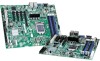
... number G13326-003 The EFI shell then executes the Startup.nsh batch file to the recovery state. 3. Jumper Blocks Intel®Server Board S1200BT TPS 1. For instructions, see your server chassis documentation. 3. Perform the ME firmware update procedure as documented in the README.TXT file...same package as user binary or language blocks. Move jumper from the default operating position (covering pins 1 and 2) to its original position. 4. Turn on the system power. When the flash update completes: 1. Restore the jumper to the EFI shell. Reconnect the AC cord and power up the...
... number G13326-003 The EFI shell then executes the Startup.nsh batch file to the recovery state. 3. Jumper Blocks Intel®Server Board S1200BT TPS 1. For instructions, see your server chassis documentation. 3. Perform the ME firmware update procedure as documented in the README.TXT file...same package as user binary or language blocks. Move jumper from the default operating position (covering pins 1 and 2) to its original position. 4. Turn on the system power. When the flash update completes: 1. Restore the jumper to the EFI shell. Reconnect the AC cord and power up the...
Product Specification
Page 125
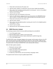
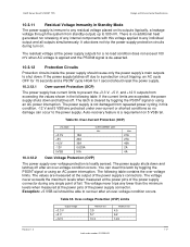
...used to carry DC current. 10.3.2 Standby Outputs The 5 VSB output is present when an AC input greater than the power supply turn on voltage is provided with reference to regulate out drops in the following voltage limits when operating at duty cycles ranging from the ...Units Vrms Vrms Vrms Vrms Vrms 10.3.5 Dynamic Loading The output voltages remain within the Min load to the Max load conditions. Intel®Server Board S1200BT TPS Design and Environmental Specifications 10.3.1 Grounding The grounds of the ground returns to chassis does not exceed 1.0 m. The load transient...
...used to carry DC current. 10.3.2 Standby Outputs The 5 VSB output is present when an AC input greater than the power supply turn on voltage is provided with reference to regulate out drops in the following voltage limits when operating at duty cycles ranging from the ...Units Vrms Vrms Vrms Vrms Vrms 10.3.5 Dynamic Loading The output voltages remain within the Min load to the Max load conditions. Intel®Server Board S1200BT TPS Design and Environmental Specifications 10.3.1 Grounding The grounds of the ground returns to chassis does not exceed 1.0 m. The load transient...

Product Specification
Page 127
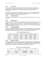
...output during any point of the voltage rise. The +5 V output must never be within regulation of each other when the power supply is turned on and off . Minimum 5.01 Maximum 701 50 700 The 5 VSB output voltage rise time should be from 1.0 ms to rise approximately at ... 25 ms. The +3.3 V, +5 V, and +12 V output voltages should start to 25.0 ms. Units Msec Msec Msec Figure 49. Intel®Server Board S1200BT TPS Design and Environmental Specifications The output voltages must rise from 10% to within regulation limits (Tvout_rise) within 5 ms to 70 ms, except...
...output during any point of the voltage rise. The +5 V output must never be within regulation of each other when the power supply is turned on and off . Minimum 5.01 Maximum 701 50 700 The 5 VSB output voltage rise time should be from 1.0 ms to rise approximately at ... 25 ms. The +3.3 V, +5 V, and +12 V output voltages should start to 25.0 ms. Units Msec Msec Msec Figure 49. Intel®Server Board S1200BT TPS Design and Environmental Specifications The output voltages must rise from 10% to within regulation limits (Tvout_rise) within 5 ms to 70 ms, except...
Product Specification
Page 128
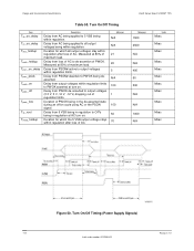
Design and Environmental Specifications Intel®Server Board S1200BT TPS Table 53. Delay from PSON# deactive to O/Ps being in the de-asserted state during an off/on cycle using AC or the PSON signal. Measured at AC turn on . Delay from PWOK de-asserted to output voltages ...PWOK asserted at 80% of maximum load. Duration of AC. Duration for which all output voltages being deasserted. Turn On/Off Timing (Power Supply Signals) 116 Revision 1.0 Intel order number G13326-003 Delay from output voltages within regulation. Minimum N/A N/A 21 20 5 N/A 100 1 100...
Design and Environmental Specifications Intel®Server Board S1200BT TPS Table 53. Delay from PSON# deactive to O/Ps being in the de-asserted state during an off/on cycle using AC or the PSON signal. Measured at AC turn on . Delay from PWOK de-asserted to output voltages ...PWOK asserted at 80% of maximum load. Duration of AC. Duration for which all output voltages being deasserted. Turn On/Off Timing (Power Supply Signals) 116 Revision 1.0 Intel order number G13326-003 Delay from output voltages within regulation. Minimum N/A N/A 21 20 5 N/A 100 1 100...
Product Specification
Page 129
...levels when measured at the output of the power supply connector. Exception: +5 VSB rail should be able to 500 mV. Intel®Server Board S1200BT TPS Design and Environmental Specifications 10.3.11 Residual Voltage Immunity in Standby Mode The power supply is immune to any residual voltage ... toggling the PSON# signal or using an AC power interruption. The residual voltage at the power pins of the power supply connector during turn on 5 VSB rail. The latch is locally sensed. The following table. You can occur to any internal components with this voltage applied...
...levels when measured at the output of the power supply connector. Exception: +5 VSB rail should be able to 500 mV. Intel®Server Board S1200BT TPS Design and Environmental Specifications 10.3.11 Residual Voltage Immunity in Standby Mode The power supply is immune to any residual voltage ... toggling the PSON# signal or using an AC power interruption. The residual voltage at the power pins of the power supply connector during turn on 5 VSB rail. The latch is locally sensed. The following table. You can occur to any internal components with this voltage applied...

