
Hardware User Guide
Page 7
... 18 Figure 9. SFF8087 to Four-port Internal Cable with one SGPIO Connector 20 Figure 10. LED Header ...22 Figure 11. UART Connector...24 Intel® RAID Controller RS25DB080 Hardware User's Guide vii Cache Memory Board 13 Figure 6. Installing the Intel® RAID Controller RS25DB080 9 Figure 3. Card Layout...13 Figure 5. Changing the Bracket 8 Figure 2. Connecting Cable between the...
... 18 Figure 9. SFF8087 to Four-port Internal Cable with one SGPIO Connector 20 Figure 10. LED Header ...22 Figure 11. UART Connector...24 Intel® RAID Controller RS25DB080 Hardware User's Guide vii Cache Memory Board 13 Figure 6. Installing the Intel® RAID Controller RS25DB080 9 Figure 3. Card Layout...13 Figure 5. Changing the Bracket 8 Figure 2. Connecting Cable between the...

Hardware User Guide
Page 9
.../Drive Fault Header (J1A5) Pin List 23 Table 7. Array Performance Features 25 Table 10. RAID Physical Drive Status 29 Table 13. UART Connector Pin-out 24 Table 8. Fault Tolerance Features 26 Table 11. RAID Virtual Drive Status 30 Intel® RAID Controller RS25DB080 Hardware User's Guide ix Jumper Description 14 Table 2. Actual Power Consumption Table 27...
.../Drive Fault Header (J1A5) Pin List 23 Table 7. Array Performance Features 25 Table 10. RAID Physical Drive Status 29 Table 13. UART Connector Pin-out 24 Table 8. Fault Tolerance Features 26 Table 11. RAID Virtual Drive Status 30 Intel® RAID Controller RS25DB080 Hardware User's Guide ix Jumper Description 14 Table 2. Actual Power Consumption Table 27...

Hardware User Guide
Page 12
... and RAID engine. Operating System Support • Windows Server 2008* R2, Windows 7*, Windows Server 2003*, Windows Vista*, and Windows XP* • Red Hat* Enterprise Linux 4.0, 5.0, and 6.0 • SuSE* Linux Enterprise Server 9, 10, and 11 • VMWare* ESX 4.0 • Solaris* 10 The ...Tested Hardware and Operating System List for your server board at http://www.intel.com/p/en_US/support/server. Intel® RAID Controller RS25DB080 The Intel® RAID Controller RS25DB080 is an intelligent, low-profile RAID adapter with other SAS devices. • SATA II Protocol to enable ...
... and RAID engine. Operating System Support • Windows Server 2008* R2, Windows 7*, Windows Server 2003*, Windows Vista*, and Windows XP* • Red Hat* Enterprise Linux 4.0, 5.0, and 6.0 • SuSE* Linux Enterprise Server 9, 10, and 11 • VMWare* ESX 4.0 • Solaris* 10 The ...Tested Hardware and Operating System List for your server board at http://www.intel.com/p/en_US/support/server. Intel® RAID Controller RS25DB080 The Intel® RAID Controller RS25DB080 is an intelligent, low-profile RAID adapter with other SAS devices. • SATA II Protocol to enable ...

Hardware User Guide
Page 13
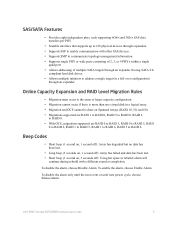
...Auto Rebuild feature must be set for Rebuilds, Consistency Checks, Initialization (auto restarting Consistency Check on OCE and RAID migration. - Online RAID level migration (upgrade of system resources to existing drive or new drive. Drive roaming - Redundancy and Error Handling...space to use from 0-100%). No reboot necessary after expansion - Intel® RAID Controller RS25DB080 Hardware User's Guide 3 Load Balancing • Upgradeable Flash ROM interface. • Allows for intelligent XOR RAID levels 0, 1, 5, 6, 10, 50, and 60. • Dedicated or global hot spare ...
...Auto Rebuild feature must be set for Rebuilds, Consistency Checks, Initialization (auto restarting Consistency Check on OCE and RAID migration. - Online RAID level migration (upgrade of system resources to existing drive or new drive. Drive roaming - Redundancy and Error Handling...space to use from 0-100%). No reboot necessary after expansion - Intel® RAID Controller RS25DB080 Hardware User's Guide 3 Load Balancing • Upgradeable Flash ROM interface. • Allows for intelligent XOR RAID levels 0, 1, 5, 6, 10, 50, and 60. • Dedicated or global hot spare ...
Hardware User Guide
Page 15
compliant hard disk drives. • Allows multiple initiators to address a single target (in rebuild; Intel® RAID Controller RS25DB080 Hardware User's Guide 5 Beep Codes • Short beep (1 second on, 1 second off): ...8226; Short beep (1 second on Spanned Arrays (RAID 10, 50, and 60). • Migrations supported are RAID 1 to RAID 0, RAID 5 to RAID 0, RAID 6 to RAID 0. • With OCE, migrations supported are RAID 0 to RAID 1, RAID 0 to RAID 5, RAID 0 to RAID 6, RAID 1 to RAID 5, RAID 1 to RAID 6, RAID 5 to RAID 6. alarm will continue during rebuild with other SAS ...
compliant hard disk drives. • Allows multiple initiators to address a single target (in rebuild; Intel® RAID Controller RS25DB080 Hardware User's Guide 5 Beep Codes • Short beep (1 second on, 1 second off): ...8226; Short beep (1 second on Spanned Arrays (RAID 10, 50, and 60). • Migrations supported are RAID 1 to RAID 0, RAID 5 to RAID 0, RAID 6 to RAID 0. • With OCE, migrations supported are RAID 0 to RAID 1, RAID 0 to RAID 5, RAID 0 to RAID 6, RAID 1 to RAID 5, RAID 1 to RAID 6, RAID 5 to RAID 6. alarm will continue during rebuild with other SAS ...
Hardware User Guide
Page 20
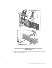
Install the server system cover and connect the power cords. See your server system documentation for instructions. 10 Intel® RAID Controller RS25DB080 Hardware User's Guide A C B Ports 0-3 Ports 4-7 D AF003885 Figure 3. Connecting Cable between the RAID Controller and Drives/Backplane 6.
Install the server system cover and connect the power cords. See your server system documentation for instructions. 10 Intel® RAID Controller RS25DB080 Hardware User's Guide A C B Ports 0-3 Ports 4-7 D AF003885 Figure 3. Connecting Cable between the RAID Controller and Drives/Backplane 6.

Hardware User Guide
Page 31
I2C Connector Pin-Out Pin Number 1 2 3 Description SMB_SAS_SES_SDA GND SMB_SAS_SES_SCL Intel® RAID Controller RS25DB080 Hardware User's Guide 21 BBU Connector Pin-out Pin # 1 2 3 4 5 6 7 8 9 10 11 12 13 14 15 16 17 18 19 20 Name P12V GND BATT_PRSNT GND P1V8 GND P3V3 GND VBB_DDR_MEM GND P3V3_STBY GND SCL GND ...
I2C Connector Pin-Out Pin Number 1 2 3 Description SMB_SAS_SES_SDA GND SMB_SAS_SES_SCL Intel® RAID Controller RS25DB080 Hardware User's Guide 21 BBU Connector Pin-out Pin # 1 2 3 4 5 6 7 8 9 10 11 12 13 14 15 16 17 18 19 20 Name P12V GND BATT_PRSNT GND P1V8 GND P3V3 GND VBB_DDR_MEM GND P3V3_STBY GND SCL GND ...
Hardware User Guide
Page 32
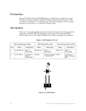
... 330? to P3V3_DUAL P3V3_DUAL DIRTY_PU 2 D_ACTIVE_N Connected to GFAULT Drain of onboard MFT Connected to GFAULT_PU 330? LED Header 22 Intel® RAID Controller RS25DB080 Hardware User's Guide Table 5. to Drain DIRTY of onboard MFT Description 330? to P3V3_DUAL Connected to indicate a pending write command...; RAID Controller RS25DB080 must be installed into a standard x8 or larger PCI Express* slot that are used for connection to external LED which indicate activity on any of the connected HDDs and to Drain of onboard MFT Figure 10. The controller is PCI Express* ...
... 330? to P3V3_DUAL P3V3_DUAL DIRTY_PU 2 D_ACTIVE_N Connected to GFAULT Drain of onboard MFT Connected to GFAULT_PU 330? LED Header 22 Intel® RAID Controller RS25DB080 Hardware User's Guide Table 5. to Drain DIRTY of onboard MFT Description 330? to P3V3_DUAL Connected to indicate a pending write command...; RAID Controller RS25DB080 must be installed into a standard x8 or larger PCI Express* slot that are used for connection to external LED which indicate activity on any of the connected HDDs and to Drain of onboard MFT Figure 10. The controller is PCI Express* ...
Hardware User Guide
Page 33
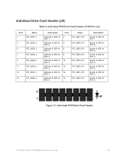
... of LED for PHY 4 Cathode of LED for PHY 3 Cathode of LED for PHY 2 Cathode of LED for PHY 1 Cathode of LED for PHY 0 Pin# 2 4 6 8 10 12 14 16 Name FLT_LED7_PU FLT_LED6_PU FLT_LED5_PU FLT_LED4_PU FLT_LED3_PU FLT_LED2_PU FLT_LED1_PU FLT_LED0_PU Description Anode of LED for PHY 7 Anode of LED for PHY 6 Anode of... for PHY 2 Anode of LED for PHY 1 Anode of LED for PHY 0 Figure 11. Individual Drive Fault Header (x8) Table 6. Individual PHY/Drive Fault Header Intel® RAID Controller RS25DB080 Hardware User's Guide 23
... of LED for PHY 4 Cathode of LED for PHY 3 Cathode of LED for PHY 2 Cathode of LED for PHY 1 Cathode of LED for PHY 0 Pin# 2 4 6 8 10 12 14 16 Name FLT_LED7_PU FLT_LED6_PU FLT_LED5_PU FLT_LED4_PU FLT_LED3_PU FLT_LED2_PU FLT_LED1_PU FLT_LED0_PU Description Anode of LED for PHY 7 Anode of LED for PHY 6 Anode of... for PHY 2 Anode of LED for PHY 1 Anode of LED for PHY 0 Figure 11. Individual Drive Fault Header (x8) Table 6. Individual PHY/Drive Fault Header Intel® RAID Controller RS25DB080 Hardware User's Guide 23

Hardware User Guide
Page 36
... states determine the typical current consumption of 12V and 3.3V rails. Specification Cache options Intel® RAID Controller RS25DB080 • Write-back or Write-through • Read Ahead • Adaptive Read Ahead...10. Necessary Voltages are provided by onboard switching regulator circuitry operating off of the board: • State 1. Fault Tolerance Features Specification Self Monitoring Analysis and Reporting Technology (SMART) support Optional Battery Backup Drive Replacement Drive Rebuild Using Hot Spares Error Checking and Indication Intel® RAID Controller RS25DB080...
... states determine the typical current consumption of 12V and 3.3V rails. Specification Cache options Intel® RAID Controller RS25DB080 • Write-back or Write-through • Read Ahead • Adaptive Read Ahead...10. Necessary Voltages are provided by onboard switching regulator circuitry operating off of the board: • State 1. Fault Tolerance Features Specification Self Monitoring Analysis and Reporting Technology (SMART) support Optional Battery Backup Drive Replacement Drive Rebuild Using Hot Spares Error Checking and Indication Intel® RAID Controller RS25DB080...
Hardware User Guide
Page 42
... drives cannot have an existing configuration. To migrate drives, follow these steps: 1. Clear the configuration on the drives. 32 Intel® RAID Controller RS25DB080 Hardware User's Guide For instructions, see your server system documentation. 10. Plug in and power on the same port and be reinstalled in the same order as they were connected...
... drives cannot have an existing configuration. To migrate drives, follow these steps: 1. Clear the configuration on the drives. 32 Intel® RAID Controller RS25DB080 Hardware User's Guide For instructions, see your server system documentation. 10. Plug in and power on the same port and be reinstalled in the same order as they were connected...