
Hardware User Guide
Page 7
List of Figures Figure 1. Installing the Intel® RAID Controller RS25DB080 9 Figure 3. Intel® RAID Smart Battery AXXRSBBU9 17 Figure 8. Intel® RAID Controller RS25DB080 SAS/SATA Connectors 18 Figure 9. Individual PHY/Drive Fault Header 23 Figure 12. UART Connector...24 Intel® RAID Controller RS25DB080 Hardware User's Guide vii LED Header ...22 Figure 11. Changing the Bracket 8 Figure...
List of Figures Figure 1. Installing the Intel® RAID Controller RS25DB080 9 Figure 3. Intel® RAID Smart Battery AXXRSBBU9 17 Figure 8. Intel® RAID Controller RS25DB080 SAS/SATA Connectors 18 Figure 9. Individual PHY/Drive Fault Header 23 Figure 12. UART Connector...24 Intel® RAID Controller RS25DB080 Hardware User's Guide vii LED Header ...22 Figure 11. Changing the Bracket 8 Figure...

Hardware User Guide
Page 11
... a thin, 7-wire connector instead of the 68-wire SCSI cable or 40-wire ATA cable. The optional Intel® RAID Smart Battery AXXRSBBU9 provides cached data protection for increased data throughput and scalability requirements across entry level, midrange, and enterprise server...count, and lower power requirements than parallel SCSI and improves signal and data integrity. Intel® RAID Controller RS25DB080 Hardware User's Guide 1 1 Overview The Intel® RAID Controller RS25DB080 is the future mainstay of SCSI commands eliminates clock skew challenges. SAS offers a higher...
... a thin, 7-wire connector instead of the 68-wire SCSI cable or 40-wire ATA cable. The optional Intel® RAID Smart Battery AXXRSBBU9 provides cached data protection for increased data throughput and scalability requirements across entry level, midrange, and enterprise server...count, and lower power requirements than parallel SCSI and improves signal and data integrity. Intel® RAID Controller RS25DB080 Hardware User's Guide 1 1 Overview The Intel® RAID Controller RS25DB080 is the future mainstay of SCSI commands eliminates clock skew challenges. SAS offers a higher...

Hardware User Guide
Page 14
... in NVRAM, viewable from OS Event Log, Intel® RAID Web Console 2, CIM, and LEDs. • Multiple cache options allow configuration-specific performance optimization: - Hot-swap support. - Optional battery backup for the disk but ensures data is ...lost. - Write-through : - I /O: Reads data directly from disk. (not cache) • Redundancy through : Usually slower but data will be lost if power is on the drives (COD). - Write-back: Faster because it does not wait for cache memory. 4 Intel® RAID Controller RS25DB080...
... in NVRAM, viewable from OS Event Log, Intel® RAID Web Console 2, CIM, and LEDs. • Multiple cache options allow configuration-specific performance optimization: - Hot-swap support. - Optional battery backup for the disk but ensures data is ...lost. - Write-through : - I /O: Reads data directly from disk. (not cache) • Redundancy through : Usually slower but data will be lost if power is on the drives (COD). - Write-back: Faster because it does not wait for cache memory. 4 Intel® RAID Controller RS25DB080...
Hardware User Guide
Page 23
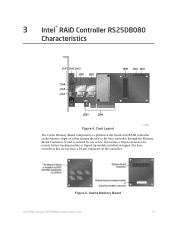
...battery backup module or SuperCap module installation support for base controllers that do not have a 20-pin connector on it that mounts directly to the base controller through the Memory Board Connector J2 and is a printed circuit board with RAID controller cache memory chips on the controller. Cache Memory Board Intel...® RAID Controller RS25DB080 Hardware User's Guide 13 Figure 5. 3 Intel® RAID Controller RS25DB080 Characteristics J1A1 J1A2 J1A3 J2B1 J2B2 J1A4 J1A5 J1A7 J5B1 J5A1 J6A1...
...battery backup module or SuperCap module installation support for base controllers that do not have a 20-pin connector on it that mounts directly to the base controller through the Memory Board Connector J2 and is a printed circuit board with RAID controller cache memory chips on the controller. Cache Memory Board Intel...® RAID Controller RS25DB080 Hardware User's Guide 13 Figure 5. 3 Intel® RAID Controller RS25DB080 Characteristics J1A1 J1A2 J1A3 J2B1 J2B2 J1A4 J1A5 J1A7 J5B1 J5A1 J6A1...

Hardware User Guide
Page 25
Jumper / Connector J5B1 J6A1 Type Board-to the memory board that contains 1GB 667MHz DDR3 memory. The memory board can be connected to an optional Intel® RAID Smart Battery AXXRSBBU9. 4-pin connector Reserved for the expander Description Provides an interface to -board Connector for the memory board UART connector for factory use. Figure 6. Hardware Block Diagram Intel® RAID Controller RS25DB080 Hardware User's Guide 15
Jumper / Connector J5B1 J6A1 Type Board-to the memory board that contains 1GB 667MHz DDR3 memory. The memory board can be connected to an optional Intel® RAID Smart Battery AXXRSBBU9. 4-pin connector Reserved for the expander Description Provides an interface to -board Connector for the memory board UART connector for factory use. Figure 6. Hardware Block Diagram Intel® RAID Controller RS25DB080 Hardware User's Guide 15

Hardware User Guide
Page 27
...). If the cause of the product may vary from the figure. The Intel® RAID Controller RS25DB080 supports Intel® RAID Smart Battery AXXRSBBU9. The ROC memory controller provides single-bit ECC error correction with multi-bit detection support. Intel® RAID Controller RS25DB080 Hardware User's Guide 17 Actual shape of failure still exists or if...
...). If the cause of the product may vary from the figure. The Intel® RAID Controller RS25DB080 supports Intel® RAID Smart Battery AXXRSBBU9. The ROC memory controller provides single-bit ECC error correction with multi-bit detection support. Intel® RAID Controller RS25DB080 Hardware User's Guide 17 Actual shape of failure still exists or if...

Hardware User Guide
Page 31
...Intel® RAID Controller RS25DB080 Hardware User's Guide 21 BBU Connector Pin-out Pin # 1 2 3 4 5 6 7 8 9 10 11 12 13 14 15 16 17 18 19 20 Name P12V GND BATT_PRSNT GND P1V8 GND P3V3 GND VBB_DDR_MEM GND P3V3_STBY GND SCL GND SDA PFAIL_L GND BBE BBSTROBE BBSTATUS Description 12V Power Ground Battery... Present Ground 1.8V Power Ground 3.3V Power Ground DDR/DDRII Power Ground 3.3V auxiliary power Ground I2C Clock Ground I2C Data Power Fail Ground Battery Backup Enabled Battery Backup Strobe Battery Backup Status I2C Connector Pin-Out ...
...Intel® RAID Controller RS25DB080 Hardware User's Guide 21 BBU Connector Pin-out Pin # 1 2 3 4 5 6 7 8 9 10 11 12 13 14 15 16 17 18 19 20 Name P12V GND BATT_PRSNT GND P1V8 GND P3V3 GND VBB_DDR_MEM GND P3V3_STBY GND SCL GND SDA PFAIL_L GND BBE BBSTROBE BBSTATUS Description 12V Power Ground Battery... Present Ground 1.8V Power Ground 3.3V Power Ground DDR/DDRII Power Ground 3.3V auxiliary power Ground I2C Clock Ground I2C Data Power Fail Ground Battery Backup Enabled Battery Backup Strobe Battery Backup Status I2C Connector Pin-Out ...

Hardware User Guide
Page 34
... Operating voltage Card size Array interface to host SAS/SATA bus speed SAS/SATA ports Physical and virtual drive support Cache Firmware Compatible devices Intel® RAID Controller RS25DB080 LSISAS2208 Integrated ROC, 800 MHz +3.3 V, +12 V 2.713 inch x 6.600 inch (Low-profile) PCI Express* Revision 2.0, x8...DDR3 667 MHz SDRAM, optional battery backup 16 MB in reflashable flash ROM • 2.5-inch and 3.5-inch SAS 2.0 or SATA III • Non disk devices including expanders • Can support drives of mixed capacity 24 Intel® RAID Controller RS25DB080 Hardware User's Guide UART ...
... Operating voltage Card size Array interface to host SAS/SATA bus speed SAS/SATA ports Physical and virtual drive support Cache Firmware Compatible devices Intel® RAID Controller RS25DB080 LSISAS2208 Integrated ROC, 800 MHz +3.3 V, +12 V 2.713 inch x 6.600 inch (Low-profile) PCI Express* Revision 2.0, x8...DDR3 667 MHz SDRAM, optional battery backup 16 MB in reflashable flash ROM • 2.5-inch and 3.5-inch SAS 2.0 or SATA III • Non disk devices including expanders • Can support drives of mixed capacity 24 Intel® RAID Controller RS25DB080 Hardware User's Guide UART ...

Hardware User Guide
Page 36
... performance of all RAID 5 logical drives simultaneously 26 Intel® RAID Controller RS25DB080 Hardware User's Guide Fault Tolerance Features Specification Self Monitoring Analysis and Reporting Technology (SMART) support Optional Battery Backup Drive Replacement Drive Rebuild Using Hot Spares Error Checking and Indication Intel® RAID Controller RS25DB080 • Detects up to the adapter via the...
... performance of all RAID 5 logical drives simultaneously 26 Intel® RAID Controller RS25DB080 Hardware User's Guide Fault Tolerance Features Specification Self Monitoring Analysis and Reporting Technology (SMART) support Optional Battery Backup Drive Replacement Drive Rebuild Using Hot Spares Error Checking and Indication Intel® RAID Controller RS25DB080 • Detects up to the adapter via the...
Hardware User Guide
Page 37
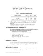
...• MTBF: greater than 300,000 hours Safety Characteristics The bare PC board shall meet or exceed the requirements of the battery pack: 250mA rise in the charging circuitry for Li-ION 2. Operating Certifications The RAID controller in this document is used in... connected the following power consumption figures apply: 1. Actual Power Consumption Table PCI Edge connector 3.3V supply +12V supply 3.3V AUX. Intel® RAID Controller RS25DB080 Hardware User's Guide 27 Supply voltage = 12V +/- 8% (from PCI edge connector only) - During fast charging of UL flammability ...
...• MTBF: greater than 300,000 hours Safety Characteristics The bare PC board shall meet or exceed the requirements of the battery pack: 250mA rise in the charging circuitry for Li-ION 2. Operating Certifications The RAID controller in this document is used in... connected the following power consumption figures apply: 1. Actual Power Consumption Table PCI Edge connector 3.3V supply +12V supply 3.3V AUX. Intel® RAID Controller RS25DB080 Hardware User's Guide 27 Supply voltage = 12V +/- 8% (from PCI edge connector only) - During fast charging of UL flammability ...