

Mechanical Design Guidelines
Page 3
... Thermal Management 9 1.1.2 Document Goals 9 1.1.3 Document Scope 10 1.2 References 11 1.3 Definition of Terms 11 2 Processor Thermal/Mechanical Information 13 2.1 Mechanical Requirements 13 2.1.1 Processor Package 13 2.1.2 Heatsink Attach 15 2.1.2.1 General Guidelines 15 2.1.2.2 Heatsink Clip Load Requirement 15 2.1.2.3 Additional Guidelines 16 2.2 Thermal Requirements 16 2.2.1 Processor Case Temperature 16 2.2.2 Thermal Profile 17 2.2.3 Thermal Solution Design Requirements 17 2.2.4 TCONTROL 18 2.3 Heatsink Design...
... Thermal Management 9 1.1.2 Document Goals 9 1.1.3 Document Scope 10 1.2 References 11 1.3 Definition of Terms 11 2 Processor Thermal/Mechanical Information 13 2.1 Mechanical Requirements 13 2.1.1 Processor Package 13 2.1.2 Heatsink Attach 15 2.1.2.1 General Guidelines 15 2.1.2.2 Heatsink Clip Load Requirement 15 2.1.2.3 Additional Guidelines 16 2.2 Thermal Requirements 16 2.2.1 Processor Case Temperature 16 2.2.2 Thermal Profile 17 2.2.3 Thermal Solution Design Requirements 17 2.2.4 TCONTROL 18 2.3 Heatsink Design...
Mechanical Design Guidelines
Page 5
... Loading 69 A.1 LGA775 Socket Heatsink Considerations 69 A.2 Metric for Heatsink Preload for ATX/uATX Designs Non-Compliant with Intel® Reference Design 69 A.3 Heatsink Preload Requirement Limitations 69 A.3.1 Motherboard Deflection Metric Definition 70 A.3.2 Board Deflection Limits... Conditions 79 Thermal Interface Management 81 C.1 Bond Line Management 81 C.2 Interface Material Area 81 C.3 Interface Material Performance 81 Case Temperature Reference Metrology 83 D.1 Objective and Scope 83 D.2 Supporting Test Equipment 83 D.3 Thermal Calibration and Controls 85 D.4 IHS Groove...
... Loading 69 A.1 LGA775 Socket Heatsink Considerations 69 A.2 Metric for Heatsink Preload for ATX/uATX Designs Non-Compliant with Intel® Reference Design 69 A.3 Heatsink Preload Requirement Limitations 69 A.3.1 Motherboard Deflection Metric Definition 70 A.3.2 Board Deflection Limits... Conditions 79 Thermal Interface Management 81 C.1 Bond Line Management 81 C.2 Interface Material Area 81 C.3 Interface Material Performance 81 Case Temperature Reference Metrology 83 D.1 Objective and Scope 83 D.2 Supporting Test Equipment 83 D.3 Thermal Calibration and Controls 85 D.4 IHS Groove...
Mechanical Design Guidelines
Page 6
...Temperature, Passive Heatsink ... 29 Figure 4-1. Effective TMA Fan Curves with Kapton* Tape Prior to Reference Clip 62 Figure 6-8. Minimum Required Processor Preload to the LGA775 Socket 88 Figure 7-16. Bottom View of the Thermocouple 90 Figure 7-18. Intel® QST Overview 64 Figure 7-2. Intel...Figure 7-17. Figures Figure 2-1. Package IHS Load Areas 13 Figure 2-2. Processor Case Temperature Measurement Location 17 Figure 2-3. Example Thermal Profile 18 Figure... and Mechanical Design Guidelines Bending the Tip of Copper Core Applied by TC-1996 Grease 52 Figure 6-3. Securing ...
...Temperature, Passive Heatsink ... 29 Figure 4-1. Effective TMA Fan Curves with Kapton* Tape Prior to Reference Clip 62 Figure 6-8. Minimum Required Processor Preload to the LGA775 Socket 88 Figure 7-16. Bottom View of the Thermocouple 90 Figure 7-18. Intel® QST Overview 64 Figure 7-2. Intel...Figure 7-17. Figures Figure 2-1. Package IHS Load Areas 13 Figure 2-2. Processor Case Temperature Measurement Location 17 Figure 2-3. Example Thermal Profile 18 Figure... and Mechanical Design Guidelines Bending the Tip of Copper Core Applied by TC-1996 Grease 52 Figure 6-3. Securing ...
Mechanical Design Guidelines
Page 7
... 7-51. Reference Fastener - Sheet 2 121 Figure 7-52. Sheet 4 123 Figure 7-54. Heatsink Inlet Temperature of Accelerant 100 Figure 7-35. Processor Preload Limits 49 Table 6-1. E18764-001 Reference Heatsink Performance 53 Table 6-2. Board Deflection Configuration Definitions 70 Table...115 Figure 7-46. Reference Fastener - Intel® E18764-001 Reference Solution Assembly 124 Tables Table 2-1. BTX Thermal Module Keep Out Volumetric - Intel® Representative Contact for Licensing Information of Intel® Boxed Processor Thermal Solutions.22 Table 5-1. VR Airflow ...
... 7-51. Reference Fastener - Sheet 2 121 Figure 7-52. Sheet 4 123 Figure 7-54. Heatsink Inlet Temperature of Accelerant 100 Figure 7-35. Processor Preload Limits 49 Table 6-1. E18764-001 Reference Heatsink Performance 53 Table 6-2. Board Deflection Configuration Definitions 70 Table...115 Figure 7-46. Reference Fastener - Intel® E18764-001 Reference Solution Assembly 124 Tables Table 2-1. BTX Thermal Module Keep Out Volumetric - Intel® Representative Contact for Licensing Information of Intel® Boxed Processor Thermal Solutions.22 Table 5-1. VR Airflow ...
Mechanical Design Guidelines
Page 9
... temperature range. As operating frequencies increase and packaging size decreases, the power density increases while the thermal solution space and airflow typically become more transistors). The concepts given in particular on single processor systems using the Intel® Core™2 Duo processor E8000, E7000 series, Intel® Pentium® dual-core processor E6000, E5000 series, and Intel® Celeron® processor...
... temperature range. As operating frequencies increase and packaging size decreases, the power density increases while the thermal solution space and airflow typically become more transistors). The concepts given in particular on single processor systems using the Intel® Core™2 Duo processor E8000, E7000 series, Intel® Pentium® dual-core processor E6000, E5000 series, and Intel® Celeron® processor...
Mechanical Design Guidelines
Page 10
... guide supports the following processors: • Intel® Core™2 Duo processor E8000 series with 6 MB cache applies to Intel® Core™2 Duo processors E8600, E8500, E8400, E8300, E8200, and E8190 • Intel® Core™2 Duo processor E7000 series with 3 MB cache applies to Intel® Core™2 Duo processors E7600, E7500, E7400, E7300, and E7200 • Intel® Pentium® dual-core processor E5000 series with 2 MB...
... guide supports the following processors: • Intel® Core™2 Duo processor E8000 series with 6 MB cache applies to Intel® Core™2 Duo processors E8600, E8500, E8400, E8300, E8200, and E8190 • Intel® Core™2 Duo processor E7000 series with 3 MB cache applies to Intel® Core™2 Duo processors E7600, E7500, E7400, E7300, and E7200 • Intel® Pentium® dual-core processor E5000 series with 2 MB...

Mechanical Design Guidelines
Page 11
... heatsink or at the fan inlet for an active heatsink. This temperature is defined as specified in a component specification. Document Intel® Core™2 Duo Processor E8000 and E7000 Series Datasheet Intel® Pentium® Dual-Core Processor E6000 and E5000 Series Datasheet Intel® Celeron® Processor E3000 Series Datasheet LGA775 Socket Mechanical Design Guide uATX SFF Design Guidance...
... heatsink or at the fan inlet for an active heatsink. This temperature is defined as specified in a component specification. Document Intel® Core™2 Duo Processor E8000 and E7000 Series Datasheet Intel® Pentium® Dual-Core Processor E6000 and E5000 Series Datasheet Intel® Celeron® Processor E3000 Series Datasheet LGA775 Socket Mechanical Design Guide uATX SFF Design Guidance...

Mechanical Design Guidelines
Page 12
...package power. Integrated Heat Spreader: a thermally conductive lid integrated into a processor package to improve heat transfer to reduce die temperature by lowering the effective processor frequency when the die temperature has exceeded its operating limits. The enabled 4-wire fans use with the ... of the PWM signal. Thermal Design Power: a power dissipation target based on -die thermal diode. Digital Thermal Sensor: Processor die sensor temperature defined as a reference to the 4-pin fan header. Thermal Control Circuit: Thermal Monitor uses the TCC to a thermal solution...
...package power. Integrated Heat Spreader: a thermally conductive lid integrated into a processor package to improve heat transfer to reduce die temperature by lowering the effective processor frequency when the die temperature has exceeded its operating limits. The enabled 4-wire fans use with the ... of the PWM signal. Thermal Design Power: a power dissipation target based on -die thermal diode. Digital Thermal Sensor: Processor die sensor temperature defined as a reference to the 4-pin fan header. Thermal Control Circuit: Thermal Monitor uses the TCC to a thermal solution...

Mechanical Design Guidelines
Page 15
... to Appendix B. One of the strategies for the heatsink developed to Appendix A. Designs should consider a possible decrease in temperature cycling. It is implemented by the LGA775 socket load plate (refer to the LGA775 Socket Mechanical Design Guide for further ... is implemented, in retention components. • Ensuring system electrical, thermal, and structural integrity under shock and vibration events. Processor Thermal/Mechanical Information 2.1.2 Heatsink Attach 2.1.2.1 General Guidelines There are no board stiffening device (backing plate, chassis attach, and so...
... to Appendix B. One of the strategies for the heatsink developed to Appendix A. Designs should consider a possible decrease in temperature cycling. It is implemented by the LGA775 socket load plate (refer to the LGA775 Socket Mechanical Design Guide for further ... is implemented, in retention components. • Ensuring system electrical, thermal, and structural integrity under shock and vibration events. Processor Thermal/Mechanical Information 2.1.2 Heatsink Attach 2.1.2.1 General Guidelines There are no board stiffening device (backing plate, chassis attach, and so...

Mechanical Design Guidelines
Page 16
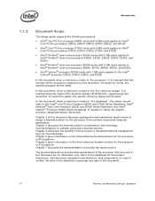
...should be installed after reflow, given in the LGA775 Socket Mechanical Design Guide with a 28.7 mm x 28.7 mm [1.13 in x 1.13 in place under mechanical shock and vibration events and applies force to the heatsink base to maintain desired pressure on the ...no additional components (such as the temperature measured at the geometric center of the IHS. Processor Case Temperature For the processor, the case temperature is dissipated through the processor package substrate and into the chassis. • Minimizes contact with the temperature reported by the heatsink attach mechanism ...
...should be installed after reflow, given in the LGA775 Socket Mechanical Design Guide with a 28.7 mm x 28.7 mm [1.13 in x 1.13 in place under mechanical shock and vibration events and applies force to the heatsink base to maintain desired pressure on the ...no additional components (such as the temperature measured at the geometric center of the IHS. Processor Case Temperature For the processor, the case temperature is dissipated through the processor package substrate and into the chassis. • Minimizes contact with the temperature reported by the heatsink attach mechanism ...
Mechanical Design Guidelines
Page 17
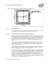
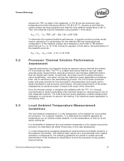
...design based on its improvement is about 15% over the Intel reference design (E18764-001). For an example of Intel Core™2 Duo processor E8000 series with 6 MB in thermal solution performance of the Intel reference design. The intercept on the thermal profile and can... thermal profile assumes a maximum ambient operating condition that are targeted to Section 3.1). Processor Case Temperature Measurement Location Measure TC at an inlet temperature of processor power dissipation. Refer to manage the processor TDP at this point (geometric center of the package) 37.5 mm 37.5 ...
...design based on its improvement is about 15% over the Intel reference design (E18764-001). For an example of Intel Core™2 Duo processor E8000 series with 6 MB in thermal solution performance of the Intel reference design. The intercept on the thermal profile and can... thermal profile assumes a maximum ambient operating condition that are targeted to Section 3.1). Processor Case Temperature Measurement Location Measure TC at an inlet temperature of processor power dissipation. Refer to manage the processor TDP at this point (geometric center of the package) 37.5 mm 37.5 ...
Mechanical Design Guidelines
Page 18
... TDP 40 0 10 20 30 40 50 60 70 Power (W) 2.2.4 TCONTROL TCONTROL defines the maximum operating temperature for the digital thermal sensor when the thermal solution fan speed is driven by the digital thermal sensor. See... of the 775_VR_CONFIG_06 processors. Processor Thermal/Mechanical Information The thermal profiles for the Intel Core™2 Duo processor E8000 series with 6 MB cache, Intel Core™2 Duo processor E7000 series with 3 MB cache, and Intel Pentium dual-core processor E6000 and E5000 series with 2 MB cache, and Intel Celeron processor E3000 series with lower...
... TDP 40 0 10 20 30 40 50 60 70 Power (W) 2.2.4 TCONTROL TCONTROL defines the maximum operating temperature for the digital thermal sensor when the thermal solution fan speed is driven by the digital thermal sensor. See... of the 775_VR_CONFIG_06 processors. Processor Thermal/Mechanical Information The thermal profiles for the Intel Core™2 Duo processor E8000 series with 6 MB cache, Intel Core™2 Duo processor E7000 series with 3 MB cache, and Intel Pentium dual-core processor E6000 and E5000 series with 2 MB cache, and Intel Celeron processor E3000 series with lower...

Mechanical Design Guidelines
Page 19
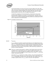
...source to program a fan speed control component. Providing a direct conduction path from the processor, three basic parameters should be used to the heatsink fins and selecting materials with potentially ...the heatsink fins. Typically, passive heatsinks see lower air speed. See Chapter 7, Intel® Quiet System Technology (Intel® QST), for TCONTROL is calculated by the system BIOS based on which...heatsink solutions require in-depth knowledge of the airflow in part by the local ambient temperature of a heatsink, the surface exposed to the flow includes in the gap between ...
...source to program a fan speed control component. Providing a direct conduction path from the processor, three basic parameters should be used to the heatsink fins and selecting materials with potentially ...the heatsink fins. Typically, passive heatsinks see lower air speed. See Chapter 7, Intel® Quiet System Technology (Intel® QST), for TCONTROL is calculated by the system BIOS based on which...heatsink solutions require in-depth knowledge of the airflow in part by the local ambient temperature of a heatsink, the surface exposed to the flow includes in the gap between ...
Mechanical Design Guidelines
Page 22
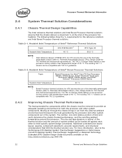
...;C. The existing TAC 1.1 chassis can be removed to Thermally Advantaged Chassis (TAC) Design Guide for Intel® Core™2 Duo Processor E8000, E7000 Series, Intel® Pentium® Dual-Core Processor E6000, E5000 Series, and Intel® Celeron® Processor E3000 Series Heatsink Inlet Temperature 40 °C NOTE: 1. Table 2-2. The size and type (passive or active) of the thermal solution...
...;C. The existing TAC 1.1 chassis can be removed to Thermally Advantaged Chassis (TAC) Design Guide for Intel® Core™2 Duo Processor E8000, E7000 Series, Intel® Pentium® Dual-Core Processor E6000, E5000 Series, and Intel® Celeron® Processor E3000 Series Heatsink Inlet Temperature 40 °C NOTE: 1. Table 2-2. The size and type (passive or active) of the thermal solution...
Mechanical Design Guidelines
Page 23
...flatness and roughness. • The performance of the thermal interface material used in heatsink design include: • The local ambient temperature TA at the entire system level, accounting for further information. § Thermal and Mechanical Design Guidelines 23 More information on ...all capable of these solutions may limit the size, number, placement, and types of the processor. Thermal Monitor attempts to air thermal characterization parameter). Contact your Intel field sales representative for the thermal requirements of each of dissipating additional heat. A video ...
...flatness and roughness. • The performance of the thermal interface material used in heatsink design include: • The local ambient temperature TA at the entire system level, accounting for further information. § Thermal and Mechanical Design Guidelines 23 More information on ...all capable of these solutions may limit the size, number, placement, and types of the processor. Thermal Monitor attempts to air thermal characterization parameter). Contact your Intel field sales representative for the thermal requirements of each of dissipating additional heat. A video ...

Mechanical Design Guidelines
Page 25
...thermal characterization parameter (°C/W) TC = Processor case temperature (°C) TA = Local ambient temperature in chassis at processor (°C) PD = Processor total power dissipation (W) (assumes all cases, the thermal engineer must measure power dissipation and temperature to compare thermal solutions in units of ...case-to-local ambient thermal characterization parameter of the processor, ΨCA, is a convenient way to characterize the performance needed for testing thermal solutions, including measuring processor temperatures. Note: Heat transfer is a three-dimensional ...
...thermal characterization parameter (°C/W) TC = Processor case temperature (°C) TA = Local ambient temperature in chassis at processor (°C) PD = Processor total power dissipation (W) (assumes all cases, the thermal engineer must measure power dissipation and temperature to compare thermal solutions in units of ...case-to-local ambient thermal characterization parameter of the processor, ΨCA, is a convenient way to characterize the performance needed for testing thermal solutions, including measuring processor temperatures. Note: Heat transfer is a three-dimensional ...

Mechanical Design Guidelines
Page 26
... the combination of thermal characterization parameter described above: • The case temperature TC-MAX and thermal design power TDP given in the processor datasheet. • Define a target local ambient temperature at the processor, TA. Figure 3-1. Thermal Metrology ΨSA is a measure of the... thermal characterization parameter from the bottom of the heatsink to any specific Intel processor thermal specifications, and ...
... the combination of thermal characterization parameter described above: • The case temperature TC-MAX and thermal design power TDP given in the processor datasheet. • Define a target local ambient temperature at the processor, TA. Figure 3-1. Thermal Metrology ΨSA is a measure of the... thermal characterization parameter from the bottom of the heatsink to any specific Intel processor thermal specifications, and ...
Mechanical Design Guidelines
Page 27
... the thermal solution is the temperature of the thermal solution on real processors and on fully integrated systems. The Intel maximum power application enables steady power dissipation on the case temperature. Local Ambient Temperature Measurement Guidelines The local ambient temperature TA is best measured by Intel, due to determine the local ambient temperature in the manufacturing process. TA...
... the thermal solution is the temperature of the thermal solution on real processors and on fully integrated systems. The Intel maximum power application enables steady power dissipation on the case temperature. Local Ambient Temperature Measurement Guidelines The local ambient temperature TA is best measured by Intel, due to determine the local ambient temperature in the manufacturing process. TA...

Mechanical Design Guidelines
Page 28
... potential impact of the thermal solution. Otherwise, when doing a bench top test at room temperature, the fan regulation prevents the heatsink from the fan supplier. 28 Thermal and Mechanical Design...the worst-case thermal environment scenarios. For passive heatsinks, thermocouples should be placed approximately 13 mm to 25 mm [0.5 to the barrier above the baseboard. Thermal Metrology For ... Measurements should be taped directly to evaluate the uniformity of localized hot spots from processor and heatsink as shown in the ATX heatsink in all directions beyond the edge ...
... potential impact of the thermal solution. Otherwise, when doing a bench top test at room temperature, the fan regulation prevents the heatsink from the fan supplier. 28 Thermal and Mechanical Design...the worst-case thermal environment scenarios. For passive heatsinks, thermocouples should be placed approximately 13 mm to 25 mm [0.5 to the barrier above the baseboard. Thermal Metrology For ... Measurements should be taped directly to evaluate the uniformity of localized hot spots from processor and heatsink as shown in the ATX heatsink in all directions beyond the edge ...

Mechanical Design Guidelines
Page 29
Locations for Measuring Local Ambient Temperature, Active ATX Heatsink Note: Drawing Not to Scale Thermal and Mechanical Design Guidelines 29 Thermal Metrology Figure 3-2. Locations for Measuring Local Ambient Temperature, Passive Heatsink Note: Drawing Not to Scale Figure 3-3.
Locations for Measuring Local Ambient Temperature, Active ATX Heatsink Note: Drawing Not to Scale Thermal and Mechanical Design Guidelines 29 Thermal Metrology Figure 3-2. Locations for Measuring Local Ambient Temperature, Passive Heatsink Note: Drawing Not to Scale Figure 3-3.