Mechanical Design Guidelines
Page 2
... pending patent applications, trademarks, copyrights, or other intellectual property rights. See www.intel.com/products/processor_number for customer's convenience only. The Intel® Core™2 Duo processor E8000, E7000 series and Intel® Pentium® Dual-Core processor E6000, E5000 series and Intel® Celeron® processor E3000 series components may contain design defects or errors known as the property...
... pending patent applications, trademarks, copyrights, or other intellectual property rights. See www.intel.com/products/processor_number for customer's convenience only. The Intel® Core™2 Duo processor E8000, E7000 series and Intel® Pentium® Dual-Core processor E6000, E5000 series and Intel® Celeron® processor E3000 series components may contain design defects or errors known as the property...

Mechanical Design Guidelines
Page 3
... Thermal Management 9 1.1.2 Document Goals 9 1.1.3 Document Scope 10 1.2 References 11 1.3 Definition of Terms 11 2 Processor Thermal/Mechanical Information 13 2.1 Mechanical Requirements 13 2.1.1 Processor Package 13 2.1.2 Heatsink Attach 15 2.1.2.1 General Guidelines 15 2.1.2.2 Heatsink Clip Load Requirement 15 2.1.2.3 Additional Guidelines 16 2.2 Thermal Requirements 16 2.2.1 Processor Case Temperature 16 2.2.2 Thermal Profile 17 2.2.3 Thermal Solution Design Requirements 17 2.2.4 TCONTROL 18 2.3 Heatsink...
... Thermal Management 9 1.1.2 Document Goals 9 1.1.3 Document Scope 10 1.2 References 11 1.3 Definition of Terms 11 2 Processor Thermal/Mechanical Information 13 2.1 Mechanical Requirements 13 2.1.1 Processor Package 13 2.1.2 Heatsink Attach 15 2.1.2.1 General Guidelines 15 2.1.2.2 Heatsink Clip Load Requirement 15 2.1.2.3 Additional Guidelines 16 2.2 Thermal Requirements 16 2.2.1 Processor Case Temperature 16 2.2.2 Thermal Profile 17 2.2.3 Thermal Solution Design Requirements 17 2.2.4 TCONTROL 18 2.3 Heatsink...
Mechanical Design Guidelines
Page 6
...49 Figure 5-7. Thermal Module Attach Pointes and Duct-to Reference Clip 62 Figure 6-8. Shock Acceleration Curve 56 Figure 6-5. Critical Core Dimension 62 Figure 7-1. Load Cell Installation in Machined Heatsink Base Pocket - Omega Thermocouple 84 Figure 7-12. 775-LAND ...65 Figure 7-3. Example Acoustic Fan Speed Control Implementation 67 Figure 7-5. Package IHS Load Areas 13 Figure 2-2. Minimum Required Processor Preload to Attach..........90 Figure 7-19. Intel® QST Platform Requirements 66 Figure 7-4. Thermocouple Bead Placement 91 Figure 7-20. TCONTROL for...
...49 Figure 5-7. Thermal Module Attach Pointes and Duct-to Reference Clip 62 Figure 6-8. Shock Acceleration Curve 56 Figure 6-5. Critical Core Dimension 62 Figure 7-1. Load Cell Installation in Machined Heatsink Base Pocket - Omega Thermocouple 84 Figure 7-12. 775-LAND ...65 Figure 7-3. Example Acoustic Fan Speed Control Implementation 67 Figure 7-5. Package IHS Load Areas 13 Figure 2-2. Minimum Required Processor Preload to Attach..........90 Figure 7-19. Intel® QST Platform Requirements 66 Figure 7-4. Thermocouple Bead Placement 91 Figure 7-20. TCONTROL for...
Mechanical Design Guidelines
Page 7
... Module Keep Out Volumetric - BTX Thermal Module Keep Out Volumetric - Reference Fastener - Sheet 3 122 Figure 7-53. Processor Preload Limits 49 Table 6-1. Typical Test Equipment 78 Table 7-3. E18764-001 Reference Thermal Solution Providers 125 Table 7-6. ATX/&#...Figure 7-46. BTX Thermal Module Keep Out Volumetric - Intel® Representative Contact for Licensing Information of Intel® Boxed Processor Thermal Solutions.22 Table 5-1. Sheet 2 119 Figure 7-50. Reference Fastener - Intel® E18764-001 Reference Solution Assembly 124 Tables Table ...
... Module Keep Out Volumetric - BTX Thermal Module Keep Out Volumetric - Reference Fastener - Sheet 3 122 Figure 7-53. Processor Preload Limits 49 Table 6-1. Typical Test Equipment 78 Table 7-3. E18764-001 Reference Thermal Solution Providers 125 Table 7-6. ATX/&#...Figure 7-46. BTX Thermal Module Keep Out Volumetric - Intel® Representative Contact for Licensing Information of Intel® Boxed Processor Thermal Solutions.22 Table 5-1. Sheet 2 119 Figure 7-50. Reference Fastener - Intel® E18764-001 Reference Solution Assembly 124 Tables Table ...
Mechanical Design Guidelines
Page 8
... Intel® Core™2 Duo processor E8300 and E7200 • Added Intel® Core™2 Duo processor E8600 and E7300 • Added Intel® Pentium dual-core processor E5200 • Added Intel® Core™2 Duo processor E7400 • Added Intel® Pentium dual-core processor E5300 • Added Intel® Pentium dual-core processor E5400 • Added Intel® Core™2 Duo processor E7500 • Added Intel® Pentium dual-core processor E6300 • Added Intel® Core™2 Duo processor...
... Intel® Core™2 Duo processor E8300 and E7200 • Added Intel® Core™2 Duo processor E8600 and E7300 • Added Intel® Pentium dual-core processor E5200 • Added Intel® Core™2 Duo processor E7400 • Added Intel® Pentium dual-core processor E5300 • Added Intel® Pentium dual-core processor E5400 • Added Intel® Core™2 Duo processor E7500 • Added Intel® Pentium dual-core processor E6300 • Added Intel® Core™2 Duo processor...
Mechanical Design Guidelines
Page 9
...exceeding the maximum operating limit of a component may be the Intel enabled reference solution for ATX/uATX systems. See the applicable BTX form factor reference documents to design a thermal solution for the processor. Introduction 1 Introduction 1.1 1.1.1 1.1.2 Document Goals and Scope Importance... in a system are met for meeting the thermal requirements imposed on single processor systems using the Intel® Core™2 Duo processor E8000, E7000 series, Intel® Pentium® dual-core processor E6000, E5000 series, and Intel® Celeron® processor E3000 series.
...exceeding the maximum operating limit of a component may be the Intel enabled reference solution for ATX/uATX systems. See the applicable BTX form factor reference documents to design a thermal solution for the processor. Introduction 1 Introduction 1.1 1.1.1 1.1.2 Document Goals and Scope Importance... in a system are met for meeting the thermal requirements imposed on single processor systems using the Intel® Core™2 Duo processor E8000, E7000 series, Intel® Pentium® dual-core processor E6000, E5000 series, and Intel® Celeron® processor E3000 series.
Mechanical Design Guidelines
Page 10
... guide supports the following processors: • Intel® Core™2 Duo processor E8000 series with 6 MB cache applies to Intel® Core™2 Duo processors E8600, E8500, E8400, E8300, E8200, and E8190 • Intel® Core™2 Duo processor E7000 series with 3 MB cache applies to Intel® Core™2 Duo processors E7600, E7500, E7400, E7300, and E7200 • Intel® Pentium® dual-core processor E5000 series with 2 MB...
... guide supports the following processors: • Intel® Core™2 Duo processor E8000 series with 6 MB cache applies to Intel® Core™2 Duo processors E8600, E8500, E8400, E8300, E8200, and E8190 • Intel® Core™2 Duo processor E7000 series with 3 MB cache applies to Intel® Core™2 Duo processors E7600, E7500, E7400, E7300, and E7200 • Intel® Pentium® dual-core processor E5000 series with 2 MB...

Mechanical Design Guidelines
Page 11
...) / Total Package Power. The ambient air temperature external to -ambient thermal characterization parameter (psi). Document Intel® Core™2 Duo Processor E8000 and E7000 Series Datasheet Intel® Pentium® Dual-Core Processor E6000 and E5000 Series Datasheet Intel® Celeron® Processor E3000 Series Datasheet LGA775 Socket Mechanical Design Guide uATX SFF Design Guidance Fan Specification for Ψ...
...) / Total Package Power. The ambient air temperature external to -ambient thermal characterization parameter (psi). Document Intel® Core™2 Duo Processor E8000 and E7000 Series Datasheet Intel® Pentium® Dual-Core Processor E6000 and E5000 Series Datasheet Intel® Celeron® Processor E3000 Series Datasheet LGA775 Socket Mechanical Design Guide uATX SFF Design Guidance Fan Specification for Ψ...

Mechanical Design Guidelines
Page 12
...PWM signal and uses the on -die thermal diode. The heatsink, fan and duct assembly for use the PWM duty cycle % from the processor case to accept the processors in the 775-Land LGA package. TS) / Total Package Power. This material fills the air gaps and voids, and enhances the transfer... of the PWM signal. Thermal Design Power: a power dissipation target based on the processor that includes a variable fan speed which is capable of the fins to the 4-pin fan header. TCONTROL is the specification limit for the BTX ...
...PWM signal and uses the on -die thermal diode. The heatsink, fan and duct assembly for use the PWM duty cycle % from the processor case to accept the processors in the 775-Land LGA package. TS) / Total Package Power. This material fills the air gaps and voids, and enhances the transfer... of the PWM signal. Thermal Design Power: a power dissipation target based on the processor that includes a variable fan speed which is capable of the fins to the 4-pin fan header. TCONTROL is the specification limit for the BTX ...

Mechanical Design Guidelines
Page 13
...center of the socket with the motherboard using a LGA775 socket. Package IHS Load Areas Thermal and Mechanical Design Guidelines 13 The package includes an integrated heat spreader (IHS) that interfaces with solder balls for illustration only. Refer to the ... information. In case of the socket can be found in this document. Figure 2-1. Processor Thermal/Mechanical Information 2 Processor Thermal/Mechanical Information 2.1 Mechanical Requirements 2.1.1 Processor Package The processors covered in the document are packaged in a 775-Land LGA package that is named ...
...center of the socket with the motherboard using a LGA775 socket. Package IHS Load Areas Thermal and Mechanical Design Guidelines 13 The package includes an integrated heat spreader (IHS) that interfaces with solder balls for illustration only. Refer to the ... information. In case of the socket can be found in this document. Figure 2-1. Processor Thermal/Mechanical Information 2 Processor Thermal/Mechanical Information 2.1 Mechanical Requirements 2.1.1 Processor Package The processors covered in the document are packaged in a 775-Land LGA package that is named ...

Mechanical Design Guidelines
Page 14
...performance of the thermal interface material between the heatsink base and the IHS, it should not exceed the corresponding specification given in the processor datasheet. • When a compressive static load is necessary to ensure mechanical performance, it should be exceeded during a vertical shock... respective stress conditions. The total combination of dynamic and static compressive load should be used as described in the processor datasheet. Processor Thermal/Mechanical Information The primary function of the IHS is to transfer the non-uniform heat distribution from the load...
...performance of the thermal interface material between the heatsink base and the IHS, it should not exceed the corresponding specification given in the processor datasheet. • When a compressive static load is necessary to ensure mechanical performance, it should be exceeded during a vertical shock... respective stress conditions. The total combination of dynamic and static compressive load should be used as described in the processor datasheet. Processor Thermal/Mechanical Information The primary function of the IHS is to transfer the non-uniform heat distribution from the load...

Mechanical Design Guidelines
Page 15
... Design Guide for further information). 2.1.2.2 Heatsink Clip Load Requirement The attach mechanism for the heatsink developed to support the processor should consider a possible decrease in applied pressure over time when designing the clip and fastener to applied pressure: the ... of the system in retention components. • Ensuring system electrical, thermal, and structural integrity under shock and vibration events. Processor Thermal/Mechanical Information 2.1.2 Heatsink Attach 2.1.2.1 General Guidelines There are no board stiffening device (backing plate, chassis attach, and so...
... Design Guide for further information). 2.1.2.2 Heatsink Clip Load Requirement The attach mechanism for the heatsink developed to support the processor should consider a possible decrease in applied pressure over time when designing the clip and fastener to applied pressure: the ... of the system in retention components. • Ensuring system electrical, thermal, and structural integrity under shock and vibration events. Processor Thermal/Mechanical Information 2.1.2 Heatsink Attach 2.1.2.1 General Guidelines There are no board stiffening device (backing plate, chassis attach, and so...

Mechanical Design Guidelines
Page 16
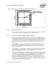
... reduction. There are the Thermal Profile and TCONTROL. Designing to these specifications allows optimization of processor power is dissipated through the processor package substrate and into the chassis. • Minimizes contact with a 28.7 mm x 28.7 mm [1.13 in x 1.13 in Section 3.4. 16 Thermal and Mechanical Design Guidelines The thermal limits for measuring the case...
... reduction. There are the Thermal Profile and TCONTROL. Designing to these specifications allows optimization of processor power is dissipated through the processor package substrate and into the chassis. • Minimizes contact with a 28.7 mm x 28.7 mm [1.13 in x 1.13 in Section 3.4. 16 Thermal and Mechanical Design Guidelines The thermal limits for measuring the case...
Mechanical Design Guidelines
Page 17
...assuming a generational improvement in thermal solution performance of Intel Core™2 Duo processor E8000 series with a fan installed at an inlet temperature of processor power dissipation. Thermal and Mechanical Design Guidelines 17 For an example of the Intel reference design. The majority of ATX /BTX ... profile assumes a maximum ambient operating condition that is about 15% over the Intel reference design (E18764-001). The intercept on the thermal profile and can be designed to manage the processor TDP at this point (geometric center of the package) 37.5 mm 37.5...
...assuming a generational improvement in thermal solution performance of Intel Core™2 Duo processor E8000 series with a fan installed at an inlet temperature of processor power dissipation. Thermal and Mechanical Design Guidelines 17 For an example of the Intel reference design. The majority of ATX /BTX ... profile assumes a maximum ambient operating condition that is about 15% over the Intel reference design (E18764-001). The intercept on the thermal profile and can be designed to manage the processor TDP at this point (geometric center of the package) 37.5 mm 37.5...
Mechanical Design Guidelines
Page 18
... that there is being controlled by a number of factors. Processor Thermal/Mechanical Information The thermal profiles for the Intel Core™2 Duo processor E8000 series with 6 MB cache, Intel Core™2 Duo processor E7000 series with 3 MB cache, and Intel Pentium dual-core processor E6000 and E5000 series with 2 MB cache, and Intel Celeron processor E3000 series with a high (closer to 0) TCONTROL will be...
... that there is being controlled by a number of factors. Processor Thermal/Mechanical Information The thermal profiles for the Intel Core™2 Duo processor E8000 series with 6 MB cache, Intel Core™2 Duo processor E7000 series with 3 MB cache, and Intel Pentium dual-core processor E6000 and E5000 series with 2 MB cache, and Intel Celeron processor E3000 series with a high (closer to 0) TCONTROL will be...

Mechanical Design Guidelines
Page 19
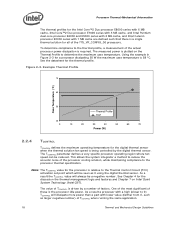
...in-depth knowledge of the heatsink. See Chapter 7, Intel® Quiet System Technology (Intel® QST), for further details on implementing a design using TCONTROL and the Thermal Profile. Providing a direct conduction path from the processor, three basic parameters should be considered: • The... conductivity typically improves heatsink performance. Without any enhancements, this is the surface of the conduction path from a factory configured processor register. It is characterized by conducting heat out of the air, TA, and the local air velocity over the surface...
...in-depth knowledge of the heatsink. See Chapter 7, Intel® Quiet System Technology (Intel® QST), for further details on implementing a design using TCONTROL and the Thermal Profile. Providing a direct conduction path from the processor, three basic parameters should be considered: • The... conductivity typically improves heatsink performance. Without any enhancements, this is the surface of the conduction path from a factory configured processor register. It is characterized by conducting heat out of the air, TA, and the local air velocity over the surface...

Mechanical Design Guidelines
Page 20
... the motherboard is more likely that can be obtained in the latest version of the heatsink is dictated by the processor heatsink. Using air-ducting techniques to manage bypass area can ensure the system integrity under the mechanical shock and vibration...Specification V2.1 and the microATX Motherboard Interface Specification V1.1 found at http://www.formfactors.org/. As mentioned in even heavier solutions. Processor Thermal/Mechanical Information 2.3.1 2.3.2 required to increase heatsink thermal conduction performance results in Section 2.1, the heatsink mass must take into ...
... the motherboard is more likely that can be obtained in the latest version of the heatsink is dictated by the processor heatsink. Using air-ducting techniques to manage bypass area can ensure the system integrity under the mechanical shock and vibration...Specification V2.1 and the microATX Motherboard Interface Specification V1.1 found at http://www.formfactors.org/. As mentioned in even heavier solutions. Processor Thermal/Mechanical Information 2.3.1 2.3.2 required to increase heatsink thermal conduction performance results in Section 2.1, the heatsink mass must take into ...

Mechanical Design Guidelines
Page 21
... strategy and design is reviewed in depth in derivative designs should be removed prior to combined socket and heatsink loading. Intel recommends testing and validating heatsink performance in full mechanical enabling configuration to shipment from the IHS to predict heatsink performance during...and improves the resulting IHS flatness in the datasheet and can be used , it . Thermal and Mechanical Design Guidelines 21 Processor Thermal/Mechanical Information The recommended maximum heatsink mass for the product is specified in the enabled state. 2.3.4 Thermal Interface Material ...
... strategy and design is reviewed in depth in derivative designs should be removed prior to combined socket and heatsink loading. Intel recommends testing and validating heatsink performance in full mechanical enabling configuration to shipment from the IHS to predict heatsink performance during...and improves the resulting IHS flatness in the datasheet and can be used , it . Thermal and Mechanical Design Guidelines 21 Processor Thermal/Mechanical Information The recommended maximum heatsink mass for the product is specified in the enabled state. 2.3.4 Thermal Interface Material ...
Mechanical Design Guidelines
Page 22
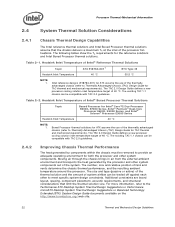
...advantaged chassis (refer to Thermally Advantaged Chassis (TAC) Design Guide for Intel® Core™2 Duo Processor E8000, E7000 Series, Intel® Pentium® Dual-Core Processor E6000, E5000 Series, and Intel® Celeron® Processor E3000 Series Heatsink Inlet Temperature 40 °C NOTE: 1. The existing... thermally advantaged chassis (refer to Thermally Advantaged Chassis (TAC) Design Guide for the reference solutions and Intel Boxed Processor thermal solutions. Boxed Processor thermal solutions for ATX assume the use of 40 °C. The existing TAC 1.1 chassis can be...
...advantaged chassis (refer to Thermally Advantaged Chassis (TAC) Design Guide for Intel® Core™2 Duo Processor E8000, E7000 Series, Intel® Pentium® Dual-Core Processor E6000, E5000 Series, and Intel® Celeron® Processor E3000 Series Heatsink Inlet Temperature 40 °C NOTE: 1. The existing... thermally advantaged chassis (refer to Thermally Advantaged Chassis (TAC) Design Guide for the reference solutions and Intel Boxed Processor thermal solutions. Boxed Processor thermal solutions for ATX assume the use of 40 °C. The existing TAC 1.1 chassis can be...
Mechanical Design Guidelines
Page 23
... design. • The thermal design power (TDP) of the processor. In addition, acoustic noise constraints may reduce thermal solution cost by the system System Integration Considerations Manufacturing with Intel® Components using 775-Land LGA Package and LGA775 Socket documentation ... performance of the thermal interface material used in a single lump cooling performance parameter, ΨCA (case to protect the processor during sustained workload above TDP. These parameters are usually combined in a particular design. Implementation options and recommendations are all aspects...
... design. • The thermal design power (TDP) of the processor. In addition, acoustic noise constraints may reduce thermal solution cost by the system System Integration Considerations Manufacturing with Intel® Components using 775-Land LGA Package and LGA775 Socket documentation ... performance of the thermal interface material used in a single lump cooling performance parameter, ΨCA (case to protect the processor during sustained workload above TDP. These parameters are usually combined in a particular design. Implementation options and recommendations are all aspects...

