
User Guide
Page 1
R Intel® Pentium® 4 Processor on 90 nm Process in the 775-Land LGA Package Thermal and Mechanical Design Guidelines Supporting Intel® Pentium® 4 Processor 5xx and 6xx Sequences in the 775-land LGA Package and Intel® Pentium® 4 Processor Extreme Edition in the 775-land LGA Package November 2005 Document Number: 302553-004
R Intel® Pentium® 4 Processor on 90 nm Process in the 775-Land LGA Package Thermal and Mechanical Design Guidelines Supporting Intel® Pentium® 4 Processor 5xx and 6xx Sequences in the 775-land LGA Package and Intel® Pentium® 4 Processor Extreme Edition in the 775-land LGA Package November 2005 Document Number: 302553-004
User Guide
Page 2
... that relate to the presented subject matter. The furnishing of Intel Corporation or its subsidiaries in nuclear facility applications. Performance will not operate (including 32-bit operation) without an Intel EM64T-enabled BIOS. Intel accepts no representations or warranties regarding the accuracy or completeness of...; 4 Processor in the 775-Land LGA Package may contain design defects or errors known as errata, which processors support Intel EM64T or consult with a processor, chipset, BIOS, operating system, device drivers and applications enabled for results if customer chooses...
... that relate to the presented subject matter. The furnishing of Intel Corporation or its subsidiaries in nuclear facility applications. Performance will not operate (including 32-bit operation) without an Intel EM64T-enabled BIOS. Intel accepts no representations or warranties regarding the accuracy or completeness of...; 4 Processor in the 775-Land LGA Package may contain design defects or errors known as errata, which processors support Intel EM64T or consult with a processor, chipset, BIOS, operating system, device drivers and applications enabled for results if customer chooses...
User Guide
Page 5
...C.2 Interface Material Area 73 C.3 Interface Material Performance 73 Appendix D Case Temperature Reference Metrology 75 D.1 Objective and Scope 75 D.2 Definitions...75 D.3 Supporting Test Equipment 76 D.4 Thermal Calibration and Controls 77 D.5 IHS Groove...77 D.6 Thermocouple Attach Procedure 80 D.6.1 Thermocouple Conditioning and Preparation 80 D.6.2 Thermocouple... 87 Appendix F Balanced Technology Extended (BTX) System Thermal Considerations 91 Appendix G Mechanical Drawings...93 Appendix H Intel Enabled Reference Solution Information 105 Thermal/Mechanical Design Guide 5
...C.2 Interface Material Area 73 C.3 Interface Material Performance 73 Appendix D Case Temperature Reference Metrology 75 D.1 Objective and Scope 75 D.2 Definitions...75 D.3 Supporting Test Equipment 76 D.4 Thermal Calibration and Controls 77 D.5 IHS Groove...77 D.6 Thermocouple Attach Procedure 80 D.6.1 Thermocouple Conditioning and Preparation 80 D.6.2 Thermocouple... 87 Appendix F Balanced Technology Extended (BTX) System Thermal Considerations 91 Appendix G Mechanical Drawings...93 Appendix H Intel Enabled Reference Solution Information 105 Thermal/Mechanical Design Guide 5
User Guide
Page 8
...; Updated the Fan Speed Control tables • Updated the Fastener Drawings • Added Intel® Pentium® 4 processors 662 and 672 to the list of processors supported by this thermal/mechanical design guide. • Added Intel® Pentium® 4 processors 571, 561, 551, 541, 531, and 521 ...to the list of processors supported by this thermal/mechanical design guide. Date June 2004 February 2005...
...; Updated the Fan Speed Control tables • Updated the Fastener Drawings • Added Intel® Pentium® 4 processors 662 and 672 to the list of processors supported by this thermal/mechanical design guide. • Added Intel® Pentium® 4 processors 571, 561, 551, 541, 531, and 521 ...to the list of processors supported by this thermal/mechanical design guide. Date June 2004 February 2005...
User Guide
Page 10
... of personal computer applications. If needed for the Pentium 4 processor in the 775-land LGA package in the 775-land LGA Package, supporting Intel® Extended Memory 64 TechnologyΦ, and supporting Intel® Virtualization Technology as appropriate. If needed for clarity, the specific processor will be listed. Chapter 2 discusses package thermal mechanical requirements...
... of personal computer applications. If needed for the Pentium 4 processor in the 775-land LGA package in the 775-land LGA Package, supporting Intel® Extended Memory 64 TechnologyΦ, and supporting Intel® Virtualization Technology as appropriate. If needed for clarity, the specific processor will be listed. Chapter 2 discusses package thermal mechanical requirements...
User Guide
Page 11
...://www.formfactors.org/ http://www.formfactors.org/ Thermal/Mechanical Design Guide 11 On 90 nm Process in the 775-Land LGA Package and Supporting Intel Extended Memory 64 TechnologyΦ Datasheet LGA775 Socket Mechanical Design Guide Boxed Intel® Pentium® 4 Processor in the following documents may be beneficial when reading this document. Document...
...://www.formfactors.org/ http://www.formfactors.org/ Thermal/Mechanical Design Guide 11 On 90 nm Process in the 775-Land LGA Package and Supporting Intel Extended Memory 64 TechnologyΦ Datasheet LGA775 Socket Mechanical Design Guide Boxed Intel® Pentium® 4 Processor in the following documents may be beneficial when reading this document. Document...
User Guide
Page 17
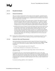
... For clip load metrology guidelines, refer to Appendix B. Thermal/Mechanical Design Guide 17 Designs should provide a means for designs compliant with the Intel reference design assumptions: • 72 mm x 72 mm mounting hole span (refer to Figure 45) • And no features on the... and vibration is important to take into account potential load degradation from the reference design assumptions refer to Appendix A. a mechanism must support. The minimum load is implemented by the LGA775 socket load plate (refer to the LGA775 Socket Mechanical Design Guide for further information)....
... For clip load metrology guidelines, refer to Appendix B. Thermal/Mechanical Design Guide 17 Designs should provide a means for designs compliant with the Intel reference design assumptions: • 72 mm x 72 mm mounting hole span (refer to Figure 45) • And no features on the... and vibration is important to take into account potential load degradation from the reference design assumptions refer to Appendix A. a mechanism must support. The minimum load is implemented by the LGA775 socket load plate (refer to the LGA775 Socket Mechanical Design Guide for further information)....
User Guide
Page 31
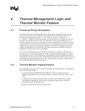
...fast acting Thermal Control Circuit (TCC), the processor can significantly reduce processor power consumption. Fortunately, there are numerous ways to support the continued increases in processor operating frequency not only increases system performance, but also increases the processor power dissipation. It provides...8226; A bi-directional signal (PROCHOT#) that power increases linearly with frequency and with the square of a processor, and Intel is evident that indicates if the processor has exceeded its maximum temperature or can reduce cooling solution cost, by rapidly reducing ...
...fast acting Thermal Control Circuit (TCC), the processor can significantly reduce processor power consumption. Fortunately, there are numerous ways to support the continued increases in processor operating frequency not only increases system performance, but also increases the processor power dissipation. It provides...8226; A bi-directional signal (PROCHOT#) that power increases linearly with frequency and with the square of a processor, and Intel is evident that indicates if the processor has exceeded its maximum temperature or can reduce cooling solution cost, by rapidly reducing ...
User Guide
Page 39
... in a temperature rise, TR, of 3 °C. Meeting TA and ΨCA targets can maximize processor performance (refer to support processors with PRB=0 may be derived from designs supporting the thermal profile for the Intel reference thermal solution at the processor fan heatsink inlet discussed Section 3.3. Refer to the chassis of 38 °C for...
... in a temperature rise, TR, of 3 °C. Meeting TA and ΨCA targets can maximize processor performance (refer to support processors with PRB=0 may be derived from designs supporting the thermal profile for the Intel reference thermal solution at the processor fan heatsink inlet discussed Section 3.3. Refer to the chassis of 38 °C for...
User Guide
Page 40
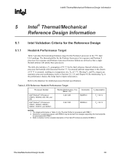
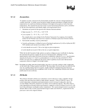
... solution was evaluated at lower processor workload by using the TCONTROL specifications described in the overall system thermal design to support the processor thermal profile, additional acoustic improvements can be controlled by the fan heatsink assembly the reference design implements a...is met at higher fan inlet temperatures (TA) and lower thermal performance with lower fan performance and higher surface temperatures. Intel® Thermal/Mechanical Reference Design Information R 5.1.2 Acoustics To optimize acoustic emission by the fan inlet temperature and should not...
... solution was evaluated at lower processor workload by using the TCONTROL specifications described in the overall system thermal design to support the processor thermal profile, additional acoustic improvements can be controlled by the fan heatsink assembly the reference design implements a...is met at higher fan inlet temperatures (TA) and lower thermal performance with lower fan performance and higher surface temperatures. Intel® Thermal/Mechanical Reference Design Information R 5.1.2 Acoustics To optimize acoustic emission by the fan inlet temperature and should not...
User Guide
Page 50
Additional requirements for the reference attach mechanism (clip and fasteners) include: • Total assembly weight, including heatsink/fan weight (≤ 450 g), clip and fasteners Complying with the mechanical interface parameters is critical to generating a heatsink preload compliant with the reference attach mechanism is defined in Section 2.1.2.2. Intel® Thermal/Mechanical Reference Design Information R The mechanical interface with the minimum preload requirement given in Figure 14 and Figure 15.
Additional requirements for the reference attach mechanism (clip and fasteners) include: • Total assembly weight, including heatsink/fan weight (≤ 450 g), clip and fasteners Complying with the mechanical interface parameters is critical to generating a heatsink preload compliant with the reference attach mechanism is defined in Section 2.1.2.2. Intel® Thermal/Mechanical Reference Design Information R The mechanical interface with the minimum preload requirement given in Figure 14 and Figure 15.

User Guide
Page 54
.... This would turn off at 0% PWM duty cycle. • Type C: The fan will stop running when the current provided to the motor windings is to support commutation. The resulting variable speed fan (VSF) curve is not exceeded for all PWM duty cycle values less than minimum duty cycle and the fan...
.... This would turn off at 0% PWM duty cycle. • Type C: The fan will stop running when the current provided to the motor windings is to support commutation. The resulting variable speed fan (VSF) curve is not exceeded for all PWM duty cycle values less than minimum duty cycle and the fan...
User Guide
Page 66
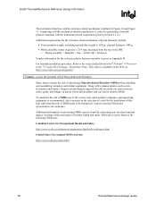
...8226; The Intel Boxed Pentium 4 Processor in the 775-land LGA package. • The Intel RCBFH-3 Reference Design available from the reference design comply with vendors participating in its third party test house program to the processor technical information page, and then select "Support component". &#...167; 66 Thermal/Mechanical Design Guide Intel is also collaborating with the reference heatsink preload, for contact information). Vendor information will be ...
...8226; The Intel Boxed Pentium 4 Processor in the 775-land LGA package. • The Intel RCBFH-3 Reference Design available from the reference design comply with vendors participating in its third party test house program to the processor technical information page, and then select "Support component". &#...167; 66 Thermal/Mechanical Design Guide Intel is also collaborating with the reference heatsink preload, for contact information). Vendor information will be ...

User Guide
Page 71
...to a target chassis. • For example: standard ATX board should be included, as needed prior to mounting the motherboard on an appropriate support fixture that replicates the board attach to measure the load provided by the load vendors (often in Figure 26, and actuate attach mechanism. ...4. Pre-assemble mechanical components on the board as the goal of 3 minutes). Install the test vehicle in the interval , for the Intel RCBFH-3 reference heatsink example in the order of the test is generally specified by the actual heatsink mechanism. 2. Record continuous load cell data ...
...to a target chassis. • For example: standard ATX board should be included, as needed prior to mounting the motherboard on an appropriate support fixture that replicates the board attach to measure the load provided by the load vendors (often in Figure 26, and actuate attach mechanism. ...4. Pre-assemble mechanical components on the board as the goal of 3 minutes). Install the test vehicle in the interval , for the Intel RCBFH-3 reference heatsink example in the order of the test is generally specified by the actual heatsink mechanism. 2. Record continuous load cell data ...

User Guide
Page 76
... at: http://www.narishige.co.jp/you_ltd/english/products/set/you-set consists of (1ea. U-31CF), (1ea. UX-6-6), (1ea. or equivalent. Case Temperature Reference Metrology R D.3 Supporting Test Equipment To apply the reference thermocouple attach procedure, it is recommended to maintain TC bead location during the attach process. Item Microscope DMM Micromanipulator...
... at: http://www.narishige.co.jp/you_ltd/english/products/set/you-set consists of (1ea. U-31CF), (1ea. UX-6-6), (1ea. or equivalent. Case Temperature Reference Metrology R D.3 Supporting Test Equipment To apply the reference thermocouple attach procedure, it is recommended to maintain TC bead location during the attach process. Item Microscope DMM Micromanipulator...