Data Sheet
Page 3
... 14 2.4 Reserved, Unused, and TESTHI Signals 16 2.5 Power Segment Identifier (PSID 16 2.6 Voltage and Current Specification 17 2.6.1 Absolute Maximum and Minimum Ratings 17 2.6.2 DC Voltage and Current Specification 18 2.6.3 VCC Overshoot 23 2.6.4 Die Voltage Validation 24 2.7 Signaling Specifications 24 2.7.1 FSB Signal Groups 25 2.7.2 CMOS and Open Drain Signals 26 2.7.3 Processor DC Specifications 27...
... 14 2.4 Reserved, Unused, and TESTHI Signals 16 2.5 Power Segment Identifier (PSID 16 2.6 Voltage and Current Specification 17 2.6.1 Absolute Maximum and Minimum Ratings 17 2.6.2 DC Voltage and Current Specification 18 2.6.3 VCC Overshoot 23 2.6.4 Die Voltage Validation 24 2.7 Signaling Specifications 24 2.7.1 FSB Signal Groups 25 2.7.2 CMOS and Open Drain Signals 26 2.7.3 Processor DC Specifications 27...

Data Sheet
Page 5
Left Side 44 13 land-out Diagram (Top View - Figures 1 2 Intel® Intel® Core™2 Core™2 Duo Duo Processor Processor E8000 E7000 Series Series VCC VCC Static Static and and Transient Transient Tolerance Tolerance 21 23 3 VCC ...Points 99 Datasheet 5 Right Side 45 14 Intel® Core™2 Duo Processor E8000 Series Thermal Profile 79 15 Intel® Core™2 Duo Processor E7000 Series Thermal Profile 80 16 Case Temperature (TC) Measurement Location 81 17 Thermal Monitor 2 Frequency and Voltage Ordering 83 18 Conceptual Fan Control Diagram ...
Left Side 44 13 land-out Diagram (Top View - Figures 1 2 Intel® Intel® Core™2 Core™2 Duo Duo Processor Processor E8000 E7000 Series Series VCC VCC Static Static and and Transient Transient Tolerance Tolerance 21 23 3 VCC ...Points 99 Datasheet 5 Right Side 45 14 Intel® Core™2 Duo Processor E8000 Series Thermal Profile 79 15 Intel® Core™2 Duo Processor E7000 Series Thermal Profile 80 16 Case Temperature (TC) Measurement Location 81 17 Thermal Monitor 2 Frequency and Voltage Ordering 83 18 Conceptual Fan Control Diagram ...
Data Sheet
Page 6
... Maximum and Minimum Ratings 17 4 Voltage and Current Specifications 18 5 6 Intel® Intel® Core™2 Core™2 Duo Duo Processor Processor E8000 E7000 Series Series VCC VCC Static Static and and Transient Transient Tolerance Tolerance 20 22 7 VCC Overshoot Specifications 23 8 FSB Signal Groups ...25 9 Signal Characteristics 26 10 Signal Reference Voltages 26 11 GTL+ Signal Group...
... Maximum and Minimum Ratings 17 4 Voltage and Current Specifications 18 5 6 Intel® Intel® Core™2 Core™2 Duo Duo Processor Processor E8000 E7000 Series Series VCC VCC Static Static and and Transient Transient Tolerance Tolerance 20 22 7 VCC Overshoot Specifications 23 8 FSB Signal Groups ...25 9 Signal Characteristics 26 10 Signal Reference Voltages 26 11 GTL+ Signal Group...
Data Sheet
Page 8
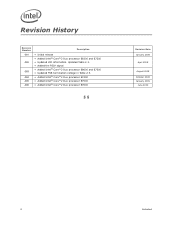
... VID information. Updated Table 2-1. • Added the PSI# signal • Added Intel® Core™2 Duo processor E8600 and E7300 • Updated FSB termination voltage in Table 2-3. • Added Intel® Core™2 Duo processor E7400 • Added Intel® Core™2 Duo processor E7500 • Added Intel® Core™2 Duo processor E7600 § § Revision Date January 2008 April 2008 August...
... VID information. Updated Table 2-1. • Added the PSI# signal • Added Intel® Core™2 Duo processor E8600 and E7300 • Updated FSB termination voltage in Table 2-3. • Added Intel® Core™2 Duo processor E7400 • Added Intel® Core™2 Duo processor E7500 • Added Intel® Core™2 Duo processor E7600 § § Revision Date January 2008 April 2008 August...

Data Sheet
Page 10
.... • Integrated heat spreader (IHS) -A component of the Intel® Core™2 Duo processor E8000 series and Intel® Core™2 Duo processor E7000 series. • Voltage Regulator Design Guide - Since the LGA775 socket does not include any mechanical features for Intel® architecture-based desktop, mobile and mainstream server multi-core processors. Component thermal solutions should attach to the...
.... • Integrated heat spreader (IHS) -A component of the Intel® Core™2 Duo processor E8000 series and Intel® Core™2 Duo processor E7000 series. • Voltage Regulator Design Guide - Since the LGA775 socket does not include any mechanical features for Intel® architecture-based desktop, mobile and mainstream server multi-core processors. Component thermal solutions should attach to the...

Data Sheet
Page 11
...a set of viruses or worms that exploit buffer over run in a tray, or loose. See the Intel® Architecture Software Developer's Manual for widely-deployed virtualization solutions and enables more detailed information. • Intel® 64 Architecture- Further details on the client PC. • Platform... in non-executable memory the processor raises an error to any supply voltages, have any I/Os biased, or receive any clocks. Processors may lower average power consumption (in accordance with an Intel TXT enabled OS to run vulnerabilities and can be found at http://...
...a set of viruses or worms that exploit buffer over run in a tray, or loose. See the Intel® Architecture Software Developer's Manual for widely-deployed virtualization solutions and enables more detailed information. • Intel® 64 Architecture- Further details on the client PC. • Platform... in non-executable memory the processor raises an error to any supply voltages, have any I/Os biased, or receive any clocks. Processors may lower average power consumption (in accordance with an Intel TXT enabled OS to run vulnerabilities and can be found at http://...

Data Sheet
Page 12
References Document Location Intel® Core™2 Duo Processor E8000 and E7000 Series Specification Update Intel® Core™2 Duo Processor E8000 and E7000 Series and Intel® Pentium Dual-Core Processor E6000 and E5000 Series Thermal and Mechanical Design Guidelines Voltage Regulator-Down (VRD) 11.0 Processor Power Delivery Design Guidelines For Desktop LGA775 Socket LGA775 Socket Mechanical Design Guide Intel® 64...
References Document Location Intel® Core™2 Duo Processor E8000 and E7000 Series Specification Update Intel® Core™2 Duo Processor E8000 and E7000 Series and Intel® Pentium Dual-Core Processor E6000 and E5000 Series Thermal and Mechanical Design Guidelines Voltage Regulator-Down (VRD) 11.0 Processor Power Delivery Design Guidelines For Desktop LGA775 Socket LGA775 Socket Mechanical Design Guide Intel® 64...
Data Sheet
Page 13
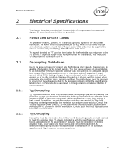
...by the front side bus and processor activity. The motherboard must be provided on the motherboard. Contact your Intel field representative for further information. Power and Ground Lands The processor has VCC (power), VTT, and VSS (ground... Table 4. In addition, ceramic decoupling capacitors are provided. This may cause voltages on -chip power distribution. Consult the Voltage Regulator-Down (VRD) 11.0 Processor Power Delivery Design Guidelines For Desktop LGA775 Socket for additional information. Electrical Specifications 2 Electrical Specifications 2.1 2.2 2.2.1 2.2.2...
...by the front side bus and processor activity. The motherboard must be provided on the motherboard. Contact your Intel field representative for further information. Power and Ground Lands The processor has VCC (power), VTT, and VSS (ground... Table 4. In addition, ceramic decoupling capacitors are provided. This may cause voltages on -chip power distribution. Consult the Voltage Regulator-Down (VRD) 11.0 Processor Power Delivery Design Guidelines For Desktop LGA775 Socket for additional information. Electrical Specifications 2 Electrical Specifications 2.1 2.2 2.2.1 2.2.2...

Data Sheet
Page 14
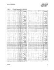
...by the Voltage Regulator-Down (VRD) 11.0 Processor Power Delivery Design Guidelines For Desktop LGA775 Socket. Voltage Identification The Voltage Identification (VID) specification for each processor frequency is defined by the motherboard for VCC overshoot specifications). A '1' in Table 4. Voltages for the... across the VCC_SENSE and VSS_SENSE lands. In addition, some of regulating its associated processor core voltage (VCC). Refer to the Intel® Core™2 Duo Processor E8000 and E7000 Series Specification Update for these signals. This is reflected by the...
...by the Voltage Regulator-Down (VRD) 11.0 Processor Power Delivery Design Guidelines For Desktop LGA775 Socket. Voltage Identification The Voltage Identification (VID) specification for each processor frequency is defined by the motherboard for VCC overshoot specifications). A '1' in Table 4. Voltages for the... across the VCC_SENSE and VSS_SENSE lands. In addition, some of regulating its associated processor core voltage (VCC). Refer to the Intel® Core™2 Duo Processor E8000 and E7000 Series Specification Update for these signals. This is reflected by the...
Data Sheet
Page 15
... 1.15 0 1 0 0 1 1 0 0 1.1375 0 1 0 0 1 1 1 0 1.125 0 1 0 1 0 0 0 0 1.1125 01010010 1.1 0 1 0 1 0 1 0 0 1.0875 0 1 0 1 0 1 1 0 1.075 0 1 0 1 1 0 0 0 1.0625 01011010 1.05 VID VID VID VID VID VID VID VID 76543210 Voltage 0 1 0 1 1 1 0 0 1.0375 0 1 0 1 1 1 1 0 1.025 0 1 1 0 0 0 0 0 1.0125 01100010 1 0 1 1 0 0 1 0 0 0.9875 0 1 1 0 0 1 1 0 0.975 0 1 1 0 1 0 0 0 0.9625 01101010 0.95 0 1 1 0 1 1 0 0 0.9375 0 1 1 0 1 1 1 0 0.925 0 1 1 1 0 0 0 0 0.9125 01110010 0.9 0 1 1 1 0 1 0 0 0.8875 0 1 1 1 0 1 1 0 0.875 0 1 1 1 1 0 0 0 0.8625 01111010 0.85 0 1 1 1 1 1 0 0 0.8375...
... 1.15 0 1 0 0 1 1 0 0 1.1375 0 1 0 0 1 1 1 0 1.125 0 1 0 1 0 0 0 0 1.1125 01010010 1.1 0 1 0 1 0 1 0 0 1.0875 0 1 0 1 0 1 1 0 1.075 0 1 0 1 1 0 0 0 1.0625 01011010 1.05 VID VID VID VID VID VID VID VID 76543210 Voltage 0 1 0 1 1 1 0 0 1.0375 0 1 0 1 1 1 1 0 1.025 0 1 1 0 0 0 0 0 1.0125 01100010 1 0 1 1 0 0 1 0 0 0.9875 0 1 1 0 0 1 1 0 0.975 0 1 1 0 1 0 0 0 0.9625 01101010 0.95 0 1 1 0 1 1 0 0 0.9375 0 1 1 0 1 1 1 0 0.925 0 1 1 1 0 0 0 0 0.9125 01110010 0.9 0 1 1 1 0 1 0 0 0.8875 0 1 1 1 0 1 1 0 0.875 0 1 1 1 1 0 0 0 0.8625 01111010 0.85 0 1 1 1 1 1 0 0 0.8375...
Data Sheet
Page 16
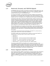
... Boundary Scan testing of these lands to VCC, VSS, VTT, or to power or ground. Unused outputs may use requires more power than the platform voltage regulator (VR) is provided on -die termination resistors (RTT). See Chapter 4 for each other TESTHI signals • TESTHI9/FC43 - Unused outputs can result in component...
... Boundary Scan testing of these lands to VCC, VSS, VTT, or to power or ground. Unused outputs may use requires more power than the platform voltage regulator (VR) is provided on -die termination resistors (RTT). See Chapter 4 for each other TESTHI signals • TESTHI9/FC43 - Unused outputs can result in component...
Data Sheet
Page 17
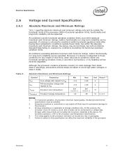
... can be expected. Absolute Maximum and Minimum Ratings Symbol Parameter Min VCC VTT TCASE TSTORAGE Core voltage with respect to VSS FSB termination voltage with its reliability will likely result in permanent damage to these conditions for any tray or packaging. 5. Storage temperature is subjected to the processor. 3. Datasheet 17 Although the processor contains...
... can be expected. Absolute Maximum and Minimum Ratings Symbol Parameter Min VCC VTT TCASE TSTORAGE Core voltage with respect to VSS FSB termination voltage with its reliability will likely result in permanent damage to these conditions for any tray or packaging. 5. Storage temperature is subjected to the processor. 3. Datasheet 17 Although the processor contains...

Data Sheet
Page 18
Electrical Specifications 2.6.2 DC Voltage and Current Specification Table 4. Voltage and Current Specifications Symbol Parameter Min Typ Max Unit Notes2, 10 VID Range VID 0.8500 - 1.3625 V 1 Core VCC Processor Number (6 MB Cache): E8600 E8500 E8400 E8300 E8200 E8190 Processor Number (3 ... 75 75 - 75 75 75 75 75 - 75 75 75 75 V V A6 A FSB termination voltage on Intel 3 series Chipset family boards 1.045 1.1 1.155 VTT (DC + AC specifications) on Intel 4 series Chipset family boards 1.14 V 7, 8 1.2 1.26 VTT_OUT_LEFT and VTT_OUT_RIGHT ICC DC Current that may...
Electrical Specifications 2.6.2 DC Voltage and Current Specification Table 4. Voltage and Current Specifications Symbol Parameter Min Typ Max Unit Notes2, 10 VID Range VID 0.8500 - 1.3625 V 1 Core VCC Processor Number (6 MB Cache): E8600 E8500 E8400 E8300 E8200 E8190 Processor Number (3 ... 75 75 - 75 75 75 75 75 - 75 75 75 75 V V A6 A FSB termination voltage on Intel 3 series Chipset family boards 1.045 1.1 1.155 VTT (DC + AC specifications) on Intel 4 series Chipset family boards 1.14 V 7, 8 1.2 1.26 VTT_OUT_LEFT and VTT_OUT_RIGHT ICC DC Current that may...

Data Sheet
Page 19
... ICC for more information. 4. Individual maximum VID values are based on -board termination (RTT), through the signal line. A variable voltage source should be updated with a 100 MHz bandwidth oscilloscope, 1.5 pF maximum probe capacitance, and 1 MΩ minimum impedance. This ... drawn by the processor during manufacturing such that this table are calibrated during a power management event (Thermal Monitor 2, Enhanced Intel SpeedStep® technology, or Extended HALT State). 2. Electrical Specifications Table 4. Note that two processors at the socket with ...
... ICC for more information. 4. Individual maximum VID values are based on -board termination (RTT), through the signal line. A variable voltage source should be updated with a 100 MHz bandwidth oscilloscope, 1.5 pF maximum probe capacitance, and 1 MΩ minimum impedance. This ... drawn by the processor during manufacturing such that this table are calibrated during a power management event (Thermal Monitor 2, Enhanced Intel SpeedStep® technology, or Extended HALT State). 2. Electrical Specifications Table 4. Note that two processors at the socket with ...

Data Sheet
Page 20
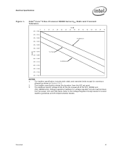
... 2.6.3. 2. Adherence to this loadline specification is intended to the Voltage Regulator Design Guide for voltage regulator circuits must be taken from VID Setting (V)1, 2, 3, 4 Maximum Voltage 1.40 mΩ Typical Voltage 1.48 mΩ Minimum Voltage 1.55 mΩ 0 0.000 5 -0.007 10 -0.014 ... -0.077 -0.085 -0.092 -0.100 -0.108 -0.116 -0.123 -0.131 -0.139 -0.147 -0.154 NOTES: 1. Intel® Core™2 Duo Processor E8000 Series VCC Static and Transient Tolerance ICC (A) Voltage Deviation from processor VCC and VSS lands. Electrical Specifications Table 5.
... 2.6.3. 2. Adherence to this loadline specification is intended to the Voltage Regulator Design Guide for voltage regulator circuits must be taken from VID Setting (V)1, 2, 3, 4 Maximum Voltage 1.40 mΩ Typical Voltage 1.48 mΩ Minimum Voltage 1.55 mΩ 0 0.000 5 -0.007 10 -0.014 ... -0.077 -0.085 -0.092 -0.100 -0.108 -0.116 -0.123 -0.131 -0.139 -0.147 -0.154 NOTES: 1. Intel® Core™2 Duo Processor E8000 Series VCC Static and Transient Tolerance ICC (A) Voltage Deviation from processor VCC and VSS lands. Electrical Specifications Table 5.
Data Sheet
Page 21
...VID set point. 3. Refer to the Voltage Regulator Design Guide for overshoot allowed as shown in Section 2.6.3. 2. The loadline specification includes both static and transient limits except for socket loadline guidelines and VR implementation details. Datasheet 21 Intel® Core™2 Duo Processor E8000 Series VCC Static and Transient ... 20 25 30 35 40 45 50 55 60 65 70 75 Vcc Maximum Vcc Typical Vcc Minimum NOTES: 1. The loadlines specify voltage limits at the die measured at the VCC_SENSE and VSS_SENSE lands. Electrical Specifications Figure 1.
...VID set point. 3. Refer to the Voltage Regulator Design Guide for overshoot allowed as shown in Section 2.6.3. 2. The loadline specification includes both static and transient limits except for socket loadline guidelines and VR implementation details. Datasheet 21 Intel® Core™2 Duo Processor E8000 Series VCC Static and Transient ... 20 25 30 35 40 45 50 55 60 65 70 75 Vcc Maximum Vcc Typical Vcc Minimum NOTES: 1. The loadlines specify voltage limits at the die measured at the VCC_SENSE and VSS_SENSE lands. Electrical Specifications Figure 1.

Data Sheet
Page 22
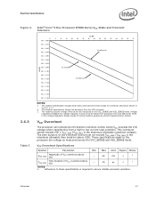
... at the die measured at the VCC_SENSE and VSS_SENSE lands. Refer to ensure reliable processor operation. 22 Datasheet Intel® Core™2 Duo Processor E7000 Series VCC Static and Transient Tolerance ICC (A) Voltage Deviation from processor VCC and VSS lands. Adherence to this loadline specification is intended to aid in Section 2.6.3. 2. The loadline specification...
... at the die measured at the VCC_SENSE and VSS_SENSE lands. Refer to ensure reliable processor operation. 22 Datasheet Intel® Core™2 Duo Processor E7000 Series VCC Static and Transient Tolerance ICC (A) Voltage Deviation from processor VCC and VSS lands. Adherence to this loadline specification is intended to aid in Section 2.6.3. 2. The loadline specification...
Data Sheet
Page 23
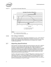
... of VCC overshoot above VID - 50 mV 3 1 TOS_MAX Time duration of the overshoot event must be taken from processor VCC and VSS lands. Intel® Core™2 Duo Processor E7000 Series VCC Static and Transient Tolerance Vcc [V] 0 VID - 0.000 VID - 0.013 VID - 0.025 VID - 0.038 VID ...duration above VID - 25 µs 3 1 NOTES: 1. This loadline specification shows the deviation from a high to the processor die voltage as shown in Section 2.6.3. 2. The time duration of VCC overshoot above VID). These specifications apply to low current load condition. The ...
... of VCC overshoot above VID - 50 mV 3 1 TOS_MAX Time duration of the overshoot event must be taken from processor VCC and VSS lands. Intel® Core™2 Duo Processor E7000 Series VCC Static and Transient Tolerance Vcc [V] 0 VID - 0.000 VID - 0.013 VID - 0.025 VID - 0.038 VID ...duration above VID - 25 µs 3 1 NOTES: 1. This loadline specification shows the deviation from a high to the processor die voltage as shown in Section 2.6.3. 2. The time duration of VCC overshoot above VID). These specifications apply to low current load condition. The ...
Data Sheet
Page 24
...processor frequency increases. GTLREF must be generated on processor must meet the specifications in duration may be ignored. The GTL+ inputs require a reference voltage (GTLREF) which is used by the receivers to 100 MHz bandwidth limit. Termination resistors (RTT) for GTL+ signals are provided on the ...processor silicon and are terminated to terminate the bus on -die termination, thus eliminating the need to VTT. Intel chipsets will also provide on the motherboard for each processor (and chipset), separate VCC and VTT supplies are < 10 ns in Table 7 ...
...processor frequency increases. GTLREF must be generated on processor must meet the specifications in duration may be ignored. The GTL+ inputs require a reference voltage (GTLREF) which is used by the receivers to 100 MHz bandwidth limit. Termination resistors (RTT) for GTL+ signals are provided on the ...processor silicon and are terminated to terminate the bus on -die termination, thus eliminating the need to VTT. Intel chipsets will also provide on the motherboard for each processor (and chipset), separate VCC and VTT supplies are < 10 ns in Table 7 ...
Data Sheet
Page 26
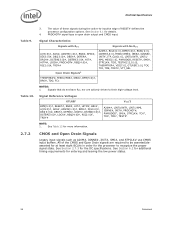
...#, IERR#, BPM[5:0]#, BR0#, TDO, FCx NOTES: 1. All of the CMOS and Open Drain signals are actively driven to their high-voltage level. See Section 2.7.3 for details. 4. Table 9. Table 10. 3. Signal Reference Voltages GTLREF BPM[5:0]#, RESET#, BNR#, HIT#, HITM#, BR0#, A[35:0]#, ADS#, ADSTB[1:0]#, BPRI#, D[63:0]#, DBI[3:0]#, DBSY#, DEFER#, DRDY#, DSTBN[3:0]#, DSTBP[3:0]#, LOCK#, REQ...
...#, IERR#, BPM[5:0]#, BR0#, TDO, FCx NOTES: 1. All of the CMOS and Open Drain signals are actively driven to their high-voltage level. See Section 2.7.3 for details. 4. Table 9. Table 10. 3. Signal Reference Voltages GTLREF BPM[5:0]#, RESET#, BNR#, HIT#, HITM#, BR0#, A[35:0]#, ADS#, ADSTB[1:0]#, BPRI#, D[63:0]#, DBI[3:0]#, DBSY#, DEFER#, DRDY#, DSTBN[3:0]#, DSTBP[3:0]#, LOCK#, REQ...