
Product Guide
Page 5
...; Z68 Express Chipset 16 Intel® Rapid Storage Technology 16 Intel® Smart Response Technology 16 Audio Subsystem 16 LAN Subsystem 17 USB Support ...18 SATA Support...18 SATA RAID 19 Legacy I/O ...19 Expandability...19 Bluetooth*/WiFi Support 20 Bluetooth Technology 20 WiFi 802.11 Wireless 20 BIOS ...21 Serial ATA Auto Configuration... PME# Signal Wake-up Support 26 WAKE# Signal Wake-up Support 26 Wake from Consumer IR 27 Wake from Serial Port 27 Onboard Power and Reset Buttons 27 Board Status LEDs 28 Speaker...30 Battery ...30 Real-Time Clock 30 v
...; Z68 Express Chipset 16 Intel® Rapid Storage Technology 16 Intel® Smart Response Technology 16 Audio Subsystem 16 LAN Subsystem 17 USB Support ...18 SATA Support...18 SATA RAID 19 Legacy I/O ...19 Expandability...19 Bluetooth*/WiFi Support 20 Bluetooth Technology 20 WiFi 802.11 Wireless 20 BIOS ...21 Serial ATA Auto Configuration... PME# Signal Wake-up Support 26 WAKE# Signal Wake-up Support 26 Wake from Consumer IR 27 Wake from Serial Port 27 Onboard Power and Reset Buttons 27 Board Status LEDs 28 Speaker...30 Battery ...30 Real-Time Clock 30 v
Product Guide
Page 7
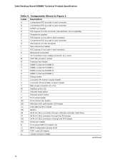
...of the Diagnostic LEDs 29 7. Lift the Processor Socket Load Plate 36 11. Connecting the Processor Fan Heat Sink Power Cable to BIOS Button 22 4. Example Dual Channel Memory Configuration with Four DIMMs 41 17. Installing Linked PCI Express Graphics Cards 47 23. Location ...the Processor Socket Load Plate in Place 38 14. Installing a PCI Express x16 Graphics Card 45 21. Intel Desktop Board DZ68BC Components 12 2. Use DDR3 DIMMs 42 19. Onboard Power and Reset Buttons 27 6. Connecting SATA Cables 48 24. Internal Headers and Connectors 49 vii Installing the I/O Shield ...
...of the Diagnostic LEDs 29 7. Lift the Processor Socket Load Plate 36 11. Connecting the Processor Fan Heat Sink Power Cable to BIOS Button 22 4. Example Dual Channel Memory Configuration with Four DIMMs 41 17. Installing Linked PCI Express Graphics Cards 47 23. Location ...the Processor Socket Load Plate in Place 38 14. Installing a PCI Express x16 Graphics Card 45 21. Intel Desktop Board DZ68BC Components 12 2. Use DDR3 DIMMs 42 19. Onboard Power and Reset Buttons 27 6. Connecting SATA Cables 48 24. Internal Headers and Connectors 49 vii Installing the I/O Shield ...

Product Guide
Page 13
Desktop Board Features Table 2. Intel Desktop Board DZ68BC Components Label Description A PCI bus connector B PCI bus connector C ... pin) V Standby power indicator LED W Onboard reset button X Onboard power button Y Front panel header Z Front chassis fan header AA Alternate front panel power LED header BB Intel Z68 PCH CC Battery DD Two 6.0 Gb/s SATA... ports (Marvell controller) EE Two 6.0 Gb/s SATA ports (Intel Z68 PCH) FF Four 3.0 Gb/s SATA ports (Intel Z68 PCH) GG Serial port header HH USB 2.0 headers II BIOS...
Desktop Board Features Table 2. Intel Desktop Board DZ68BC Components Label Description A PCI bus connector B PCI bus connector C ... pin) V Standby power indicator LED W Onboard reset button X Onboard power button Y Front panel header Z Front chassis fan header AA Alternate front panel power LED header BB Intel Z68 PCH CC Battery DD Two 6.0 Gb/s SATA... ports (Marvell controller) EE Two 6.0 Gb/s SATA ports (Intel Z68 PCH) FF Four 3.0 Gb/s SATA ports (Intel Z68 PCH) GG Serial port header HH USB 2.0 headers II BIOS...
Product Guide
Page 21
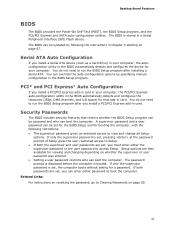
.... You do not need to boot the computer. If only the supervisor password is set , you must enter either password to run the BIOS Setup program after installing a Serial ATA. If only the supervisor password is set, pressing at the password prompt of Setup gives the user...Chapter 3 starting on page 67. Related Links: For instructions on resetting the password, go to Setup. • If both passwords are then available for a password. Desktop Board Features BIOS The BIOS provides the Power-On Self-Test (POST), the BIOS Setup program, and the PCI/PCI Express and SATA auto-configuration...
.... You do not need to boot the computer. If only the supervisor password is set , you must enter either password to run the BIOS Setup program after installing a Serial ATA. If only the supervisor password is set, pressing at the password prompt of Setup gives the user...Chapter 3 starting on page 67. Related Links: For instructions on resetting the password, go to Setup. • If both passwords are then available for a password. Desktop Board Features BIOS The BIOS provides the Power-On Self-Test (POST), the BIOS Setup program, and the PCI/PCI Express and SATA auto-configuration...
Product Guide
Page 28
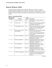
... voltage regulator temperature, and certain error conditions. Then the LED will stay on when memory initialization is complete. Intel Desktop Board DZ68BC Product Guide Board Status LEDs The Desktop Board includes thirteen LEDs that could affect performance. Then the LED will...flash when the video initialization activity starts. When the watch dog timer fires to reset the board, this LED indicates an elevated temperature on the processor that allow you to BIOS E Processor Initialization F Memory Initialization G Video Initialization H USB Initialization I Hard Drive...
... voltage regulator temperature, and certain error conditions. Then the LED will stay on when memory initialization is complete. Intel Desktop Board DZ68BC Product Guide Board Status LEDs The Desktop Board includes thirteen LEDs that could affect performance. Then the LED will...flash when the video initialization activity starts. When the watch dog timer fires to reset the board, this LED indicates an elevated temperature on the processor that allow you to BIOS E Processor Initialization F Memory Initialization G Video Initialization H USB Initialization I Hard Drive...
Product Guide
Page 75
... phase begin to end CPU DXE SMM phase begin to end 50-52 58, 59 5A, 5B 5F I/O Buses PCI enumeration, allocation, hot plug Resetting USB bus Resetting SATA bus and all devices Unrecoverable error, start with PIC 60-6F E4 E7 E8 E9 EB Boot Device Selection (BDS) BDS driver entry... Entered DXE phase Waiting for user input Checking password Entering BIOS setup Calling legacy option ROMs 90-95 98-9B Keyboard/Mouse (PS/2 or USB) Keyboard...
... phase begin to end CPU DXE SMM phase begin to end 50-52 58, 59 5A, 5B 5F I/O Buses PCI enumeration, allocation, hot plug Resetting USB bus Resetting SATA bus and all devices Unrecoverable error, start with PIC 60-6F E4 E7 E8 E9 EB Boot Device Selection (BDS) BDS driver entry... Entered DXE phase Waiting for user input Checking password Entering BIOS setup Calling legacy option ROMs 90-95 98-9B Keyboard/Mouse (PS/2 or USB) Keyboard...
Technical Product Specification
Page 8
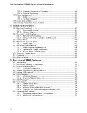
Intel Desktop Board DZ68BC Technical Product Specification 1.13.3 Chassis Intrusion and Detection 34 1.13.4 Thermal Monitoring 35 1.14 Power Management 36 1.14.1 ACPI 36 1.14.2 Hardware Support 39 1.15 Board Status LEDs 43 1.16 Onboard Power and Reset Buttons 45... 68 3 Overview of BIOS Features 3.1 Introduction 69 3.2 BIOS Flash Memory Organization 70 3.3 Resource Configuration 70 3.3.1 PCI Autoconfiguration 70 3.4 System Management BIOS (SMBIOS 71 3.5 Legacy USB Support 71 3.6 BIOS Updates 72 3.6.1 Language Support 72 3.6.2 Custom Splash Screen 73 3.7 BIOS Recovery 73 3.8 Boot...
Intel Desktop Board DZ68BC Technical Product Specification 1.13.3 Chassis Intrusion and Detection 34 1.13.4 Thermal Monitoring 35 1.14 Power Management 36 1.14.1 ACPI 36 1.14.2 Hardware Support 39 1.15 Board Status LEDs 43 1.16 Onboard Power and Reset Buttons 45... 68 3 Overview of BIOS Features 3.1 Introduction 69 3.2 BIOS Flash Memory Organization 70 3.3 Resource Configuration 70 3.3.1 PCI Autoconfiguration 70 3.4 System Management BIOS (SMBIOS 71 3.5 Legacy USB Support 71 3.6 BIOS Updates 72 3.6.1 Language Support 72 3.6.2 Custom Splash Screen 73 3.7 BIOS Recovery 73 3.8 Boot...
Technical Product Specification
Page 9
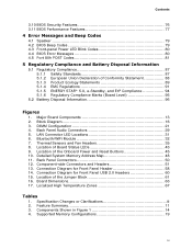
... 60 15. Board Dimensions 63 17. Contents 3.10 BIOS Security Features 76 3.11 BIOS Performance Features 77 4 Error Messages and Beep Codes 4.1 Speaker 79 4.2 BIOS Beep Codes 79 4.3 Front-panel Power LED Blink Codes 80 4.4 BIOS Error Messages 80 4.5 Port 80h POST Codes 81 5... Regulatory Compliance and Battery Disposal Information 5.1 Regulatory Compliance 87 5.1.1 Safety Standards 87 5.1.2 European Union Declaration of the Onboard Power and Reset Buttons 45 10. Thermal Sensors and Fan...
... 60 15. Board Dimensions 63 17. Contents 3.10 BIOS Security Features 76 3.11 BIOS Performance Features 77 4 Error Messages and Beep Codes 4.1 Speaker 79 4.2 BIOS Beep Codes 79 4.3 Front-panel Power LED Blink Codes 80 4.4 BIOS Error Messages 80 4.5 Port 80h POST Codes 81 5... Regulatory Compliance and Battery Disposal Information 5.1 Regulatory Compliance 87 5.1.1 Safety Standards 87 5.1.2 European Union Declaration of the Onboard Power and Reset Buttons 45 10. Thermal Sensors and Fan...
Technical Product Specification
Page 14
Intel Desktop Board DZ68BC Technical Product Specification Table 3. x16 ...x 12) W Standby power LED X Onboard reset button Y Onboard power button Z Front panel header AA Front chassis fan header BB Alternate front panel power LED header CC Intel Z68 Express Chipset DD Battery EE SATA 6.0 Gb.../s connector through a Marvell controller (light blue) FF SATA 6.0 Gb/s connector through the PCH (blue) GG SATA 3.0 Gb/s connectors through the PCH (black) HH Serial port header II Front panel USB 2.0 headers (4) JJ BIOS...
Intel Desktop Board DZ68BC Technical Product Specification Table 3. x16 ...x 12) W Standby power LED X Onboard reset button Y Onboard power button Z Front panel header AA Front chassis fan header BB Alternate front panel power LED header CC Intel Z68 Express Chipset DD Battery EE SATA 6.0 Gb.../s connector through a Marvell controller (light blue) FF SATA 6.0 Gb/s connector through the PCH (blue) GG SATA 3.0 Gb/s connectors through the PCH (black) HH Serial port header II Front panel USB 2.0 headers (4) JJ BIOS...
Technical Product Specification
Page 27
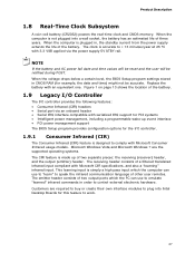
... operating systems. The CIR feature is made up event interface • PCI power management support The BIOS Setup program provides configuration options for the I /O controller provides the following features: • Consumer ...The I /O controller. 1.9.1 Consumer Infrared (CIR) The Consumer Infrared (CIR) feature is not plugged into Intel Desktop Boards for example, the date and time) might not be notified during POST. NOTE If the ...battery and AC power fail date and time values will be reset and the user will be accurate. Figure 1 on page 13 shows the location of ...
... operating systems. The CIR feature is made up event interface • PCI power management support The BIOS Setup program provides configuration options for the I /O controller provides the following features: • Consumer ...The I /O controller. 1.9.1 Consumer Infrared (CIR) The Consumer Infrared (CIR) feature is not plugged into Intel Desktop Boards for example, the date and time) might not be notified during POST. NOTE If the ...battery and AC power fail date and time values will be reset and the user will be accurate. Figure 1 on page 13 shows the location of ...
Technical Product Specification
Page 80
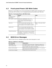
... and provides a brief description of 16 blinks. System did not find a device to reset values. Front-panel Power LED Blink Codes Type Pattern F2 Setup/F10 Boot Menu Prompt None BIOS update in a total of each. Table 43. Replace the battery soon. CMOS memory ...each ) three times, then 2.5-second pause (off . Run Setup to boot. 80 Intel Desktop Board DZ68BC Technical Product Specification 4.3 Front-panel Power LED Blink Codes Whenever a recoverable error occurs during POST, the BIOS causes the board's front panel power LED to blink an error message describing the problem...
... and provides a brief description of 16 blinks. System did not find a device to reset values. Front-panel Power LED Blink Codes Type Pattern F2 Setup/F10 Boot Menu Prompt None BIOS update in a total of each. Table 43. Replace the battery soon. CMOS memory ...each ) three times, then 2.5-second pause (off . Run Setup to boot. 80 Intel Desktop Board DZ68BC Technical Product Specification 4.3 Front-panel Power LED Blink Codes Whenever a recoverable error occurs during POST, the BIOS causes the board's front panel power LED to blink an error message describing the problem...
Technical Product Specification
Page 85
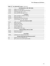
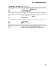
Port 80h POST Codes (continued) Port 80 Code Progress Code Enumeration Removable Media 0xB8 0xB9 0xBA Resetting removable media Disabling removable media Detecting presence of a removable media (IDE, CDROM detection etc.) 0xBB Enabling/configuring a removable media... DXE Core 0xE4 0xE7 Entered DXE phase Waiting for user input BDS 0xE8 Checking password 0xE9 Entering BIOS setup 0xEB Calling Legacy Option ROMs Runtime Phase/EFI OS Boot 0xF8 EFI boot service ExitBootServices ( ) has been called 0xF9 EFI runtime service...
Port 80h POST Codes (continued) Port 80 Code Progress Code Enumeration Removable Media 0xB8 0xB9 0xBA Resetting removable media Disabling removable media Detecting presence of a removable media (IDE, CDROM detection etc.) 0xBB Enabling/configuring a removable media... DXE Core 0xE4 0xE7 Entered DXE phase Waiting for user input BDS 0xE8 Checking password 0xE9 Entering BIOS setup 0xEB Calling Legacy Option ROMs Runtime Phase/EFI OS Boot 0xF8 EFI boot service ExitBootServices ( ) has been called 0xF9 EFI runtime service...
Technical Product Specification
Page 86
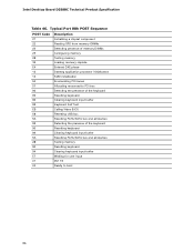
...Allocating resourced to PCI bus 92 Detecting the presence of the keyboard 90 Resetting keyboard 94 Clearing keyboard input buffer 95 Keyboard Self Test EB Calling Video BIOS 58 Resetting USB bus 5A Resetting PATA/SATA bus and all devices 92 Detecting the presence of the ...keyboard 90 Resetting keyboard 94 Clearing keyboard input buffer 5A Resetting PATA/SATA bus and all devices 28 Testing memory 90 Resetting keyboard 94 Clearing keyboard input buffer E7 Waiting for user input 01 INT 19 00 Ready to boot 86 Intel Desktop Board DZ68BC Technical Product ...
...Allocating resourced to PCI bus 92 Detecting the presence of the keyboard 90 Resetting keyboard 94 Clearing keyboard input buffer 95 Keyboard Self Test EB Calling Video BIOS 58 Resetting USB bus 5A Resetting PATA/SATA bus and all devices 92 Detecting the presence of the ...keyboard 90 Resetting keyboard 94 Clearing keyboard input buffer 5A Resetting PATA/SATA bus and all devices 28 Testing memory 90 Resetting keyboard 94 Clearing keyboard input buffer E7 Waiting for user input 01 INT 19 00 Ready to boot 86 Intel Desktop Board DZ68BC Technical Product ...


