
Product Guide
Page 5
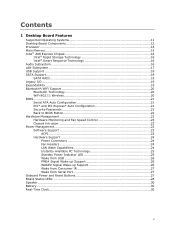
Contents 1 Desktop Board Features Supported Operating Systems 11 Desktop Board Components 12 Processor ...14 Main Memory...15 Intel® Z68 Express Chipset 16 Intel® Rapid Storage Technology 16 Intel® Smart Response Technology 16 Audio Subsystem 16 LAN Subsystem 17 USB Support ...18 SATA Support...18 SATA RAID 19 Legacy I/O ...19 Expandability...19 Bluetooth...
Contents 1 Desktop Board Features Supported Operating Systems 11 Desktop Board Components 12 Processor ...14 Main Memory...15 Intel® Z68 Express Chipset 16 Intel® Rapid Storage Technology 16 Intel® Smart Response Technology 16 Audio Subsystem 16 LAN Subsystem 17 USB Support ...18 SATA Support...18 SATA RAID 19 Legacy I/O ...19 Expandability...19 Bluetooth...
Product Guide
Page 6
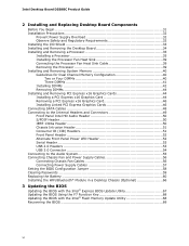
Intel Desktop Board DZ68BC Product Guide 2 Installing and Replacing Desktop Board Components Before You Begin 31 Installation Precautions 32 Prevent Power Supply Overload 32 Observe Safety and Regulatory Requirements 32 Installing the I/O Shield 33 Installing and Removing the Desktop Board 34 Installing and Removing a Processor 35 Installing a Processor 35 Installing the Processor... Fan Heat Sink 39 Connecting the Processor Fan Heat Sink Cable 39 Removing the Processor 39 Installing and Removing...
Intel Desktop Board DZ68BC Product Guide 2 Installing and Replacing Desktop Board Components Before You Begin 31 Installation Precautions 32 Prevent Power Supply Overload 32 Observe Safety and Regulatory Requirements 32 Installing the I/O Shield 33 Installing and Removing the Desktop Board 34 Installing and Removing a Processor 35 Installing a Processor 35 Installing the Processor... Fan Heat Sink 39 Connecting the Processor Fan Heat Sink Cable 39 Removing the Processor 39 Installing and Removing...
Product Guide
Page 7
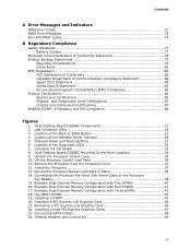
... Compliance 88 Figures 1. Location of the Diagnostic LEDs 29 7. Location of the Back to the Processor Fan Header 39 15. Intel Desktop Board DZ68BC Mounting Screw Hole Locations 34 9. Lift the Processor Socket Load Plate 36 11. Secure the Processor Socket Load Plate in Place 38 14. Example Dual Channel Memory Configuration with Four DIMMs...
... Compliance 88 Figures 1. Location of the Diagnostic LEDs 29 7. Location of the Back to the Processor Fan Header 39 15. Intel Desktop Board DZ68BC Mounting Screw Hole Locations 34 9. Lift the Processor Socket Load Plate 36 11. Secure the Processor Socket Load Plate in Place 38 14. Example Dual Channel Memory Configuration with Four DIMMs...
Product Guide
Page 9
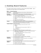
... an onboard header • Thermal and hardware management continued 9 Table 1 summarizes the major features of Intel® Desktop Board DZ68BC. 1 Desktop Board Features This chapter briefly describes the features of the Desktop Board. Feature Summary Form Factor Processor Main Memory Chipset ATX (304.80 millimeters [12.00 inches] x 243.84 millimeters [9.60 inches...
... an onboard header • Thermal and hardware management continued 9 Table 1 summarizes the major features of Intel® Desktop Board DZ68BC. 1 Desktop Board Features This chapter briefly describes the features of the Desktop Board. Feature Summary Form Factor Processor Main Memory Chipset ATX (304.80 millimeters [12.00 inches] x 243.84 millimeters [9.60 inches...

Product Guide
Page 13
...H PCI Express 2.0 x16 connector I Rear chassis fan header J PCI Express 2.0 x1 connector K Back panel connectors L 12 V processor core voltage connector (2 x 4 pin) M Processor socket N Processor fan header O DIMM 3 socket P DIMM 1 socket Q DIMM 4 socket R DIMM 2 socket S Front panel CIR receiver (...Intel Z68 PCH) FF Four 3.0 Gb/s SATA ports (Intel Z68 PCH) GG Serial port header HH USB 2.0 headers II BIOS configuration jumper block JJ POST code LED display KK Chassis intrusion header continued 13 Desktop Board Features Table 2. Intel Desktop Board DZ68BC...
...H PCI Express 2.0 x16 connector I Rear chassis fan header J PCI Express 2.0 x1 connector K Back panel connectors L 12 V processor core voltage connector (2 x 4 pin) M Processor socket N Processor fan header O DIMM 3 socket P DIMM 1 socket Q DIMM 4 socket R DIMM 2 socket S Front panel CIR receiver (...Intel Z68 PCH) FF Four 3.0 Gb/s SATA ports (Intel Z68 PCH) GG Serial port header HH USB 2.0 headers II BIOS configuration jumper block JJ POST code LED display KK Chassis intrusion header continued 13 Desktop Board Features Table 2. Intel Desktop Board DZ68BC...
Product Guide
Page 14
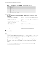
... NN Auxiliary chassis fan header OO Board status LEDs PP Front panel audio header Online Support For more information on supported processors for Intel Desktop Board DZ68BC • Supported processors http://ark.intel.com http://processormatch.intel.com • Chipset information http://www.intel.com/products/desktop/chipsets/inde x.htm • BIOS and driver updates http://downloadcenter...
... NN Auxiliary chassis fan header OO Board status LEDs PP Front panel audio header Online Support For more information on supported processors for Intel Desktop Board DZ68BC • Supported processors http://ark.intel.com http://processormatch.intel.com • Chipset information http://www.intel.com/products/desktop/chipsets/inde x.htm • BIOS and driver updates http://downloadcenter...
Product Guide
Page 15
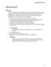
and dual-channel memory interleaving • Unbuffered, non-registered single- These operating systems will report less than 1.65 V may damage the processor. • Non-ECC DDR3 memory • Serial Presence Detect (SPD) memory only • Up to 32 GB maximum total system memory using ...-plated contacts arranged in graphics cards and other system resources. 15 Desktop Board Features Main Memory NOTE To be fully compliant with all applicable Intel ® SDRAM memory specifications, the board should be populated with a voltage rating higher than 4 GB because of the memory used by ...
and dual-channel memory interleaving • Unbuffered, non-registered single- These operating systems will report less than 1.65 V may damage the processor. • Non-ECC DDR3 memory • Serial Presence Detect (SPD) memory only • Up to 32 GB maximum total system memory using ...-plated contacts arranged in graphics cards and other system resources. 15 Desktop Board Features Main Memory NOTE To be fully compliant with all applicable Intel ® SDRAM memory specifications, the board should be populated with a voltage rating higher than 4 GB because of the memory used by ...
Product Guide
Page 23
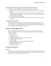
... power supply voltages to detect levels above and below acceptable values • Smart fan control provided by the legacy I /O controller. • A thermal sensor in the processor • Thermally monitored closed-loop fan control, for the location of the chassis intrusion header. optimized thermal management.
... power supply voltages to detect levels above and below acceptable values • Smart fan control provided by the legacy I /O controller. • A thermal sensor in the processor • Thermally monitored closed-loop fan control, for the location of the chassis intrusion header. optimized thermal management.
Product Guide
Page 24
... the power supply must be set by using this feature can damage the power supply. Intel Desktop Board DZ68BC Product Guide Hardware Support Power Connectors ATX12V-compliant power supplies can turn off ). The Desktop Board has a 4-pin processor fan header and three 4-pin chassis fan headers. The LAN subsystem monitors network traffic and...
... the power supply must be set by using this feature can damage the power supply. Intel Desktop Board DZ68BC Product Guide Hardware Support Power Connectors ATX12V-compliant power supplies can turn off ). The Desktop Board has a 4-pin processor fan header and three 4-pin chassis fan headers. The LAN subsystem monitors network traffic and...
Product Guide
Page 28
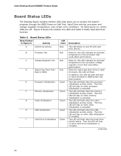
...when the memory initialization activity starts. This LED will flash when the processor initialization activity starts. Then the LED will light and stay on when USB initialization is complete. Intel Desktop Board DZ68BC Product Guide Board Status LEDs The Desktop Board includes thirteen LEDs that ...allow you to monitor the board's progress through the BIOS Power-on the processor that could affect performance. When lit, this...
...when the memory initialization activity starts. This LED will flash when the processor initialization activity starts. Then the LED will light and stay on when USB initialization is complete. Intel Desktop Board DZ68BC Product Guide Board Status LEDs The Desktop Board includes thirteen LEDs that ...allow you to monitor the board's progress through the BIOS Power-on the processor that could affect performance. When lit, this...
Product Guide
Page 31
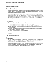
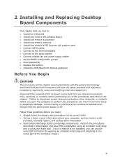
... Replacing Desktop Board Components This chapter tells you how to: • Install the I/O shield • Install and remove the Desktop Board • Install and remove a processor • Install and remove memory • Install and remove a PCI Express x16 graphics card • Connect SATA cables • Connect to the internal headers •...
... Replacing Desktop Board Components This chapter tells you how to: • Install the I/O shield • Install and remove the Desktop Board • Install and remove a processor • Install and remove memory • Install and remove a PCI Express x16 graphics card • Connect SATA cables • Connect to the internal headers •...
Product Guide
Page 32
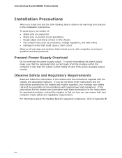
...8226; Sharp pins on printed circuit assemblies • Rough edges and sharp corners on the chassis • Hot components (such as processors, voltage regulators, and heat sinks) • Damage to find out how you can ensure that the calculated total current loads of all...instructions. For information about the Desktop Board's regulatory compliance, refer to qualified technical personnel. Intel Desktop Board DZ68BC Product Guide Installation Precautions When you install and test the Intel Desktop Board, observe all warnings and cautions in this section and the instructions supplied with the...
...8226; Sharp pins on printed circuit assemblies • Rough edges and sharp corners on the chassis • Hot components (such as processors, voltage regulators, and heat sinks) • Damage to find out how you can ensure that the calculated total current loads of all...instructions. For information about the Desktop Board's regulatory compliance, refer to qualified technical personnel. Intel Desktop Board DZ68BC Product Guide Installation Precautions When you install and test the Intel Desktop Board, observe all warnings and cautions in this section and the instructions supplied with the...
Product Guide
Page 35
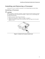
... been removed by pushing it down and away from the computer. Figure 9. Unlatch the Processor Socket Lever 35 Observe the precautions in "Before You Begin" on page 31. 2. To install a processor, follow these instructions: 1. Failure to install the processor on the Desktop Board are given below. Installing and Replacing Desktop Board Components Installing...
... been removed by pushing it down and away from the computer. Figure 9. Unlatch the Processor Socket Lever 35 Observe the precautions in "Before You Begin" on page 31. 2. To install a processor, follow these instructions: 1. Failure to install the processor on the Desktop Board are given below. Installing and Replacing Desktop Board Components Installing...
Product Guide
Page 36
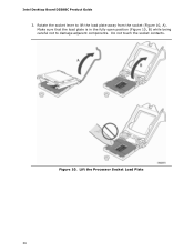
Figure 10. Do not touch the socket contacts. Make sure that the load plate is in the fully open position (Figure 10, B) while being careful not to lift the load plate away from the socket (Figure 10, A). Lift the Processor Socket Load Plate 36 Rotate the socket lever to damage adjacent components. Intel Desktop Board DZ68BC Product Guide 3.
Figure 10. Do not touch the socket contacts. Make sure that the load plate is in the fully open position (Figure 10, B) while being careful not to lift the load plate away from the socket (Figure 10, A). Lift the Processor Socket Load Plate 36 Rotate the socket lever to damage adjacent components. Intel Desktop Board DZ68BC Product Guide 3.
Product Guide
Page 37
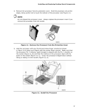
... edges, being careful not to align your fingers with the posts on the processor align with the socket finger cutouts. Install the Processor 37 Remove the processor from the socket. Make sure that the processor Pin 1 indicator (gold triangle) is aligned with the Pin 1 chamfer on... the socket (Figure 12, C). NOTE Do not discard the processor cover. Always replace the processor cover if you remove the processor from its protective cover. Remove the Processor from the Protective Cover 5. Lower the processor straight down without tilting or sliding it in Figure 12 to touch...
... edges, being careful not to align your fingers with the posts on the processor align with the socket finger cutouts. Install the Processor 37 Remove the processor from the socket. Make sure that the processor Pin 1 indicator (gold triangle) is aligned with the Pin 1 chamfer on... the socket (Figure 12, C). NOTE Do not discard the processor cover. Always replace the processor cover if you remove the processor from its protective cover. Remove the Processor from the Protective Cover 5. Lower the processor straight down without tilting or sliding it in Figure 12 to touch...
Product Guide
Page 38
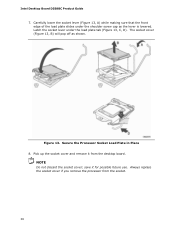
... that the front edge of the load plate slides under the load plate tab (Figure 13, C, D). Always replace the socket cover if you remove the processor from the desktop board. NOTE Do not discard the socket cover; Latch the socket lever under the shoulder screw cap as shown. Figure 13. save... it from the socket. 38 The socket cover (Figure 13, B) will pop off as the lever is lowered. Intel Desktop Board DZ68BC Product Guide 7. Secure the Processor Socket Load Plate in Place 8.
... that the front edge of the load plate slides under the load plate tab (Figure 13, C, D). Always replace the socket cover if you remove the processor from the desktop board. NOTE Do not discard the socket cover; Latch the socket lever under the shoulder screw cap as shown. Figure 13. save... it from the socket. 38 The socket cover (Figure 13, B) will pop off as the lever is lowered. Intel Desktop Board DZ68BC Product Guide 7. Secure the Processor Socket Load Plate in Place 8.
Product Guide
Page 39
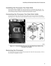
... heat sink to the Desktop Board, refer to the boxed processor manual or boxed thermal solution manual. For instructions on how to remove the processor fan heat sink and processor, refer to the 4-pin processor fan header (see Figure 14). A fan with a 4-pin connector...recommended. Figure 14. Connecting the Processor Fan Heat Sink Cable Connect the processor fan heat sink power cable to the processor installation manual. 39 Installing and Replacing Desktop Board Components Installing the Processor Fan Heat Sink Intel Desktop Board DZ68BC has mounting holes for a processor fan heat sink.
... heat sink to the Desktop Board, refer to the boxed processor manual or boxed thermal solution manual. For instructions on how to remove the processor fan heat sink and processor, refer to the 4-pin processor fan header (see Figure 14). A fan with a 4-pin connector...recommended. Figure 14. Connecting the Processor Fan Heat Sink Cable Connect the processor fan heat sink power cable to the processor installation manual. 39 Installing and Replacing Desktop Board Components Installing the Processor Fan Heat Sink Intel Desktop Board DZ68BC has mounting holes for a processor fan heat sink.
Product Guide
Page 57
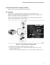
... 2 x 4 pin connector (Figure 27, A). 3. The 2 x 12 pin main power connector (Figure 27, B) is backwards compatible with ATX12V power supplies with 2 x 10 connectors. Connect the 12 V processor core voltage power supply cable to the 2 x 12 pin connector (Figure 27, B). 57 Installing and Replacing Desktop Board Components Connecting Power Supply Cables Figure 27...
... 2 x 4 pin connector (Figure 27, A). 3. The 2 x 12 pin main power connector (Figure 27, B) is backwards compatible with ATX12V power supplies with 2 x 10 connectors. Connect the 12 V processor core voltage power supply cable to the 2 x 12 pin connector (Figure 27, B). 57 Installing and Replacing Desktop Board Components Connecting Power Supply Cables Figure 27...
Product Guide
Page 71
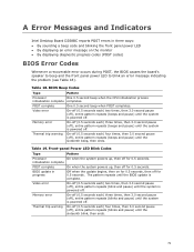
A Error Messages and Indicators Intel Desktop Board DZ68BC reports POST errors in progress Video error Off when the update begins, then on the monitor • By displaying diagnostic progress codes (POST codes) BIOS ... the system is powered off ), entire pattern repeats (blinks and pause) until the system is powered off . Front-panel Power LED Blink Codes Type Pattern Processor On when the system powers up , then off for 0.5 seconds. Table 19. Video error On-off (0.5 seconds each ) four times, then 3.0 second pause (off . BIOS...
A Error Messages and Indicators Intel Desktop Board DZ68BC reports POST errors in progress Video error Off when the update begins, then on the monitor • By displaying diagnostic progress codes (POST codes) BIOS ... the system is powered off ), entire pattern repeats (blinks and pause) until the system is powered off . Front-panel Power LED Blink Codes Type Pattern Processor On when the system powers up , then off for 0.5 seconds. Table 19. Video error On-off (0.5 seconds each ) four times, then 3.0 second pause (off . BIOS...
Product Guide
Page 72
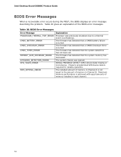
...shutdown due to the amount of the BIOS error messages. Intel Desktop Board DZ68BC Product Guide BIOS Error Messages When a recoverable error occurs... during the POST, the BIOS displays an error message describing the problem. The firmware has detected that the system memory has decreased. BIOS Error Messages Error Message PROCESSOR_THERMAL_TRIP_ERROR CMOS_BATTERY_ERROR CMOS_CHECKSUM_ERROR CMOS_TIMER_ERROR MEMORY_SIZE_DECREASE_ERROR INTRUDER_DETECTION_ERROR SPD_TOLER_ERROR MEM_OPTIMAL_ERROR Explanation Processor...
...shutdown due to the amount of the BIOS error messages. Intel Desktop Board DZ68BC Product Guide BIOS Error Messages When a recoverable error occurs... during the POST, the BIOS displays an error message describing the problem. The firmware has detected that the system memory has decreased. BIOS Error Messages Error Message PROCESSOR_THERMAL_TRIP_ERROR CMOS_BATTERY_ERROR CMOS_CHECKSUM_ERROR CMOS_TIMER_ERROR MEMORY_SIZE_DECREASE_ERROR INTRUDER_DETECTION_ERROR SPD_TOLER_ERROR MEM_OPTIMAL_ERROR Explanation Processor...


