
Product Guide
Page 5
...1 Desktop Board Features Supported Operating Systems 11 Desktop Board Components 12 Processor ...14 Main Memory...15 Intel® Z68 Express Chipset 16 Intel® Rapid Storage Technology 16 Intel® Smart Response Technology 16 Audio Subsystem 16 LAN Subsystem 17 USB Support ...18 SATA Support...18... BIOS Button 22 Hardware Management 22 Hardware Monitoring and Fan Speed Control 23 Chassis Intrusion 23 Power Management 23 Software Support 23 ACPI 23 Hardware Support 24 Power Connectors 24 Fan Headers 24 LAN Wake Capabilities 24 Instantly Available PC Technology 25 Standby...
...1 Desktop Board Features Supported Operating Systems 11 Desktop Board Components 12 Processor ...14 Main Memory...15 Intel® Z68 Express Chipset 16 Intel® Rapid Storage Technology 16 Intel® Smart Response Technology 16 Audio Subsystem 16 LAN Subsystem 17 USB Support ...18 SATA Support...18... BIOS Button 22 Hardware Management 22 Hardware Monitoring and Fan Speed Control 23 Chassis Intrusion 23 Power Management 23 Software Support 23 ACPI 23 Hardware Support 24 Power Connectors 24 Fan Headers 24 LAN Wake Capabilities 24 Instantly Available PC Technology 25 Standby...
Product Guide
Page 6
Intel Desktop Board DZ68BC Product Guide 2 Installing and Replacing Desktop Board Components Before You Begin 31 Installation Precautions 32 Prevent Power Supply Overload 32 Observe Safety and Regulatory Requirements 32 Installing the I/O Shield 33 Installing and Removing the Desktop Board 34...Chassis Fan Cables 56 Connecting Power Supply Cables 57 Setting the BIOS Configuration Jumper 58 Clearing Passwords 59 Replacing the Battery 60 Installing the WiFi/Bluetooth* Module in a Desktop Chassis (Optional 66 3 Updating the BIOS Updating the BIOS with the Intel® Express BIOS Update ...
Intel Desktop Board DZ68BC Product Guide 2 Installing and Replacing Desktop Board Components Before You Begin 31 Installation Precautions 32 Prevent Power Supply Overload 32 Observe Safety and Regulatory Requirements 32 Installing the I/O Shield 33 Installing and Removing the Desktop Board 34...Chassis Fan Cables 56 Connecting Power Supply Cables 57 Setting the BIOS Configuration Jumper 58 Clearing Passwords 59 Replacing the Battery 60 Installing the WiFi/Bluetooth* Module in a Desktop Chassis (Optional 66 3 Updating the BIOS Updating the BIOS with the Intel® Express BIOS Update ...
Product Guide
Page 7
... Sink Power Cable to BIOS Button 22 4. Connecting SATA Cables 48 24. Remove the Processor from the Protective Cover 37 12. Example Dual Channel Memory Configuration with Four DIMMs 41 17. Intel Desktop Board DZ68BC Mounting Screw Hole Locations 34 9. Intel Desktop Board DZ68BC Components... Ensure Electromagnetic Compatibility (EMC) Compliance 85 Product Certifications 86 Board-Level Certifications 86 Chassis- Install the Processor 37 13. Onboard Power and Reset Buttons 27 6. Secure the Processor Socket Load Plate in Place 38 14. Installing a DIMM 43 20. Unlatch...
... Sink Power Cable to BIOS Button 22 4. Connecting SATA Cables 48 24. Remove the Processor from the Protective Cover 37 12. Example Dual Channel Memory Configuration with Four DIMMs 41 17. Intel Desktop Board DZ68BC Mounting Screw Hole Locations 34 9. Intel Desktop Board DZ68BC Components... Ensure Electromagnetic Compatibility (EMC) Compliance 85 Product Certifications 86 Board-Level Certifications 86 Chassis- Install the Processor 37 13. Onboard Power and Reset Buttons 27 6. Secure the Processor Socket Load Plate in Place 38 14. Installing a DIMM 43 20. Unlatch...
Product Guide
Page 8
... Names 50 9. Back Panel CIR Header Emitter (Output) Header Signal Names 52 12. Intel Desktop Board DZ68BC China RoHS Material Self Declaration Table 82 Tables 1. LAN Connector LEDs 18 5. Front Panel Intel HD Audio Header Signal Names 50 7. Front Panel Header Signal Names 52 13. USB ...2.0 Header Signal Names 53 16. Front-panel Power LED Blink Codes 71 20. Regulatory ...
... Names 50 9. Back Panel CIR Header Emitter (Output) Header Signal Names 52 12. Intel Desktop Board DZ68BC China RoHS Material Self Declaration Table 82 Tables 1. LAN Connector LEDs 18 5. Front Panel Intel HD Audio Header Signal Names 50 7. Front Panel Header Signal Names 52 13. USB ...2.0 Header Signal Names 53 16. Front-panel Power LED Blink Codes 71 20. Regulatory ...
Product Guide
Page 10
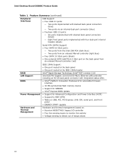
Intel Desktop Board DZ68BC Product Guide Table 1. Feature Summary (continued) Peripheral Interfaces USB Support: • ...internal headers (black) Serial ATA (SATA) Support: • Four SATA 6.0 Gb/s ports: ― Two ports from the Intel Z68 PCH (dark blue) ― Two ports from an onboard Marvell controller (light blue) • Four SATA 3.0 Gb...interface • 32 Mb symmetrical flash memory device • Support for SMBIOS • Intel® Express BIOS Update • Support for Advanced Configuration and Power Interface (ACPI) • Suspend to RAM (STR) • Wake on USB, PCI...
Intel Desktop Board DZ68BC Product Guide Table 1. Feature Summary (continued) Peripheral Interfaces USB Support: • ...internal headers (black) Serial ATA (SATA) Support: • Four SATA 6.0 Gb/s ports: ― Two ports from the Intel Z68 PCH (dark blue) ― Two ports from an onboard Marvell controller (light blue) • Four SATA 3.0 Gb...interface • 32 Mb symmetrical flash memory device • Support for SMBIOS • Intel® Express BIOS Update • Support for Advanced Configuration and Power Interface (ACPI) • Suspend to RAM (STR) • Wake on USB, PCI...

Product Guide
Page 13
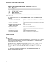
Desktop Board Features Table 2. Intel Desktop Board DZ68BC Components Label Description A PCI bus connector B PCI bus connector C S/PDIF header D PCI Express 2.0 x16 connector (x8 electrical; x16 compatible) E Speaker F PCI ...(input) header T Back panel CIR transmitter (output) header U Main power connector (2 x 12 pin) V Standby power indicator LED W Onboard reset button X Onboard power button Y Front panel header Z Front chassis fan header AA Alternate front panel power LED header BB Intel Z68 PCH CC Battery DD Two 6.0 Gb/s SATA ports (Marvell controller)...
Desktop Board Features Table 2. Intel Desktop Board DZ68BC Components Label Description A PCI bus connector B PCI bus connector C S/PDIF header D PCI Express 2.0 x16 connector (x8 electrical; x16 compatible) E Speaker F PCI ...(input) header T Back panel CIR transmitter (output) header U Main power connector (2 x 12 pin) V Standby power indicator LED W Onboard reset button X Onboard power button Y Front panel header Z Front chassis fan header AA Alternate front panel power LED header BB Intel Z68 PCH CC Battery DD Two 6.0 Gb/s SATA ports (Marvell controller)...
Product Guide
Page 14
.../p/en_US/support?iid=hdr+supp ort • Available configurations for Intel Desktop Board DZ68BC, go /buildit Processor CAUTION Failure to use an appropriate power supply and/or not connecting the 12 V (2 x 4 pin) power connector to http://processormatch.intel.com. 14 Intel Desktop Board DZ68BC supports an Intel processor in damage to the Desktop Board through the LGA1155 socket...
.../p/en_US/support?iid=hdr+supp ort • Available configurations for Intel Desktop Board DZ68BC, go /buildit Processor CAUTION Failure to use an appropriate power supply and/or not connecting the 12 V (2 x 4 pin) power connector to http://processormatch.intel.com. 14 Intel Desktop Board DZ68BC supports an Intel processor in damage to the Desktop Board through the LGA1155 socket...
Product Guide
Page 15
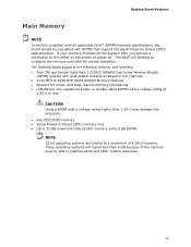
Desktop Board Features Main Memory NOTE To be fully compliant with all applicable Intel ® SDRAM memory specifications, the board should be populated with gold-plated contacts arranged in graphics cards and other system resources. 15 or double-sided ...; Up to 32 GB maximum total system memory using 8 GB DIMMs NOTE 32-bit operating systems are limited to this effect on the screen at power up.
Desktop Board Features Main Memory NOTE To be fully compliant with all applicable Intel ® SDRAM memory specifications, the board should be populated with gold-plated contacts arranged in graphics cards and other system resources. 15 or double-sided ...; Up to 32 GB maximum total system memory using 8 GB DIMMs NOTE 32-bit operating systems are limited to this effect on the screen at power up.
Product Guide
Page 17
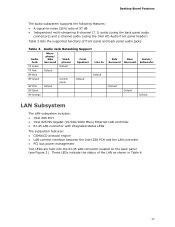
...Default BP Black BP Orange Side Rear Center/ Surround Surround Subwoofer Default Default Default LAN Subsystem The LAN subsystem includes: • Intel Z68 PCH • Intel 82579V Gigabit (10/100/1000 Mb/s) Ethernet LAN controller • RJ-45 LAN connector with integrated status LEDs The subsystem features...: • CSMA/CD protocol engine • LAN connect interface between the Intel Z68 PCH and the LAN controller • PCI bus power management Two LEDs are built into the RJ-45 LAN connector located on the back panel (see Figure ...
...Default BP Black BP Orange Side Rear Center/ Surround Surround Subwoofer Default Default Default LAN Subsystem The LAN subsystem includes: • Intel Z68 PCH • Intel 82579V Gigabit (10/100/1000 Mb/s) Ethernet LAN controller • RJ-45 LAN connector with integrated status LEDs The subsystem features...: • CSMA/CD protocol engine • LAN connect interface between the Intel Z68 PCH and the LAN controller • PCI bus power management Two LEDs are built into the RJ-45 LAN connector located on the back panel (see Figure ...
Product Guide
Page 19
... (CIR) support • Serial port support via an onboard header • Low pin count (LPC) interface • Intelligent power management, including a programmable wake up event interface • PCI power management support Expandability Intel Desktop Board DZ68BC provides the following RAID (Redundant Array of Independent Drives) levels: • RAID 0 - data striping • RAID 1 - data mirroring...
... (CIR) support • Serial port support via an onboard header • Low pin count (LPC) interface • Intelligent power management, including a programmable wake up event interface • PCI power management support Expandability Intel Desktop Board DZ68BC provides the following RAID (Redundant Array of Independent Drives) levels: • RAID 0 - data striping • RAID 1 - data mirroring...
Product Guide
Page 21
... a Serial Peripheral Interface (SPI) Flash device. You do not need to Clearing Passwords on page 59. 21 Desktop Board Features BIOS The BIOS provides the Power-On Self-Test (POST), the BIOS Setup program, and the PCI/PCI Express and SATA auto-configuration utilities. Related Links: For instructions on resetting the...
... a Serial Peripheral Interface (SPI) Flash device. You do not need to Clearing Passwords on page 59. 21 Desktop Board Features BIOS The BIOS provides the Power-On Self-Test (POST), the BIOS Setup program, and the PCI/PCI Express and SATA auto-configuration utilities. Related Links: For instructions on resetting the...
Product Guide
Page 22
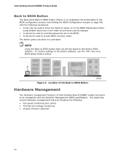
... set the board to be used to invoke BIOS recovery mode. Intel Desktop Board DZ68BC Product Guide Back to BIOS Button The back panel Back to BIOS button (Figure 3, A) duplicates the functionality of Intel Desktop Board DZ68BC enable the board to the factory BIOS defaults. The board has... several hardware management features including the following exceptions: • It can only be used to force the board to power on page 58) with the Wired for ...
... set the board to be used to invoke BIOS recovery mode. Intel Desktop Board DZ68BC Product Guide Back to BIOS Button The back panel Back to BIOS button (Figure 3, A) duplicates the functionality of Intel Desktop Board DZ68BC enable the board to the factory BIOS defaults. The board has... several hardware management features including the following exceptions: • It can only be used to force the board to power on page 58) with the Wired for ...
Product Guide
Page 23
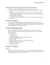
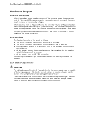
.... Desktop Board Features Hardware Monitoring and Fan Speed Control The features of the hardware monitoring and fan speed control include: • Monitoring of power supply voltages to detect levels above and below acceptable values • Smart fan control provided by the legacy I /O controller. • A...chassis intrusion header. See Figure 24, D for all onboard fans, that can be connected to RAM) • Standby Power Indicator LED • Wake from USB • Power Management Event signal (PME#) wakeup support • WAKE# signal wake-up support • Wake from Consumer IR •...
.... Desktop Board Features Hardware Monitoring and Fan Speed Control The features of the hardware monitoring and fan speed control include: • Monitoring of power supply voltages to detect levels above and below acceptable values • Smart fan control provided by the legacy I /O controller. • A...chassis intrusion header. See Figure 24, D for all onboard fans, that can be connected to RAM) • Standby Power Indicator LED • Wake from USB • Power Management Event signal (PME#) wakeup support • WAKE# signal wake-up support • Wake from Consumer IR •...
Product Guide
Page 24
... CAUTION For LAN wake capabilities, the 5 V standby line for the location of the power connectors. Failure to the power state it asserts a wake-up of the computer through system control. Intel Desktop Board DZ68BC Product Guide Hardware Support Power Connectors ATX12V-compliant power supplies can turn off as follows: • The fans are on when the...
... CAUTION For LAN wake capabilities, the 5 V standby line for the location of the power connectors. Failure to the power state it asserts a wake-up of the computer through system control. Intel Desktop Board DZ68BC Product Guide Hardware Support Power Connectors ATX12V-compliant power supplies can turn off as follows: • The fans are on when the...
Product Guide
Page 25
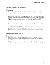
...board to do so could damage the board and any devices connected to provide adequate standby current when using this specification can damage the power supply and/or effect ACPI S3 sleep state functionality. When signaled by the LED turning amber. Failure to enter the ACPI S3 (Suspend... sleep state is indicated by a wake-up device or event, the computer quickly returns to be off. Standby Power Indicator LED CAUTION If the AC power has been switched off . Power supplies used to support the standard Instantly Available (ACPI S3 sleep state) configuration. If the computer has a dual...
...board to do so could damage the board and any devices connected to provide adequate standby current when using this specification can damage the power supply and/or effect ACPI S3 sleep state functionality. When signaled by the LED turning amber. Failure to enter the ACPI S3 (Suspend... sleep state is indicated by a wake-up device or event, the computer quickly returns to be off. Standby Power Indicator LED CAUTION If the AC power has been switched off . Power supplies used to support the standard Instantly Available (ACPI S3 sleep state) configuration. If the computer has a dual...
Product Guide
Page 26
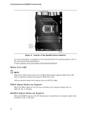
Intel Desktop Board DZ68BC Product Guide Figure 4. PME# Signal Wake-up Support When the WAKE# signal on the PCI bus is asserted, the computer wakes from an ACPI S3, ... wakes from an ACPI S3, S4, or S5 state. 26 Location of the Standby Power Indicator For more information on standby current requirements for the Desktop Board, refer to the Technical Product Specification at http://support.intel.com/support/motherboards/desktop/ Wake from USB NOTE Wake from USB requires the use of...
Intel Desktop Board DZ68BC Product Guide Figure 4. PME# Signal Wake-up Support When the WAKE# signal on the PCI bus is asserted, the computer wakes from an ACPI S3, ... wakes from an ACPI S3, S4, or S5 state. 26 Location of the Standby Power Indicator For more information on standby current requirements for the Desktop Board, refer to the Technical Product Specification at http://support.intel.com/support/motherboards/desktop/ Wake from USB NOTE Wake from USB requires the use of...
Product Guide
Page 27
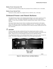
... from an ACPI S3, S4, or S5 state. To turn the computer on the Desktop Board (Figure 5, B) can be off the computer using the onboard Power button, press it for three seconds. Failure to turn off . The lighted Reset button on or off and the onboard... on the Desktop Board (Figure 5, A) can be used to the board. For example, when this button is lit, standby power is the case even when the computer appears to be used to do so could damage the board and any devices connected to reset the ...
... from an ACPI S3, S4, or S5 state. To turn the computer on the Desktop Board (Figure 5, B) can be off the computer using the onboard Power button, press it for three seconds. Failure to turn off . The lighted Reset button on or off and the onboard... on the Desktop Board (Figure 5, A) can be used to the board. For example, when this button is lit, standby power is the case even when the computer appears to be used to do so could damage the board and any devices connected to reset the ...
Product Guide
Page 28
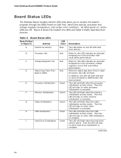
...is complete. When lit, this LED indicates an elevated temperature on when the Back to monitor the board's progress through the BIOS Power-on when processor initialization is complete. This LED will flash when the memory initialization activity starts. Then the LED will stay on...starts. This LED will flash when the hard drive activity starts. This LED will flash when the video initialization activity starts. Intel Desktop Board DZ68BC Product Guide Board Status LEDs The Desktop Board includes thirteen LEDs that could affect performance. This LED will stay on Self-Test...
...is complete. When lit, this LED indicates an elevated temperature on when the Back to monitor the board's progress through the BIOS Power-on when processor initialization is complete. This LED will flash when the memory initialization activity starts. Then the LED will stay on...starts. This LED will flash when the hard drive activity starts. This LED will flash when the video initialization activity starts. Intel Desktop Board DZ68BC Product Guide Board Status LEDs The Desktop Board includes thirteen LEDs that could affect performance. This LED will stay on Self-Test...
Product Guide
Page 30
Battery A battery on the Desktop Board keeps the values in CMOS RAM and the clock current when the computer is turned off . 30 Intel Desktop Board DZ68BC Product Guide Speaker A speaker is turned off . The battery on the Desktop Board keeps the clock current when the computer is mounted on how to .... Refer to Appendix A for instructions on the Desktop Board. Go to replace the battery. The speaker provides audible error code (beep code) information during the Power-On Self-Test (POST).
Battery A battery on the Desktop Board keeps the values in CMOS RAM and the clock current when the computer is turned off . 30 Intel Desktop Board DZ68BC Product Guide Speaker A speaker is turned off . The battery on the Desktop Board keeps the clock current when the computer is mounted on how to .... Refer to Appendix A for instructions on the Desktop Board. Go to replace the battery. The speaker provides audible error code (beep code) information during the Power-On Self-Test (POST).
Product Guide
Page 31
... an antistatic wrist strap and attaching it to a metal part of the procedures described in this chapter. Disconnect the computer from its power source and from any telecommunications links, networks, or modems before you open the computer or perform any of the computer chassis. 31...graphics card • Connect SATA cables • Connect to the internal headers • Connect to the audio system • Connect chassis fan and power supply cables • Set the BIOS configuration jumper • Clear passwords • Replace the battery • Install the WiFi/BlueTooth Module (optional...
... an antistatic wrist strap and attaching it to a metal part of the procedures described in this chapter. Disconnect the computer from its power source and from any telecommunications links, networks, or modems before you open the computer or perform any of the computer chassis. 31...graphics card • Connect SATA cables • Connect to the internal headers • Connect to the audio system • Connect chassis fan and power supply cables • Set the BIOS configuration jumper • Clear passwords • Replace the battery • Install the WiFi/BlueTooth Module (optional...

