
Product Guide
Page 5
Contents 1 Desktop Board Features Supported Operating Systems 10 Desktop Board Components 11 Processor ...13 Main Memory...14 Intel® X48 Express Chipset 15 Audio Subsystem 15 LAN Subsystem 16 USB 2.0 Support 17 Enhanced IDE Interface 17 Serial ATA...17 Legacy I/O...Capable 23 Onboard Power Button 24 Onboard VR and CPU LEDs 25 Speaker...25 Battery ...26 Real-Time Clock 26 2 Installing and Replacing Desktop Board Components Before You Begin 27 Installation Precautions 28 Prevent Power Supply Overload 28 Observe Safety and Regulatory Requirements 28 Installing the I/O Shield 29 ...
Contents 1 Desktop Board Features Supported Operating Systems 10 Desktop Board Components 11 Processor ...13 Main Memory...14 Intel® X48 Express Chipset 15 Audio Subsystem 15 LAN Subsystem 16 USB 2.0 Support 17 Enhanced IDE Interface 17 Serial ATA...17 Legacy I/O...Capable 23 Onboard Power Button 24 Onboard VR and CPU LEDs 25 Speaker...25 Battery ...26 Real-Time Clock 26 2 Installing and Replacing Desktop Board Components Before You Begin 27 Installation Precautions 28 Prevent Power Supply Overload 28 Observe Safety and Regulatory Requirements 28 Installing the I/O Shield 29 ...
Product Guide
Page 6
Intel Desktop Board DX48BT2 Product Guide Installing and Removing a Processor 31 Installing a Processor 31 Installing the Processor Fan Heat Sink 35 Connecting the Processor Fan Heat Sink Cable 35 Removing the Processor 36 Installing the ICH Heat Sink Decorative Cover (Optional 36 Installing an MCH Heat Sink Fan (Optional 37...Setting the BIOS Configuration Jumper 56 Clearing Passwords 57 Replacing the Battery 58 3 Updating the BIOS Updating the BIOS with the Intel® Express BIOS Update Utility 63 Updating the BIOS with the ISO Image BIOS Update File or the Iflash Memory Update ...
Intel Desktop Board DX48BT2 Product Guide Installing and Removing a Processor 31 Installing a Processor 31 Installing the Processor Fan Heat Sink 35 Connecting the Processor Fan Heat Sink Cable 35 Removing the Processor 36 Installing the ICH Heat Sink Decorative Cover (Optional 36 Installing an MCH Heat Sink Fan (Optional 37...Setting the BIOS Configuration Jumper 56 Clearing Passwords 57 Replacing the Battery 58 3 Updating the BIOS Updating the BIOS with the Intel® Express BIOS Update Utility 63 Updating the BIOS with the ISO Image BIOS Update File or the Iflash Memory Update ...

Product Guide
Page 7
... Express x16 Card 45 vii Install the Processor 33 13. Installation of the Standby Power Indicator 22 4. Installing the I/O Shield 29 7. Dual Channel Memory Configuration with Two DIMMs 38 18. Installing a DIMM 41 22. Desktop Board DX48BT2 Components 11 2. Dual Channel Memory Configuration ...Statement 74 Product Ecology Statements 75 Recycling Considerations 75 Lead-free 2LI/Pb-free 2LI Board 78 Restriction of the VR and CPU LEDs 25 6. Desktop Board DX48BT2 Mounting Screw Hole Locations 30 8. Remove the Protective Socket Cover 32 11. LAN Connector...
... Express x16 Card 45 vii Install the Processor 33 13. Installation of the Standby Power Indicator 22 4. Installing the I/O Shield 29 7. Dual Channel Memory Configuration with Two DIMMs 38 18. Installing a DIMM 41 22. Desktop Board DX48BT2 Components 11 2. Dual Channel Memory Configuration ...Statement 74 Product Ecology Statements 75 Recycling Considerations 75 Lead-free 2LI/Pb-free 2LI Board 78 Restriction of the VR and CPU LEDs 25 6. Desktop Board DX48BT2 Mounting Screw Hole Locations 30 8. Remove the Protective Socket Cover 32 11. LAN Connector...

Product Guide
Page 9
...; processor in the LGA775 package • Four 240-pin, DDR3 1.5 V SDRAM Dual Inline Memory Module (DIMM) sockets • 1600/1333/1066/800 MHz DDR3 SDRAM interface • Support for up to 8 GB of system memory Intel® X48 Express Chipset consisting of the Desktop Board. 1 Desktop Board Features This chapter briefly describes the features of Intel® Desktop Board DX48BT2.
...; processor in the LGA775 package • Four 240-pin, DDR3 1.5 V SDRAM Dual Inline Memory Module (DIMM) sockets • 1600/1333/1066/800 MHz DDR3 SDRAM interface • Support for up to 8 GB of system memory Intel® X48 Express Chipset consisting of the Desktop Board. 1 Desktop Board Features This chapter briefly describes the features of Intel® Desktop Board DX48BT2.
Product Guide
Page 12
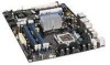
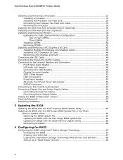
...connector Front panel audio header PCI Express 2.0 x16 primary connector Rear chassis fan header (3-pin) MCH fan header (3-pin) Back panel connectors 12 V processor core voltage connector (2 x 4 pin) Processor socket Processor fan header (4-pin) DDR3 DIMM 0 sockets DDR3 DIMM 1 sockets IDE connector Main power connector (2 x 12 pin) Front chassis fan header (3-pin)... Back panel CIR transmitter (output) header Front panel header High Definition Audio Link header Auxiliary PCI Express graphics power connector (1 x 4 pin) S/PDIF connector 12 Intel Desktop Board DX48BT2 Product Guide Table 2.
...connector Front panel audio header PCI Express 2.0 x16 primary connector Rear chassis fan header (3-pin) MCH fan header (3-pin) Back panel connectors 12 V processor core voltage connector (2 x 4 pin) Processor socket Processor fan header (4-pin) DDR3 DIMM 0 sockets DDR3 DIMM 1 sockets IDE connector Main power connector (2 x 12 pin) Front chassis fan header (3-pin)... Back panel CIR transmitter (output) header Front panel header High Definition Audio Link header Auxiliary PCI Express graphics power connector (1 x 4 pin) S/PDIF connector 12 Intel Desktop Board DX48BT2 Product Guide Table 2.
Product Guide
Page 13
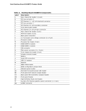
... about : • Instructions on installing or upgrading the processor, page 31 in Chapter 2 • Supported processors for more information about : • Desktop Board DX48BT2 http://www.intel.com/design/motherbd http://support.intel.com/support/motherboards/ desktop • Supported processors http://www.intel.com/go /findCPU 13 Desktop Board DX48BT2 supports an Intel processor in the LGA775 package. The processor connects to the Desktop Board through the LGA775 socket.
... about : • Instructions on installing or upgrading the processor, page 31 in Chapter 2 • Supported processors for more information about : • Desktop Board DX48BT2 http://www.intel.com/design/motherbd http://support.intel.com/support/motherboards/ desktop • Supported processors http://www.intel.com/go /findCPU 13 Desktop Board DX48BT2 supports an Intel processor in the LGA775 package. The processor connects to the Desktop Board through the LGA775 socket.
Product Guide
Page 15
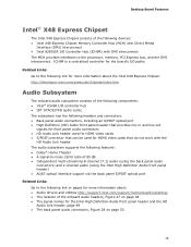
... Link header The audio subsystem supports the following link for more information about: • Audio drivers and utilities http://support.intel.com/support/motherboards/desktop/ • The location of 95 dB • Independent multi-streaming 8-channel (7.1) audio (using the back panel audio ...processor, memory, PCI Express bus, and the DMI interconnect. Related Links: Go to the following features: • Dolby* Home Theater • A signal-to-noise (S/N) ratio of the onboard audio headers, Figure 27 on page 53 15 Desktop Board Features Intel® X48 Express Chipset The Intel...
... Link header The audio subsystem supports the following link for more information about: • Audio drivers and utilities http://support.intel.com/support/motherboards/desktop/ • The location of 95 dB • Independent multi-streaming 8-channel (7.1) audio (using the back panel audio ...processor, memory, PCI Express bus, and the DMI interconnect. Related Links: Go to the following features: • Dolby* Home Theater • A signal-to-noise (S/N) ratio of the onboard audio headers, Figure 27 on page 53 15 Desktop Board Features Intel® X48 Express Chipset The Intel...

Product Guide
Page 17
...the following RAID (Redundant Array of information between the processor and peripheral devices such as CD-ROM drives) • Older PIO Mode devices • Ultra DMA-33 and ATA-66/100 protocols Serial ATA Desktop Board DX48BT2 supports six onboard Serial ATA channels (3.0 Gb/s) via... ICH9R and two eSATA channels (3.0 Gb/s) via the ICH9R. data striping • RAID 1 - distributed parity For information on configuring your system for RAID using Intel® Matrix Storage Technology ...
...the following RAID (Redundant Array of information between the processor and peripheral devices such as CD-ROM drives) • Older PIO Mode devices • Ultra DMA-33 and ATA-66/100 protocols Serial ATA Desktop Board DX48BT2 supports six onboard Serial ATA channels (3.0 Gb/s) via... ICH9R and two eSATA channels (3.0 Gb/s) via the ICH9R. data striping • RAID 1 - distributed parity For information on configuring your system for RAID using Intel® Matrix Storage Technology ...
Product Guide
Page 19
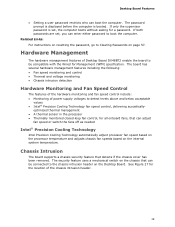
... fan speed or switch the fans off as needed Intel® Precision Cooling Technology Intel Precision Cooling Technology automatically adjust processor fan speed based on the processor temperature and adjusts chassis fan speeds based on page 57. Hardware Management The hardware management features of Desktop Board DX48BT2 enable the board to be connected to Clearing Passwords on the...
... fan speed or switch the fans off as needed Intel® Precision Cooling Technology Intel Precision Cooling Technology automatically adjust processor fan speed based on the processor temperature and adjusts chassis fan speeds based on page 57. Hardware Management The hardware management features of Desktop Board DX48BT2 enable the board to be connected to Clearing Passwords on the...

Product Guide
Page 21
The Desktop Board has a 4-pin processor fan header, one 4-pin and two 3-pin chassis fan headers, and one ... current necessary to support multiple wake events from the PCI and/or USB buses exceeds power supply capacity, the Desktop Board may lose register settings stored in the S3 sleep state, the computer will appear to be capable of delivering ...adequate standby current when using this feature can damage the power supply and/or effect ACPI S3 sleep state functionality. Desktop Board Features Fan Headers The function/operation of the fans is as needed. • All fan headers have a +12...
The Desktop Board has a 4-pin processor fan header, one 4-pin and two 3-pin chassis fan headers, and one ... current necessary to support multiple wake events from the PCI and/or USB buses exceeds power supply capacity, the Desktop Board may lose register settings stored in the S3 sleep state, the computer will appear to be capable of delivering ...adequate standby current when using this feature can damage the power supply and/or effect ACPI S3 sleep state functionality. Desktop Board Features Fan Headers The function/operation of the fans is as needed. • All fan headers have a +12...

Product Guide
Page 25
... codes. 25 Refer to the standby power indicator (see Figure 3), the Desktop Board contains two other LEDs (see Figure 5): • The VR LED (Figure 5, A) indicates an elevated temperature in the processor voltage regulator circuit that could affect performance. Desktop Board Features Onboard VR and CPU LEDs In addition to Appendix A for a description of the VR...
... codes. 25 Refer to the standby power indicator (see Figure 3), the Desktop Board contains two other LEDs (see Figure 5): • The VR LED (Figure 5, A) indicates an elevated temperature in the processor voltage regulator circuit that could affect performance. Desktop Board Features Onboard VR and CPU LEDs In addition to Appendix A for a description of the VR...

Product Guide
Page 27
...to a metal part of the procedures described in this chapter. If such a station is off. Some circuitry on the board can continue to record information about your computer, such as model, serial numbers, installed options, and configuration information. &#...guidelines before performing any procedures can damage components. 2 Installing and Replacing Desktop Board Components This chapter tells you how to: • Install the I/O shield • Install and remove the Desktop Board • Install and remove a processor • Install the ICH heat sink decorative cover • Install ...
...to a metal part of the procedures described in this chapter. If such a station is off. Some circuitry on the board can continue to record information about your computer, such as model, serial numbers, installed options, and configuration information. &#...guidelines before performing any procedures can damage components. 2 Installing and Replacing Desktop Board Components This chapter tells you how to: • Install the I/O shield • Install and remove the Desktop Board • Install and remove a processor • Install the ICH heat sink decorative cover • Install ...
Product Guide
Page 28
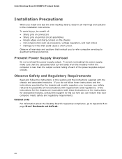
Intel Desktop Board DX48BT2 Product Guide Installation Precautions When you install and test the Intel Desktop Board, observe all warnings and cautions in this section and the instructions supplied with the chassis and associated modules. Prevent Power Supply...output. If you do not follow the instructions in the installation instructions. Related Links For information about the Desktop Board's regulatory compliance, go to Appendix B on the chassis • Hot components (such as processors, voltage regulators, and heat sinks) • Damage to wires that could cause a short circuit Observe...
Intel Desktop Board DX48BT2 Product Guide Installation Precautions When you install and test the Intel Desktop Board, observe all warnings and cautions in this section and the instructions supplied with the chassis and associated modules. Prevent Power Supply...output. If you do not follow the instructions in the installation instructions. Related Links For information about the Desktop Board's regulatory compliance, go to Appendix B on the chassis • Hot components (such as processors, voltage regulators, and heat sinks) • Damage to wires that could cause a short circuit Observe...

Product Guide
Page 31
...Desktop Board Components Installing and Removing a Processor Instructions on how to do so could damage the processor and the board. Installing a Processor CAUTION Before installing or removing a processor, make sure the AC power has been removed by pushing the lever down and away from the computer; Failure to install the processor on the Desktop Board... are given below. Figure 8. Open the socket lever by unplugging the power cord from the socket (Figure 8, A and B). To install a processor, follow these instructions: 1....
...Desktop Board Components Installing and Removing a Processor Instructions on how to do so could damage the processor and the board. Installing a Processor CAUTION Before installing or removing a processor, make sure the AC power has been removed by pushing the lever down and away from the computer; Failure to install the processor on the Desktop Board... are given below. Figure 8. Open the socket lever by unplugging the power cord from the socket (Figure 8, A and B). To install a processor, follow these instructions: 1....

Product Guide
Page 32
Figure 9. Do not discard the protective socket cover. Remove the Protective Socket Cover 32 Lift the Load Plate 4. Intel Desktop Board DX48BT2 Product Guide 3. Figure 10. Do not touch the socket contacts (Figure 9, B). Always replace the socket cover if the processor is removed from the load plate (Figure 10). Remove the plastic protective socket cover from the socket. Lift the load plate (Figure 9, A).
Figure 9. Do not discard the protective socket cover. Remove the Protective Socket Cover 32 Lift the Load Plate 4. Intel Desktop Board DX48BT2 Product Guide 3. Figure 10. Do not touch the socket contacts (Figure 9, B). Always replace the socket cover if the processor is removed from the load plate (Figure 10). Remove the plastic protective socket cover from the socket. Lift the load plate (Figure 9, A).

Product Guide
Page 33
...sliding it in Figure 12. Do not discard the protective processor cover. Figure 12. Figure 11. Align notches (Figure 12, B) with your fingers align to touch the bottom of the processor (see Figure 11). Make sure your thumb and index ...the socket. Remove the Processor from the socket. Always replace the processor cover if the processor is removed from the Protective Processor Cover 6. Hold the processor with the socket (Figure 12, C). Remove the processor from the protective processor cover. Install the Processor 33 Installing and Replacing Desktop Board Components 5.
...sliding it in Figure 12. Do not discard the protective processor cover. Figure 12. Figure 11. Align notches (Figure 12, B) with your fingers align to touch the bottom of the processor (see Figure 11). Make sure your thumb and index ...the socket. Remove the Processor from the socket. Always replace the processor cover if the processor is removed from the Protective Processor Cover 6. Hold the processor with the socket (Figure 12, C). Remove the processor from the protective processor cover. Install the Processor 33 Installing and Replacing Desktop Board Components 5.

Product Guide
Page 35
... 14). Figure 14. however, a fan with a 3-pin connector cannot use the onboard fan control, the fan will always operate at full speed. Installing and Replacing Desktop Board Components Installing the Processor Fan Heat Sink Desktop Board DX48BT2 has mounting holes for a processor fan heat sink. A fan with a 4-pin connector as shown in Figure 14, A is recommended;
... 14). Figure 14. however, a fan with a 3-pin connector cannot use the onboard fan control, the fan will always operate at full speed. Installing and Replacing Desktop Board Components Installing the Processor Fan Heat Sink Desktop Board DX48BT2 has mounting holes for a processor fan heat sink. A fan with a 4-pin connector as shown in Figure 14, A is recommended;

Product Guide
Page 36
... firmly to ensure that the adhesive adheres to the processor installation manual. Installing the ICH Heat Sink Decorative Cover (Optional) To install the ICH heat sink decorative cover, follow these instructions: 1. Intel Desktop Board DX48BT2 Product Guide Removing the Processor For instructions on how to remove the processor fan heat sink and processor, refer to the heat sink.
... firmly to ensure that the adhesive adheres to the processor installation manual. Installing the ICH Heat Sink Decorative Cover (Optional) To install the ICH heat sink decorative cover, follow these instructions: 1. Intel Desktop Board DX48BT2 Product Guide Removing the Processor For instructions on how to remove the processor fan heat sink and processor, refer to the heat sink.
Product Guide
Page 56
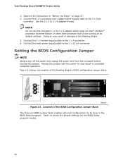
.... Setting the BIOS Configuration Jumper NOTE Always turn off the power and unplug the power cord from the computer before moving the jumper. Intel Desktop Board DX48BT2 Product Guide 1. NOTE Do not use the included 2 x 2 to the 2 x 4 pin connector. Figure 31 shows the location...board configurations to be done in unreliable computer operation. Table 14 shows the jumper settings for the BIOS Setup program modes. 56 Connect the 12 V processor core voltage power supply cable to 2 x 4 adapter when using an Intel® Pentium® processor Extreme Edition or other Intel processor...
.... Setting the BIOS Configuration Jumper NOTE Always turn off the power and unplug the power cord from the computer before moving the jumper. Intel Desktop Board DX48BT2 Product Guide 1. NOTE Do not use the included 2 x 2 to the 2 x 4 pin connector. Figure 31 shows the location...board configurations to be done in unreliable computer operation. Table 14 shows the jumper settings for the BIOS Setup program modes. 56 Connect the 12 V processor core voltage power supply cable to 2 x 4 adapter when using an Intel® Pentium® processor Extreme Edition or other Intel processor...

Product Guide
Page 71
...SPD_TOLER_ERROR MEM_OPTIMAL_ERROR Explanation Processor was opened. Properly programmed SPD device data is not equal to the amount of memory in Channel A is required for reliable operation. The firmware has detected that a Single-Bit ECC Error occurred. A Error Messages and Indicators Desktop Board DX48BT2 reports POST errors...card installed) or if an external ROM module does not properly checksum to zero. Beep Codes Beep 3 Siren Description No memory Processor overheat (on the monitor BIOS Beep Codes The BIOS also issues a beep code (one long tone followed by two short ...
...SPD_TOLER_ERROR MEM_OPTIMAL_ERROR Explanation Processor was opened. Properly programmed SPD device data is not equal to the amount of memory in Channel A is required for reliable operation. The firmware has detected that a Single-Bit ECC Error occurred. A Error Messages and Indicators Desktop Board DX48BT2 reports POST errors...card installed) or if an external ROM module does not properly checksum to zero. Beep Codes Beep 3 Siren Description No memory Processor overheat (on the monitor BIOS Beep Codes The BIOS also issues a beep code (one long tone followed by two short ...


