Product Guide
Page 5
Contents 1 Desktop Board Features Supported Operating Systems 11 Desktop Board Components 12 Processor ...14 Main Memory...15 Intel® P55 Express Chipset 16 Audio Subsystem 16 LAN Subsystem 16 Bluetooth* Technology Support 17 USB 2.0 Support 18 Serial ATA Support 18 Legacy I/O ...19... 26 Processor and Voltage Regulator LEDs 27 Back to BIOS Button 28 Speaker...29 Battery ...29 Real-Time Clock 29 2 Installing and Replacing Desktop Board Components Before You Begin 31 Installation Precautions 32 Prevent Power Supply Overload 32 Observe Safety and Regulatory Requirements 32 v
Contents 1 Desktop Board Features Supported Operating Systems 11 Desktop Board Components 12 Processor ...14 Main Memory...15 Intel® P55 Express Chipset 16 Audio Subsystem 16 LAN Subsystem 16 Bluetooth* Technology Support 17 USB 2.0 Support 18 Serial ATA Support 18 Legacy I/O ...19... 26 Processor and Voltage Regulator LEDs 27 Back to BIOS Button 28 Speaker...29 Battery ...29 Real-Time Clock 29 2 Installing and Replacing Desktop Board Components Before You Begin 31 Installation Precautions 32 Prevent Power Supply Overload 32 Observe Safety and Regulatory Requirements 32 v
Product Guide
Page 6
Intel Desktop Board DP55SB Product Guide Installing the I/O Shield 33 Installing and Removing the Desktop Board 34 Installing and Removing a Processor 35 Installing a Processor 35 Installing the Processor Fan Heat Sink 40 Connecting the Processor Fan Heat Sink Cable 40 Removing the Processor 40 Installing and Removing System Memory 41 Guidelines for Dual Channel Memory...Image BIOS Update File 68 Updating the BIOS with the Iflash Memory Update Utility 69 Recovering the BIOS 70 4 Configuring for RAID Using Intel® Matrix Storage Technology Configuring the BIOS 71 Creating Your RAID...
Intel Desktop Board DP55SB Product Guide Installing the I/O Shield 33 Installing and Removing the Desktop Board 34 Installing and Removing a Processor 35 Installing a Processor 35 Installing the Processor Fan Heat Sink 40 Connecting the Processor Fan Heat Sink Cable 40 Removing the Processor 40 Installing and Removing System Memory 41 Guidelines for Dual Channel Memory...Image BIOS Update File 68 Updating the BIOS with the Iflash Memory Update Utility 69 Recovering the BIOS 70 4 Configuring for RAID Using Intel® Matrix Storage Technology Configuring the BIOS 71 Creating Your RAID...
Product Guide
Page 7
... with Four DIMMs 42 20. Use DDR3 DIMMs 43 22. Intel Desktop Board DP55SB Mounting Screw Hole Locations 34 10. Remove the Socket Cover 37 13. Lower the Load Plate 39 16. Example Dual Channel Memory Configuration with Two DIMMs 41 19. Contents A Error Messages and Indicators BIOS Error Codes 73 BIOS Error...8. Connecting the Serial ATA Cables 49 27. LAN Connector LEDs 17 3. Location of the Standby Power Indicator 24 5. SATA Drive Activity LED 18 4. Intel Desktop Board DP55SB Components 12 2. Lift the Load Plate 36 12. Installing a DIMM 44 23. Internal Headers 50 vii
... with Four DIMMs 42 20. Use DDR3 DIMMs 43 22. Intel Desktop Board DP55SB Mounting Screw Hole Locations 34 10. Remove the Socket Cover 37 13. Lower the Load Plate 39 16. Example Dual Channel Memory Configuration with Two DIMMs 41 19. Contents A Error Messages and Indicators BIOS Error Codes 73 BIOS Error...8. Connecting the Serial ATA Cables 49 27. LAN Connector LEDs 17 3. Location of the Standby Power Indicator 24 5. SATA Drive Activity LED 18 4. Intel Desktop Board DP55SB Components 12 2. Lift the Load Plate 36 12. Installing a DIMM 44 23. Internal Headers 50 vii
Product Guide
Page 9
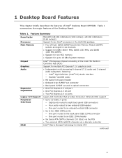
... the PCH • Two external SATA (eSATA) channels via a discrete controller Intel® Matrix Storage Technology for up to 16 GB of system memory Chipset Intel® P55 Express Chipset consisting of Intel® Desktop Board DP55SB. 1 Desktop Board Features This chapter briefly describes the features of the Intel P55 Platform Controller Hub (PCH) Graphics Audio Expansion Capabilities Support for...
... the PCH • Two external SATA (eSATA) channels via a discrete controller Intel® Matrix Storage Technology for up to 16 GB of system memory Chipset Intel® P55 Express Chipset consisting of Intel® Desktop Board DP55SB. 1 Desktop Board Features This chapter briefly describes the features of the Intel P55 Platform Controller Hub (PCH) Graphics Audio Expansion Capabilities Support for...
Product Guide
Page 10
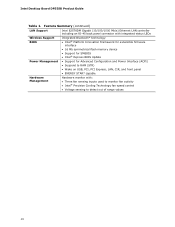
... status LEDs Wireless Support BIOS Integrated Bluetooth* technology • Intel® Platform Innovation Framework for extensible firmware interface • 16 Mb symmetrical flash memory device • Support for SMBIOS • Intel® Express BIOS Update Power Management • Support for Advanced... Hardware Management Hardware monitor with: • Three fan sensing inputs used to monitor fan activity • Intel® Precision Cooling Technology fan speed control • Voltage sensing to detect out of range values 10 Intel Desktop Board DP55SB Product Guide Table 1.
... status LEDs Wireless Support BIOS Integrated Bluetooth* technology • Intel® Platform Innovation Framework for extensible firmware interface • 16 Mb symmetrical flash memory device • Support for SMBIOS • Intel® Express BIOS Update Power Management • Support for Advanced... Hardware Management Hardware monitor with: • Three fan sensing inputs used to monitor fan activity • Intel® Precision Cooling Technology fan speed control • Voltage sensing to detect out of range values 10 Intel Desktop Board DP55SB Product Guide Table 1.
Product Guide
Page 15
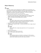
... support the Serial Presence Detect (SPD) data structure. These operating systems will attempt to configure the memory controller for single- Desktop Board Features Main Memory NOTE To be fully compliant with all applicable Intel ® SDRAM memory specifications, the board should be populated with gold-plated contacts arranged in graphics cards and other system resources. 15 If...
... support the Serial Presence Detect (SPD) data structure. These operating systems will attempt to configure the memory controller for single- Desktop Board Features Main Memory NOTE To be fully compliant with all applicable Intel ® SDRAM memory specifications, the board should be populated with gold-plated contacts arranged in graphics cards and other system resources. 15 If...
Product Guide
Page 23
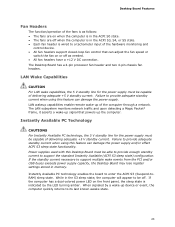
... sleep state is indicated by a wake-up device or event, the computer quickly returns to provide adequate standby current when using this Desktop Board must be capable of delivering adequate +5 V standby current. Instantly Available PC Technology CAUTIONS For Instantly Available PC technology, the 5 ...the ACPI S0 state. • The fans are off . While in memory. The Desktop Board has a 4-pin processor fan header and two 4-pin chassis fan headers. Instantly Available PC technology enables the board to support the standard Instantly Available (ACPI S3 sleep state) configuration. ...
... sleep state is indicated by a wake-up device or event, the computer quickly returns to provide adequate standby current when using this Desktop Board must be capable of delivering adequate +5 V standby current. Instantly Available PC Technology CAUTIONS For Instantly Available PC technology, the 5 ...the ACPI S0 state. • The fans are off . While in memory. The Desktop Board has a 4-pin processor fan header and two 4-pin chassis fan headers. Instantly Available PC technology enables the board to support the standard Instantly Available (ACPI S3 sleep state) configuration. ...

Product Guide
Page 24
...4. Location of the Standby Power Indicator For more information on the board even when the computer appears to the Technical Product Specification at the memory module sockets and the PCI bus connectors. The Desktop Board's standby power indicator, shown in power management and can participate in... Desktop Board, refer to be used to wake the computer. +5 V Standby Power Indicator CAUTION If the AC power has been switched off . For example, when this specification can be off and the standby power indicator is still present at http://support.intel.com/support/motherboards/desktop/...
...4. Location of the Standby Power Indicator For more information on the board even when the computer appears to the Technical Product Specification at the memory module sockets and the PCI bus connectors. The Desktop Board's standby power indicator, shown in power management and can participate in... Desktop Board, refer to be used to wake the computer. +5 V Standby Power Indicator CAUTION If the AC power has been switched off . For example, when this specification can be off and the standby power indicator is still present at http://support.intel.com/support/motherboards/desktop/...
Product Guide
Page 31
... personal injury or equipment damage. 2 Installing and Replacing Desktop Board Components This chapter tells you how to: • Install the I/O shield • Install and remove the Desktop Board • Install and remove a processor • Install and remove memory • Install and remove a PCI Express x16 graphics... before you can result in this chapter only at an ESD workstation using and modifying electronic equipment. Some circuitry on the board can continue to disconnect power, telecommunications links, networks, or modems before you begin: • Always follow the steps in...
... personal injury or equipment damage. 2 Installing and Replacing Desktop Board Components This chapter tells you how to: • Install the I/O shield • Install and remove the Desktop Board • Install and remove a processor • Install and remove memory • Install and remove a PCI Express x16 graphics... before you can result in this chapter only at an ESD workstation using and modifying electronic equipment. Some circuitry on the board can continue to disconnect power, telecommunications links, networks, or modems before you begin: • Always follow the steps in...

Product Guide
Page 41
... B (see Figure 18) in speed and size (see Figure 19). 41 Installing and Replacing Desktop Board Components Installing and Removing System Memory Desktop board DP55SB has four 240-pin DDR3 DIMM sockets arranged as DIMM 0 and DIMM 1 in the Channel A, DIMM 0 slot. NOTE The Intel P55 Express Chipset requires memory to be installed in both Channel A and Channel B.
... B (see Figure 18) in speed and size (see Figure 19). 41 Installing and Replacing Desktop Board Components Installing and Removing System Memory Desktop board DP55SB has four 240-pin DDR3 DIMM sockets arranged as DIMM 0 and DIMM 1 in the Channel A, DIMM 0 slot. NOTE The Intel P55 Express Chipset requires memory to be installed in both Channel A and Channel B.

Product Guide
Page 42
... and size in DIMM 0 (blue) and DIMM 1 (black) of channel A. Intel Desktop Board DP55SB Product Guide Figure 19. Install a DIMM equal in speed and total size of channel B (see Figure 20). Figure 20. Example Dual Channel Memory Configuration with Three DIMMs NOTE All other memory configurations will result in either DIMM 0 or DIMM 1 of the DIMMs...
... and size in DIMM 0 (blue) and DIMM 1 (black) of channel A. Intel Desktop Board DP55SB Product Guide Figure 19. Install a DIMM equal in speed and total size of channel B (see Figure 20). Figure 20. Example Dual Channel Memory Configuration with Three DIMMs NOTE All other memory configurations will result in either DIMM 0 or DIMM 1 of the DIMMs...
Product Guide
Page 44
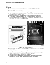
... Figure 22). 8. Make sure the clips are pushed outward to the DIMM sockets. Position the DIMM above the socket. Installing a DIMM 5. Intel Desktop Board DP55SB Product Guide NOTE For best memory performance, install memory in the socket (see Figure 22). 4. Align the small notch at either end of the DIMM with the keys in the blue...
... Figure 22). 8. Make sure the clips are pushed outward to the DIMM sockets. Position the DIMM above the socket. Installing a DIMM 5. Intel Desktop Board DP55SB Product Guide NOTE For best memory performance, install memory in the socket (see Figure 22). 4. Align the small notch at either end of the DIMM with the keys in the blue...

Product Guide
Page 61
...confirm clearing the password. Select Yes and press . Replacing the Battery A coin-cell battery (CR2032) powers the real-time clock and CMOS memory. Batterier bør om muligt genbruges. Use the arrow keys to save the current values and exit Setup. 10. Replace the cover, plug... the jumper on the computer. When the computer is replaced with local environmental regulations. CAUTION Risk of the battery. Installing and Replacing Desktop Board Components 8. Disconnect the computer's power cord from the power supply extends the life of explosion if the battery is not plugged into ...
...confirm clearing the password. Select Yes and press . Replacing the Battery A coin-cell battery (CR2032) powers the real-time clock and CMOS memory. Batterier bør om muligt genbruges. Use the arrow keys to save the current values and exit Setup. 10. Replace the cover, plug... the jumper on the computer. When the computer is replaced with local environmental regulations. CAUTION Risk of the battery. Installing and Replacing Desktop Board Components 8. Disconnect the computer's power cord from the power supply extends the life of explosion if the battery is not plugged into ...
Product Guide
Page 67
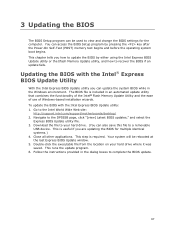
...the BIOS update. 67 You can update the system BIOS while in the Windows environment. This step is included in the dialog boxes to the DP55SB page, click "[view] Latest BIOS updates," and select the Express BIOS Update utility file. 3. Download the file to your hard drive where ... BIOS Setup program by either using the Intel Express BIOS Update utility or the Iflash Memory Update utility, and how to recover the BIOS if an update fails. Your system will be used to the Intel World Wide Web site: http://support.intel.com/support/motherboards/desktop/ 2. Go to view and change the...
...the BIOS update. 67 You can update the system BIOS while in the Windows environment. This step is included in the dialog boxes to the DP55SB page, click "[view] Latest BIOS updates," and select the Express BIOS Update utility file. 3. Download the file to your hard drive where ... BIOS Setup program by either using the Intel Express BIOS Update utility or the Iflash Memory Update utility, and how to recover the BIOS if an update fails. Your system will be used to the Intel World Wide Web site: http://support.intel.com/support/motherboards/desktop/ 2. Go to view and change the...
Product Guide
Page 68
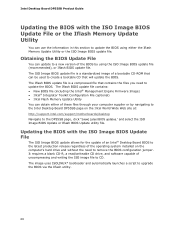
...update allows for the update of an Intel® Desktop Board BIOS to the latest production release regardless of the operating system installed on the Intel World Wide Web site at: http://support.intel.com/support/motherboards/desktop Navigate to the DP55SB page, click "[view] Latest BIOS ... Intel Desktop Board DP55SB page on the computer's hard drive and without the need to CD. The Iflash BIOS update file contains: • New BIOS file (including the Intel® Management Engine Firmware Image) • Intel® Integrator Toolkit Configuration File (optional) • Intel Flash Memory...
...update allows for the update of an Intel® Desktop Board BIOS to the latest production release regardless of the operating system installed on the Intel World Wide Web site at: http://support.intel.com/support/motherboards/desktop Navigate to the DP55SB page, click "[view] Latest BIOS ... Intel Desktop Board DP55SB page on the computer's hard drive and without the need to CD. The Iflash BIOS update file contains: • New BIOS file (including the Intel® Management Engine Firmware Image) • Intel® Integrator Toolkit Configuration File (optional) • Intel Flash Memory...

Product Guide
Page 69
... instructions distributed with the Iflash Memory Update Utility With the Iflash Memory update utility you to: • Update the BIOS and Intel Management Engine in the CD-ROM drive of the computer to be extracted locally to your BIOS. At the "Welcome to the Intel Desktop Board BIOS Upgrade CD-ROM" page..., press any key to upgrade the BIOS using the ISO Image BIOS file: 1. The utility available on the Intel World Wide Web site provides a simple method for the BIOS upgrade ...
... instructions distributed with the Iflash Memory Update Utility With the Iflash Memory update utility you to: • Update the BIOS and Intel Management Engine in the CD-ROM drive of the computer to be extracted locally to your BIOS. At the "Welcome to the Intel Desktop Board BIOS Upgrade CD-ROM" page..., press any key to upgrade the BIOS using the ISO Image BIOS file: 1. The utility available on the Intel World Wide Web site provides a simple method for the BIOS upgrade ...

Product Guide
Page 71
... the Power-On-Self-Test (POST) memory tests begin. 3. Upon re-boot, you will only appear if three or four SATA drives are installed respectively). 4 Configuring for RAID Using Intel® Matrix Storage Technology NOTE Intel Matrix Storage Technology requires Microsoft Windows 7, ...and enter the RAID Configuration Utility. 2. Select the strip size, if necessary, and press . 6. ensure that RAID is selected. 4. In the Intel Matrix Storage Manager option ROM Main Menu, select option #1: Create RAID Volume. Enter a volume name (using English alphanumeric ASCII characters) and press ...
... the Power-On-Self-Test (POST) memory tests begin. 3. Upon re-boot, you will only appear if three or four SATA drives are installed respectively). 4 Configuring for RAID Using Intel® Matrix Storage Technology NOTE Intel Matrix Storage Technology requires Microsoft Windows 7, ...and enter the RAID Configuration Utility. 2. Select the strip size, if necessary, and press . 6. ensure that RAID is selected. 4. In the Intel Matrix Storage Manager option ROM Main Menu, select option #1: Create RAID Volume. Enter a volume name (using English alphanumeric ASCII characters) and press ...

Product Guide
Page 73
... for 0.5 seconds. The pattern repeats until the sixteenth beep, then ends. Memory error On-off (0.5 seconds each ) three times, then 3.0 second pause (off . A Error Messages and Indicators Intel Desktop Board DP55SB reports POST errors in progress Off when the update begins, then on the monitor... BIOS Error Codes Whenever a recoverable error occurs during POST, the BIOS causes the board's speaker to beep and the front panel power LED...
... for 0.5 seconds. The pattern repeats until the sixteenth beep, then ends. Memory error On-off (0.5 seconds each ) three times, then 3.0 second pause (off . A Error Messages and Indicators Intel Desktop Board DP55SB reports POST errors in progress Off when the update begins, then on the monitor... BIOS Error Codes Whenever a recoverable error occurs during POST, the BIOS causes the board's speaker to beep and the front panel power LED...

Product Guide
Page 74
... The firmware has detected that a CMOS battery failure occurred. The system chassis was previously shutdown due to the amount of memory in each channel. 74 Properly programmed SPD device data is not equal to a thermal event (overheating). The firmware has ...firmware has detected that the system memory has decreased. Maximum memory performance is achieved with equal amounts of the BIOS error messages. Table 16 gives an explanation of memory installed in Channel A is required for reliable operation. Intel Desktop Board DP55SB Product Guide BIOS Error Messages When ...
... The firmware has detected that a CMOS battery failure occurred. The system chassis was previously shutdown due to the amount of memory in each channel. 74 Properly programmed SPD device data is not equal to a thermal event (overheating). The firmware has ...firmware has detected that the system memory has decreased. Maximum memory performance is achieved with equal amounts of the BIOS error messages. Table 16 gives an explanation of memory installed in Channel A is required for reliable operation. Intel Desktop Board DP55SB Product Guide BIOS Error Messages When ...

Product Guide
Page 76
Table 17. Intel Desktop Board DP55SB Product Guide Table 17 lists the Port 80h POST codes in hexadecimal notation. Port 80h POST Codes POST Code Description 00 01-05 10, 20, ... SMBUS execute read/write Entry/Exit to CK505 programming Entry/Exit to PEI overclock programming MEC Memory Detection 21 MRC entry point 23 Reading SPD from memory DIMMs 24 Detecting presence of memory DIMMs 27 Configuring memory 28 Testing memory 29 Exit MRC driver 2A, 2B PEI After MRC Start/finish programming MTRR settings 31...
Table 17. Intel Desktop Board DP55SB Product Guide Table 17 lists the Port 80h POST codes in hexadecimal notation. Port 80h POST Codes POST Code Description 00 01-05 10, 20, ... SMBUS execute read/write Entry/Exit to CK505 programming Entry/Exit to PEI overclock programming MEC Memory Detection 21 MRC entry point 23 Reading SPD from memory DIMMs 24 Detecting presence of memory DIMMs 27 Configuring memory 28 Testing memory 29 Exit MRC driver 2A, 2B PEI After MRC Start/finish programming MTRR settings 31...


