Product Guide
Page 5
Contents 1 Desktop Board Features Supported Operating Systems 11 Desktop Board Components 12 Processor ...14 Main Memory...15 Intel® P55 Express Chipset 16 Audio Subsystem 16 LAN Subsystem 16 Bluetooth* Technology Support 17 USB 2.0 Support 17 Serial ATA Support 18 Legacy I/O ...19 Expandability...19 BIOS ...20 Serial ATA ... 27 Back to BIOS Button 28 Speaker...29 Battery ...29 Real-Time Clock 29 2 Installing and Replacing Desktop Board Components Before You Begin 31 Installation Precautions 32 Prevent Power Supply Overload 32 Observe Safety and Regulatory Requirements 32 v
Contents 1 Desktop Board Features Supported Operating Systems 11 Desktop Board Components 12 Processor ...14 Main Memory...15 Intel® P55 Express Chipset 16 Audio Subsystem 16 LAN Subsystem 16 Bluetooth* Technology Support 17 USB 2.0 Support 17 Serial ATA Support 18 Legacy I/O ...19 Expandability...19 BIOS ...20 Serial ATA ... 27 Back to BIOS Button 28 Speaker...29 Battery ...29 Real-Time Clock 29 2 Installing and Replacing Desktop Board Components Before You Begin 31 Installation Precautions 32 Prevent Power Supply Overload 32 Observe Safety and Regulatory Requirements 32 v
Product Guide
Page 6
Intel Desktop Board DP55KG Product Guide Installing the I/O Shield 33 Installing and Removing the Desktop Board 34 Installing and Removing a Processor 35 Installing a Processor 35 Installing the Processor Fan Heat Sink 40 Connecting the Processor Fan Heat Sink Cable 40 Removing... the Audio System 55 Connecting Chassis Fan and Power Supply Cables 56 Connecting Chassis Fan Cables 56 Connecting Power Supply Cables 57 Connecting the Bluetooth Antenna 58 Setting the BIOS Configuration Jumper 59 Clearing Passwords 60 Replacing the Battery 61 3 Updating the BIOS Updating the BIOS with the...
Intel Desktop Board DP55KG Product Guide Installing the I/O Shield 33 Installing and Removing the Desktop Board 34 Installing and Removing a Processor 35 Installing a Processor 35 Installing the Processor Fan Heat Sink 40 Connecting the Processor Fan Heat Sink Cable 40 Removing... the Audio System 55 Connecting Chassis Fan and Power Supply Cables 56 Connecting Chassis Fan Cables 56 Connecting Power Supply Cables 57 Connecting the Bluetooth Antenna 58 Setting the BIOS Configuration Jumper 59 Clearing Passwords 60 Replacing the Battery 61 3 Updating the BIOS Updating the BIOS with the...
Product Guide
Page 8
...73 16. Location of the BIOS Configuration Jumper Block 59 33. Connecting the Bluetooth Antenna 58 32. BIOS Beep Codes 73 15. Port 80h POST Codes 76 18. EMC Regulations 88 22. Intel Desktop Board DP55KG Product Guide 28. Feature Summary 9 2. Front Panel CIR Receiver (Input) ... Signal Names 53 11. Lead-Free Second Level Interconnect Marks 85 20. China RoHS Environmentally Friendly Use Period Mark 86 21. Intel Desktop Board DP55KG China RoHS Material Self Declaration Table 87 Tables 1. LAN Connector LEDs 17 4. IEEE 1394a Header Signal Names 54 12. Removing ...
...73 16. Location of the BIOS Configuration Jumper Block 59 33. Connecting the Bluetooth Antenna 58 32. BIOS Beep Codes 73 15. Port 80h POST Codes 76 18. EMC Regulations 88 22. Intel Desktop Board DP55KG Product Guide 28. Feature Summary 9 2. Front Panel CIR Receiver (Input) ... Signal Names 53 11. Lead-Free Second Level Interconnect Marks 85 20. China RoHS Environmentally Friendly Use Period Mark 86 21. Intel Desktop Board DP55KG China RoHS Material Self Declaration Table 87 Tables 1. LAN Connector LEDs 17 4. IEEE 1394a Header Signal Names 54 12. Removing ...
Product Guide
Page 10
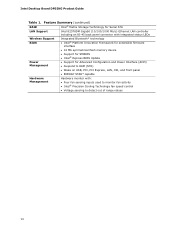
Intel Desktop Board DP55KG Product Guide Table 1. Feature Summary (continued) RAID Intel® Matrix Storage Technology for Serial ATA LAN Support Intel 82578DM Gigabit (10/100/1000 Mb/s) Ethernet LAN controller including an RJ-45 back panel connector with integrated status LEDs Wireless Support BIOS Integrated Bluetooth* technology • Intel® Platform Innovation Framework for extensible firmware interface •...
Intel Desktop Board DP55KG Product Guide Table 1. Feature Summary (continued) RAID Intel® Matrix Storage Technology for Serial ATA LAN Support Intel 82578DM Gigabit (10/100/1000 Mb/s) Ethernet LAN controller including an RJ-45 back panel connector with integrated status LEDs Wireless Support BIOS Integrated Bluetooth* technology • Intel® Platform Innovation Framework for extensible firmware interface •...
Product Guide
Page 13
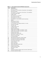
... chassis fan header USB 2.0 headers IEEE 1394a header BIOS configuration jumper block Serial ATA connectors Chassis intrusion header BlueTooth* module Speaker Auxiliary PCI Express graphics power connector (SATA-style) Auxiliary chassis fan header 13 Intel Desktop Board DP55KG Components Label A B C D E F G H I J K L M N O P Q R S T U V W X Y Z AA BB CC DD EE FF GG HH II JJ KK LL MM Description PCI...
... chassis fan header USB 2.0 headers IEEE 1394a header BIOS configuration jumper block Serial ATA connectors Chassis intrusion header BlueTooth* module Speaker Auxiliary PCI Express graphics power connector (SATA-style) Auxiliary chassis fan header 13 Intel Desktop Board DP55KG Components Label A B C D E F G H I J K L M N O P Q R S T U V W X Y Z AA BB CC DD EE FF GG HH II JJ KK LL MM Description PCI...
Product Guide
Page 17
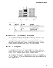
...LEDs Table 3. Driver support is occurring 10 Mb/s data rate 100 Mb/s data rate 1000 Mb/s data rate Bluetooth* Technology Support The Desktop Board includes an integrated Bluetooth* module (Figure 1, JJ). USB 2.0 support requires both an operating system and drivers that do not support USB ...normally at USB 1.1 speeds. USB 2.0 ports are backward compatible with a variety of Bluetooth-enabled devices. This may be required to an onboard vertical connector). USB 2.0 Support The Desktop Board provides 13 USB 2.0 ports (eight ports routed to back panel connectors, four ports ...
...LEDs Table 3. Driver support is occurring 10 Mb/s data rate 100 Mb/s data rate 1000 Mb/s data rate Bluetooth* Technology Support The Desktop Board includes an integrated Bluetooth* module (Figure 1, JJ). USB 2.0 support requires both an operating system and drivers that do not support USB ...normally at USB 1.1 speeds. USB 2.0 ports are backward compatible with a variety of Bluetooth-enabled devices. This may be required to an onboard vertical connector). USB 2.0 Support The Desktop Board provides 13 USB 2.0 ports (eight ports routed to back panel connectors, four ports ...
Product Guide
Page 31
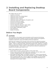
...the Desktop Board • Install and remove a processor • Install and remove memory • Install and remove a PCI Express x16 graphics card • Connect the Serial ATA cables • Connect to the internal headers • Connect to the audio system • Connect chassis fan and power supply cables • Connect the Bluetooth ... of the procedures described in the correct order. • Set up a log to a metal part of the computer chassis. 31 Some circuitry on the board can damage components. Perform the procedures described in personal injury or equipment damage.
...the Desktop Board • Install and remove a processor • Install and remove memory • Install and remove a PCI Express x16 graphics card • Connect the Serial ATA cables • Connect to the internal headers • Connect to the audio system • Connect chassis fan and power supply cables • Connect the Bluetooth ... of the procedures described in the correct order. • Set up a log to a metal part of the computer chassis. 31 Some circuitry on the board can damage components. Perform the procedures described in personal injury or equipment damage.
Product Guide
Page 58
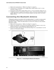
Intel Desktop Board DP55KG Product Guide 1. Observe the precautions in "Before You Begin" on page 31. 2. In order to communicate with the desktop board. Observe the precautions in "Before You Begin" on page 31. 2. Remove the paper backing from the antenna (Figure 31,...wire (Figure 31, B) to the 2 x 4 pin connector (Figure 30, A). 3. Attach the connector on the Bluetooth module (Figure 31, A). 3. If additional power is provided with Bluetooth-enabled devices, you must connect the antenna to the SATA-style PCI Express graphics auxiliary power connector (Figure 30, B). ...
Intel Desktop Board DP55KG Product Guide 1. Observe the precautions in "Before You Begin" on page 31. 2. In order to communicate with the desktop board. Observe the precautions in "Before You Begin" on page 31. 2. Remove the paper backing from the antenna (Figure 31,...wire (Figure 31, B) to the 2 x 4 pin connector (Figure 30, A). 3. Attach the connector on the Bluetooth module (Figure 31, A). 3. If additional power is provided with Bluetooth-enabled devices, you must connect the antenna to the SATA-style PCI Express graphics auxiliary power connector (Figure 30, B). ...