
Product Guide
Page 5
Contents 1 Desktop Board Features Supported Operating Systems 11 Desktop Board Components 12 Processor ...14 Intel® H61 Express Chipset 15 Main Memory...15 Graphics Subsystem 16 Integrated Graphics 16 Analog Display (VGA 16 PCI Express* x16 ...Support 21 Onboard Speaker 25 Real-Time Clock Subsystem 25 2 Installing and Replacing Desktop Board Components Before You Begin 27 Installation Precautions 28 Prevent Power Supply Overload 28 Observe Safety and Regulatory Requirements 28 Installing the I/O Shield 29 Installing and Removing the Desktop Board 30 Installing and Removing a ...
Contents 1 Desktop Board Features Supported Operating Systems 11 Desktop Board Components 12 Processor ...14 Intel® H61 Express Chipset 15 Main Memory...15 Graphics Subsystem 16 Integrated Graphics 16 Analog Display (VGA 16 PCI Express* x16 ...Support 21 Onboard Speaker 25 Real-Time Clock Subsystem 25 2 Installing and Replacing Desktop Board Components Before You Begin 27 Installation Precautions 28 Prevent Power Supply Overload 28 Observe Safety and Regulatory Requirements 28 Installing the I/O Shield 29 Installing and Removing the Desktop Board 30 Installing and Removing a ...
Product Guide
Page 6
...Intel Desktop Board DH61WW Product Guide Connecting to the Internal Headers 43 Front Panel Audio Header 44 S/PDIF Header 44 Chassis Intrusion Header 45 TPM Header 45 Front Panel Header 46 Serial Header 46 Front Panel USB 2.0 Header 47 Connecting to the Audio System 48 Connecting Chassis Fan and Power Supply...Connecting a Chassis Fan Cable 49 Connecting Power Supply Cables 50 Setting the BIOS Configuration Jumper 51 Clearing Passwords in the BIOS Setup Program 52 Replacing the Battery 53 3 Updating the BIOS Updating the BIOS with the Intel® Express BIOS Update Utility 59 ...
...Intel Desktop Board DH61WW Product Guide Connecting to the Internal Headers 43 Front Panel Audio Header 44 S/PDIF Header 44 Chassis Intrusion Header 45 TPM Header 45 Front Panel Header 46 Serial Header 46 Front Panel USB 2.0 Header 47 Connecting to the Audio System 48 Connecting Chassis Fan and Power Supply...Connecting a Chassis Fan Cable 49 Connecting Power Supply Cables 50 Setting the BIOS Configuration Jumper 51 Clearing Passwords in the BIOS Setup Program 52 Replacing the Battery 53 3 Updating the BIOS Updating the BIOS with the Intel® Express BIOS Update Utility 59 ...

Product Guide
Page 7
...14. Location of the BIOS Configuration Jumper Block 51 23. Location of the Chassis Fan Header 49 21. Location of the Standby Power Indicator 23 4. Remove the Processor from the Protective Cover 33 9. Removing a PCI Express x16 Graphics Card 41 17. Installing ... a Serial ATA Cable 42 18. Install the Processor 33 10. Connecting Power Supply Cables 50 22. Installing a PCI Express x16 Graphics Card 40 16. Intel Desktop Board DH61WW Components 12 2. Intel Desktop Board DH61WW China RoHS Material Self Declaration Table 72 vii Removing the Battery 58 24...
...14. Location of the BIOS Configuration Jumper Block 51 23. Location of the Chassis Fan Header 49 21. Location of the Standby Power Indicator 23 4. Remove the Processor from the Protective Cover 33 9. Removing a PCI Express x16 Graphics Card 41 17. Installing ... a Serial ATA Cable 42 18. Install the Processor 33 10. Connecting Power Supply Cables 50 22. Installing a PCI Express x16 Graphics Card 40 16. Intel Desktop Board DH61WW Components 12 2. Intel Desktop Board DH61WW China RoHS Material Self Declaration Table 72 vii Removing the Battery 58 24...
Product Guide
Page 10
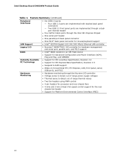
...; One parallel port back panel connector • One PS/2* back panel connector for mouse/keyboard support • Intel® 82579V Gigabit (10/100/1000 Mb/s) Ethernet LAN controller Legacy I/O BIOS • Nuvoton* W83677HG-i I/O... Monitoring • Hardware monitoring through the Nuvoton I/O controller • Voltage sense to detect out of range power supply voltages • Thermal sense to detect out of range thermal values • Two fan headers using PWM control...; Support for Platform Environmental Control Interface (PECI) 10 Intel Desktop Board DH61WW Product Guide Table 1.
...; One parallel port back panel connector • One PS/2* back panel connector for mouse/keyboard support • Intel® 82579V Gigabit (10/100/1000 Mb/s) Ethernet LAN controller Legacy I/O BIOS • Nuvoton* W83677HG-i I/O... Monitoring • Hardware monitoring through the Nuvoton I/O controller • Voltage sense to detect out of range power supply voltages • Thermal sense to detect out of range thermal values • Two fan headers using PWM control...; Support for Platform Environmental Control Interface (PECI) 10 Intel Desktop Board DH61WW Product Guide Table 1.

Product Guide
Page 14
... must be purchased separately. For information on Intel Desktop Board DH61WW consult the following online resources: • Intel Desktop Board DH61WW • Desktop Board Support • Available configurations for Intel Desktop Board DH61WW, go /buildit Processor CAUTION Failure to use an appropriate power supply and/or not connecting the 12 V (2 x 2 pin) power connector to the Desktop Board may not...
... must be purchased separately. For information on Intel Desktop Board DH61WW consult the following online resources: • Intel Desktop Board DH61WW • Desktop Board Support • Available configurations for Intel Desktop Board DH61WW, go /buildit Processor CAUTION Failure to use an appropriate power supply and/or not connecting the 12 V (2 x 2 pin) power connector to the Desktop Board may not...

Product Guide
Page 21
... system control. The LAN subsystem monitors network traffic and upon detecting a Magic Packet* frame, it was in before power was interrupted (either on page 50 for the power supply must be set by Pulse Width Modulation. • The rear chassis fan header supports Linear Fan Control on when...with 4-wire and 3-wire chassis fans. LAN wakeup capabilities enable remote wake-up the computer. 21 Desktop Board Features Hardware Support Power Connectors ATX12V-compliant power supplies can adjust the fan speed or switch the fan on or off as follows: • The fans are off when the ...
... system control. The LAN subsystem monitors network traffic and upon detecting a Magic Packet* frame, it was in before power was interrupted (either on page 50 for the power supply must be set by Pulse Width Modulation. • The rear chassis fan header supports Linear Fan Control on when...with 4-wire and 3-wire chassis fans. LAN wakeup capabilities enable remote wake-up the computer. 21 Desktop Board Features Hardware Support Power Connectors ATX12V-compliant power supplies can adjust the fan speed or switch the fan on or off as follows: • The fans are off when the ...

Product Guide
Page 22
... sleep state functionality. The use of delivering adequate +5 V standby current. Failure to wake the computer. Intel Desktop Board DH61WW Product Guide Instantly Available PC Technology CAUTION For Instantly Available PC technology, the 5 V standby line for the power supply must be capable of Instantly Available PC technology requires operating system support and PCI 2.2 compliant add...
... sleep state functionality. The use of delivering adequate +5 V standby current. Failure to wake the computer. Intel Desktop Board DH61WW Product Guide Instantly Available PC Technology CAUTION For Instantly Available PC technology, the 5 V standby line for the power supply must be capable of Instantly Available PC technology requires operating system support and PCI 2.2 compliant add...
Product Guide
Page 25
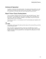
... POST. When the computer is not plugged into a wall socket, the battery has an estimated life of three years. Replace the battery with standby power applied by the power supply. When the computer is plugged in CMOS RAM (for a description of the battery. When the battery voltage drops below a certain level, the BIOS...
... POST. When the computer is not plugged into a wall socket, the battery has an estimated life of three years. Replace the battery with standby power applied by the power supply. When the computer is plugged in CMOS RAM (for a description of the battery. When the battery voltage drops below a certain level, the BIOS...
Product Guide
Page 27
... the procedures described in this chapter. Some circuitry on the board can continue to the audio system • Connect chassis fan and power supply cables • Set the BIOS configuration jumper • Clear passwords • Replace the battery Before You Begin CAUTIONS The procedures in... foam pad. Follow these guidelines before performing any procedures can result in personal injury or equipment damage. Disconnect the computer from its power source and from any telecommunications links, networks, or modems before you open the computer or perform any of the computer chassis. 27...
... the procedures described in this chapter. Some circuitry on the board can continue to the audio system • Connect chassis fan and power supply cables • Set the BIOS configuration jumper • Clear passwords • Replace the battery Before You Begin CAUTIONS The procedures in... foam pad. Follow these guidelines before performing any procedures can result in personal injury or equipment damage. Disconnect the computer from its power source and from any telecommunications links, networks, or modems before you open the computer or perform any of the computer chassis. 27...
Product Guide
Page 28
... increase your computer meets safety and regulatory requirements. If the instructions for desktop board power consumption. To avoid injury, be careful of the power supplies output circuits plus enough headroom for the chassis are inconsistent with the chassis and associated modules. Intel Desktop Board DH61WW Product Guide Installation Precautions When you install and test the...
... increase your computer meets safety and regulatory requirements. If the instructions for desktop board power consumption. To avoid injury, be careful of the power supplies output circuits plus enough headroom for the chassis are inconsistent with the chassis and associated modules. Intel Desktop Board DH61WW Product Guide Installation Precautions When you install and test the...

Product Guide
Page 39
... the system. Observe the precautions in the PCI Express x16 connector, remove the card to gain access to the DIMMs. 6. Remove the AC power cord from the socket, and store it in the upright position (closed); Hold the DIMM by the PCI Express card during installation. Installing and...installing a PCI Express x16 graphics card, make sure that the card is installed in "Before You Begin" on the over-current protection of the power supply, certain Desktop Board components and/or traces may result across the connector pins. Gently spread the retaining clips at each end of the socket. 7....
... the system. Observe the precautions in the PCI Express x16 connector, remove the card to gain access to the DIMMs. 6. Remove the AC power cord from the socket, and store it in the upright position (closed); Hold the DIMM by the PCI Express card during installation. Installing and...installing a PCI Express x16 graphics card, make sure that the card is installed in "Before You Begin" on the over-current protection of the power supply, certain Desktop Board components and/or traces may result across the connector pins. Gently spread the retaining clips at each end of the socket. 7....

Product Guide
Page 49
Figure 20 shows the location of the Chassis Fan Header 49 Installing and Replacing Desktop Board Components Connecting Chassis Fan and Power Supply Cables Connecting a Chassis Fan Cable Connect chassis fan cables to the chassis fan header on the Desktop Board. Location of the chassis fan header. Figure 20.
Figure 20 shows the location of the Chassis Fan Header 49 Installing and Replacing Desktop Board Components Connecting Chassis Fan and Power Supply Cables Connecting a Chassis Fan Cable Connect chassis fan cables to the chassis fan header on the Desktop Board. Location of the chassis fan header. Figure 20.

Product Guide
Page 50
... in damage to the 2 x 2 pin connector (Figure 21, A). 3. Figure 21 shows the location of the power connectors. Intel Desktop Board DH61WW Product Guide Connecting Power Supply Cables CAUTION Failure to use an appropriate power supply and/or not connecting the 12 V power connector (Figure 21, A) to the Desktop Board may result in "Before You Begin" on page 27. 2.
... in damage to the 2 x 2 pin connector (Figure 21, A). 3. Figure 21 shows the location of the power connectors. Intel Desktop Board DH61WW Product Guide Connecting Power Supply Cables CAUTION Failure to use an appropriate power supply and/or not connecting the 12 V power connector (Figure 21, A) to the Desktop Board may result in "Before You Begin" on page 27. 2.

Product Guide
Page 53
...the current values and exit Setup. 10. Disconnect the computer's power cord from the power supply extends the life of explosion if the battery is plugged in... CMOS RAM (for example, the date and time) might not be recycled where possible. Remove the computer cover. 12. Replacing the Battery A coin-cell battery (CR2032) powers... a certain level, the BIOS Setup program settings stored in , the standby current from the AC power source. 11. PRÉCAUTION Risque d'explosion si la pile usagée est remplacée ...
...the current values and exit Setup. 10. Disconnect the computer's power cord from the power supply extends the life of explosion if the battery is plugged in... CMOS RAM (for example, the date and time) might not be recycled where possible. Remove the computer cover. 12. Replacing the Battery A coin-cell battery (CR2032) powers... a certain level, the BIOS Setup program settings stored in , the standby current from the AC power source. 11. PRÉCAUTION Risque d'explosion si la pile usagée est remplacée ...

Product Guide
Page 75
... other modules or peripherals, as applicable, are marked accordingly. Regulatory Compliance Korea Class B Statement Korea Class B Statement translation: This equipment is for the host chassis, power supply, and other modules: • Product certifications or lack of certifications • External I/O cable shielding and filtering • Mounting, grounding, and bonding requirements • Keying ... peripherals, as applicable, have passed Class B EMC testing and are not Class B EMC compliant before integration, then EMC testing may be hazardous If the power supply and other areas.
... other modules or peripherals, as applicable, are marked accordingly. Regulatory Compliance Korea Class B Statement Korea Class B Statement translation: This equipment is for the host chassis, power supply, and other modules: • Product certifications or lack of certifications • External I/O cable shielding and filtering • Mounting, grounding, and bonding requirements • Keying ... peripherals, as applicable, have passed Class B EMC testing and are not Class B EMC compliant before integration, then EMC testing may be hazardous If the power supply and other areas.

Product Guide
Page 77
...intel.com/go to the European EMC directive, Low Voltage directive (as applicable), and ROHS directive, should be UL listed or recognized and suitable for the country or market where used. In the United States A certification mark by a Nationally Recognized Testing Laboratory (NRTL) such as the power supply...requirements. If the chassis and other directives, such as CSA or cUL signifies compliance with all applicable European requirements. Intel has worked directly with Canadian EMC regulations. Agency certification marks on product features. The FCC Class B logo for ...
...intel.com/go to the European EMC directive, Low Voltage directive (as applicable), and ROHS directive, should be UL listed or recognized and suitable for the country or market where used. In the United States A certification mark by a Nationally Recognized Testing Laboratory (NRTL) such as the power supply...requirements. If the chassis and other directives, such as CSA or cUL signifies compliance with all applicable European requirements. Intel has worked directly with Canadian EMC regulations. Agency certification marks on product features. The FCC Class B logo for ...

DH61WW Technical Product Specification
Page 8
Intel Desktop Board DH61WW Technical Product Specification 1.16 Power Management 31 1.16.1 ACPI 31 1.16.2 Hardware Support 34 2 Technical Reference 2.1 Memory Resources 38 2.1.1 Addressable Memory 38 2.1.2 ... 41 2.2.2 Component-side Connectors and Headers 42 2.3 BIOS Configuration Jumper Block 51 2.4 Mechanical Considerations 53 2.4.1 Form Factor 53 2.5 Electrical Considerations 54 2.5.1 Power Supply Considerations 54 2.5.2 Fan Header Current Capability 55 2.5.3 Add-in Board Considerations 55 2.6 Thermal Considerations 56 2.7 Reliability 58 2.8 Environmental 58 3 Overview of...
Intel Desktop Board DH61WW Technical Product Specification 1.16 Power Management 31 1.16.1 ACPI 31 1.16.2 Hardware Support 34 2 Technical Reference 2.1 Memory Resources 38 2.1.1 Addressable Memory 38 2.1.2 ... 41 2.2.2 Component-side Connectors and Headers 42 2.3 BIOS Configuration Jumper Block 51 2.4 Mechanical Considerations 53 2.4.1 Form Factor 53 2.5 Electrical Considerations 54 2.5.1 Power Supply Considerations 54 2.5.2 Fan Header Current Capability 55 2.5.3 Add-in Board Considerations 55 2.6 Thermal Considerations 56 2.7 Reliability 58 2.8 Environmental 58 3 Overview of...

DH61WW Technical Product Specification
Page 10
Front Panel Header 48 23. Recommended Power Supply Current Values 54 27. BIOS Beep Codes 65 35. Regulatory Compliance Marks 81 x Main Power Connector 47 22. BIOS Setup Configuration Jumper Settings 52 26. Port 80h POST Codes 68 39. States for Components 57 29...Keys 60 32. BIOS Error Messages 66 37. Typical Port 80h POST Sequence 72 40. Intel Desktop Board DH61WW Technical Product Specification 21. LPC Debug Header 50 25. Thermal Considerations for a One-Color Power LED 49 24. Environmental Specifications 58 30. BIOS Setup Program Menu Bar 60 31. ...
Front Panel Header 48 23. Recommended Power Supply Current Values 54 27. BIOS Beep Codes 65 35. Regulatory Compliance Marks 81 x Main Power Connector 47 22. BIOS Setup Configuration Jumper Settings 52 26. Port 80h POST Codes 68 39. States for Components 57 29...Keys 60 32. BIOS Error Messages 66 37. Typical Port 80h POST Sequence 72 40. Intel Desktop Board DH61WW Technical Product Specification 21. LPC Debug Header 50 25. Thermal Considerations for a One-Color Power LED 49 24. Environmental Specifications 58 30. BIOS Setup Program Menu Bar 60 31. ...

DH61WW Technical Product Specification
Page 12
... the Intel® 82579V Gigabit Ethernet Controller • One PCI Express 2.0 x16 add-in card connector • One PCI Express 2.0 x1 add-in card connector • One Conventional PCI bus connector Hardware Monitor Subsystem • Hardware monitoring through the Nuvoton Super I/O controller • Voltage sense to detect out of range power supply voltages...
... the Intel® 82579V Gigabit Ethernet Controller • One PCI Express 2.0 x16 add-in card connector • One PCI Express 2.0 x1 add-in card connector • One Conventional PCI bus connector Hardware Monitor Subsystem • Hardware monitoring through the Nuvoton Super I/O controller • Voltage sense to detect out of range power supply voltages...

DH61WW Technical Product Specification
Page 16
... above. Refer to : http://processormatch.intel.com CAUTION Use only the processors listed on power supply requirements for the most up-to support the Intel Core i7, Intel Core i5, Intel Core i3, and Intel Pentium processors in the future. Other processors may be supported in an LGA1155 socket. Intel Desktop Board DH61WW Technical Product Specification 1.2 Legacy Considerations This...
... above. Refer to : http://processormatch.intel.com CAUTION Use only the processors listed on power supply requirements for the most up-to support the Intel Core i7, Intel Core i5, Intel Core i3, and Intel Pentium processors in the future. Other processors may be supported in an LGA1155 socket. Intel Desktop Board DH61WW Technical Product Specification 1.2 Legacy Considerations This...


