

Product Specification
Page 7
... 11. Front Panel USB Headers 44 19. Back Panel Audio Connectors 22 5. Audio Jack Retasking Support 21 7. SATA Connectors 44 20. Intel Remote PC Assist Technology Header 45 24. Block Diagram 13 3. Back Panel Connectors 40 10. Connection Diagram for IEEE 1394a Header 50 14.... Board Dimensions 53 16. Localized High Temperature Zones 57 Tables 1. Supported Memory Configurations 15 4. Main Power Connector 47 vii Detailed System Memory Address Map 38 9. Chassis Intrusion Header 44 21. Location of the Jumper Block 51 15. ...
... 11. Front Panel USB Headers 44 19. Back Panel Audio Connectors 22 5. Audio Jack Retasking Support 21 7. SATA Connectors 44 20. Intel Remote PC Assist Technology Header 45 24. Block Diagram 13 3. Back Panel Connectors 40 10. Connection Diagram for IEEE 1394a Header 50 14.... Board Dimensions 53 16. Localized High Temperature Zones 57 Tables 1. Supported Memory Configurations 15 4. Main Power Connector 47 vii Detailed System Memory Address Map 38 9. Chassis Intrusion Header 44 21. Location of the Jumper Block 51 15. ...
Product Specification
Page 12
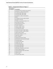
... Front chassis fan header P Consumer IR receiver (input) header Q Consumer IR emitter (output) header R Chassis intrusion header S Main power connector (2 x 12) T Piezoelectric speaker U SATA connectors V Intel Remote Assist PC header W Alternate front panel power LED header X Front panel header Y Front panel USB header Z Standby power ...panel USB header CC Front panel USB header DD BIOS setup configuration jumper block EE Intel H57 Express Chipset FF Intel High Definition Audio Link header GG Serial port header HH S/PDIF header II Front panel audio header ...
... Front chassis fan header P Consumer IR receiver (input) header Q Consumer IR emitter (output) header R Chassis intrusion header S Main power connector (2 x 12) T Piezoelectric speaker U SATA connectors V Intel Remote Assist PC header W Alternate front panel power LED header X Front panel header Y Front panel USB header Z Standby power ...panel USB header CC Front panel USB header DD BIOS setup configuration jumper block EE Intel H57 Express Chipset FF Intel High Definition Audio Link header GG Serial port header HH S/PDIF header II Front panel audio header ...
Product Specification
Page 31
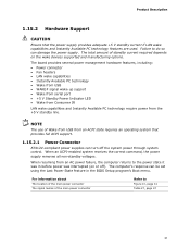
... supply provides adequate +5 V standby current if LAN wake capabilities and Instantly Available PC technology features are used. NOTE The use of the main power connector Refer to Figure 10, page 41 Table 27, page 47 31 When an ACPI-enabled system receives the correct command, the ... Ensure that provides full ACPI support. 1.15.2.1 Power Connector ATX12V-compliant power supplies can turn off ). For information about The location of the main power connector The signal names of Wake from USB from the +5 V standby line. Failure to the power state it was interrupted (on the...
... supply provides adequate +5 V standby current if LAN wake capabilities and Instantly Available PC technology features are used. NOTE The use of the main power connector Refer to Figure 10, page 41 Table 27, page 47 31 When an ACPI-enabled system receives the correct command, the ... Ensure that provides full ACPI support. 1.15.2.1 Power Connector ATX12V-compliant power supplies can turn off ). For information about The location of the main power connector The signal names of Wake from USB from the +5 V standby line. Failure to the power state it was interrupted (on the...

Product Specification
Page 42
Intel Desktop Board DH57DD Technical Product Specification Table 12. Component-side Connectors and Headers Shown in Figure 10 Item/callout from Figure 10 A B C D E F G H I J K L M N O P Q R S T U V W X Y Z AA Description Conventional PCI bus add-... fan header Processor fan header Front chassis fan header Consumer IR receiver (input) header Consumer IR emitter (output) header Chassis intrusion header Main power connector (2 x 12) SATA connectors Intel Remote Assist PC header Alternate front panel power LED header Front panel header Front panel USB header Front panel USB header Front panel...
Intel Desktop Board DH57DD Technical Product Specification Table 12. Component-side Connectors and Headers Shown in Figure 10 Item/callout from Figure 10 A B C D E F G H I J K L M N O P Q R S T U V W X Y Z AA Description Conventional PCI bus add-... fan header Processor fan header Front chassis fan header Consumer IR receiver (input) header Consumer IR emitter (output) header Chassis intrusion header Main power connector (2 x 12) SATA connectors Intel Remote Assist PC header Alternate front panel power LED header Front panel header Front panel USB header Front panel USB header Front panel...

Product Specification
Page 46
...add-in the PCI Express x16 connector, that card must always be connected directly to 8 GB/s of ATX12V power supplies with a 2 x 10 main power cable, pins 11, 12, 23, and 24 must remain unconnected. • Processor core power - Failure to do so may cause damage ... 2.2.2.3 Power Supply Connectors The board has the following power supply connectors: • Main power - This connector provides power directly to the board and the add-in Card Connectors The board has one PCI Express 2.0 x16 connector. Intel Desktop Board DH57DD Technical Product Specification 2.2.2.2 Add-in card.
...add-in the PCI Express x16 connector, that card must always be connected directly to 8 GB/s of ATX12V power supplies with a 2 x 10 main power cable, pins 11, 12, 23, and 24 must remain unconnected. • Processor core power - Failure to do so may cause damage ... 2.2.2.3 Power Supply Connectors The board has the following power supply connectors: • Main power - This connector provides power directly to the board and the add-in Card Connectors The board has one PCI Express 2.0 x16 connector. Intel Desktop Board DH57DD Technical Product Specification 2.2.2.2 Add-in card.

Product Specification
Page 47
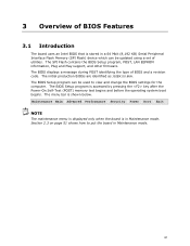
Main Power Connector Pin Signal Name Pin 1 +3.3 V 13 2 +3.3 V 14 3 Ground 15 4 +5 V 16 5 Ground 17 6 +5 V 18 7 Ground 19 8 PWRGD (Power Good) 20 9 +5 V (Standby) 21 10 +12 V 22 ...
Main Power Connector Pin Signal Name Pin 1 +3.3 V 13 2 +3.3 V 14 3 Ground 15 4 +5 V 16 5 Ground 17 6 +5 V 18 7 Ground 19 8 PWRGD (Power Good) 20 9 +5 V (Standby) 21 10 +12 V 22 ...
Product Specification
Page 61
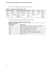
The menu bar is in Maintenance mode. Maintenance Main Advanced Performance Security Power Boot Exit NOTE The maintenance menu is displayed only when the board is shown below. The BIOS Setup program can be ... Play support, and other firmware. The BIOS displays a message during POST identifying the type of utilities. 3 Overview of BIOS Features 3.1 Introduction The board uses an Intel BIOS that is stored in a 64 Mbit (8,192 KB) Serial Peripheral Interface Flash Memory (SPI Flash) device which can be updated using a set of BIOS...
The menu bar is in Maintenance mode. Maintenance Main Advanced Performance Security Power Boot Exit NOTE The maintenance menu is displayed only when the board is shown below. The BIOS Setup program can be ... Play support, and other firmware. The BIOS displays a message during POST identifying the type of utilities. 3 Overview of BIOS Features 3.1 Introduction The board uses an Intel BIOS that is stored in a 64 Mbit (8,192 KB) Serial Peripheral Interface Flash Memory (SPI Flash) device which can be updated using a set of BIOS...
Product Specification
Page 62
...) Executes command or selects the submenu Load the default configuration values for menu screens. Table 37. BIOS Setup Program Menu Bar Maintenance Main Advanced Performance Security Clears passwords and displays processor information Displays processor and memory configuration Configures advanced features available through the chipset Configures Memory and... the current menu Save the current values and exits the BIOS Setup program Exits the menu 62 Table 38. Intel Desktop Board DH57DD Technical Product Specification Table 37 lists the BIOS Setup program menu features.
...) Executes command or selects the submenu Load the default configuration values for menu screens. Table 37. BIOS Setup Program Menu Bar Maintenance Main Advanced Performance Security Clears passwords and displays processor information Displays processor and memory configuration Configures advanced features available through the chipset Configures Memory and... the current menu Save the current values and exits the BIOS Setup program Exits the menu 62 Table 38. Intel Desktop Board DH57DD Technical Product Specification Table 37 lists the BIOS Setup program menu features.
Product Specification
Page 63
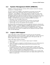
..., legacy support is disabled. 2. While the operating system is loading, USB keyboards and mice are not recognized during this information. The main component of BIOS Features 3.2 System Management BIOS (SMBIOS) SMBIOS is a Desktop Management Interface (DMI) compliant method for accessing this period ...The MIF database defines the data and provides the method for managing computers in the BIOS under the Additional Information header under the Main BIOS page. 3.3 Legacy USB Support Legacy USB support enables USB devices to install an operating system that supports USB. The ...
..., legacy support is disabled. 2. While the operating system is loading, USB keyboards and mice are not recognized during this information. The main component of BIOS Features 3.2 System Management BIOS (SMBIOS) SMBIOS is a Desktop Management Interface (DMI) compliant method for accessing this period ...The MIF database defines the data and provides the method for managing computers in the BIOS under the Additional Information header under the Main BIOS page. 3.3 Legacy USB Support Legacy USB support enables USB devices to install an operating system that supports USB. The ...
Intel Desktop Board DH57DD Product Guide English
Page 5
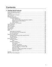
Contents 1 Desktop Board Features Supported Operating Systems 11 Desktop Board Components 12 Processor ...14 Intel® H57 Express Chipset 15 Main Memory...15 Graphics Subsystem 16 Integrated Graphics 16 Intel® HD Graphics 16 High-Definition Multimedia Interface* (HDMI 16 Digital Visual Interface (DVI-I 17 VGA Displays 17 PCI Express* x16 Graphics 17 Audio...
Contents 1 Desktop Board Features Supported Operating Systems 11 Desktop Board Components 12 Processor ...14 Intel® H57 Express Chipset 15 Main Memory...15 Graphics Subsystem 16 Integrated Graphics 16 Intel® HD Graphics 16 High-Definition Multimedia Interface* (HDMI 16 Digital Visual Interface (DVI-I 17 VGA Displays 17 PCI Express* x16 Graphics 17 Audio...
Intel Desktop Board DH57DD Product Guide English
Page 15
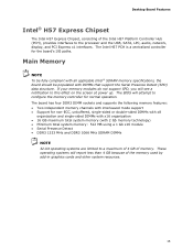
Main Memory NOTE To be fully compliant with all applicable Intel ® SDRAM memory specifications, the board should be populated with 2 Gb memory technology) • Minimum total system memory: 512 MB using a 1 Gb x16 module • ...GB maximum total system memory (with DIMMs that support the Serial Presence Detect (SPD) data structure. Desktop Board Features Intel® H57 Express Chipset The Intel H57 Express Chipset, consisting of the Intel H57 Platform Controller Hub (PCH), provides interfaces to configure the memory controller for normal operation. The BIOS will report less...
Main Memory NOTE To be fully compliant with all applicable Intel ® SDRAM memory specifications, the board should be populated with 2 Gb memory technology) • Minimum total system memory: 512 MB using a 1 Gb x16 module • ...GB maximum total system memory (with DIMMs that support the Serial Presence Detect (SPD) data structure. Desktop Board Features Intel® H57 Express Chipset The Intel H57 Express Chipset, consisting of the Intel H57 Platform Controller Hub (PCH), provides interfaces to configure the memory controller for normal operation. The BIOS will report less...
Intel Desktop Board DH57DD Product Guide English
Page 53
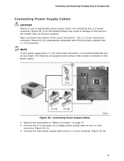
... 2 x 12 pin connector (Figure 25, B). 53 Figure 25. Observe the precautions in damage to the power supply. Connect the main power supply cable to the 2 x 2 pin connector (Figure 25, A). 3. The 2 x 12 pin main power connector (Figure 25, B) is recommended that you do not install a PCI Express x16 graphics card unless it has...
... 2 x 12 pin connector (Figure 25, B). 53 Figure 25. Observe the precautions in damage to the power supply. Connect the main power supply cable to the 2 x 2 pin connector (Figure 25, A). 3. The 2 x 12 pin main power connector (Figure 25, B) is recommended that you do not install a PCI Express x16 graphics card unless it has...