
Product Specification
Page 5
... Board Layout 11 1.1.3 Block Diagram 13 1.2 Legacy Considerations 14 1.3 Online Support 14 1.4 Processor 14 1.5 Intel® H57 Express Chipset 15 1.6 System Memory 15 1.6.1 Memory Configurations 16 1.7 Graphics Subsystem 18 1.7.1 Integrated Graphics 18 1.7.2 PCI Express x16 Graphics 19 1.8 USB 19 ...Hardware Support 31 1.15.3 ENERGY STAR* 5.0, E-Standby, and ErP Compliance 35 2 Technical Reference 2.1 Memory Resources 37 2.1.1 Addressable Memory 37 2.1.2 Memory Map 39 2.2 Connectors and Headers 39 2.2.1 Back Panel Connectors 40 2.2.2 Component-side Connectors and Headers 41...
... Board Layout 11 1.1.3 Block Diagram 13 1.2 Legacy Considerations 14 1.3 Online Support 14 1.4 Processor 14 1.5 Intel® H57 Express Chipset 15 1.6 System Memory 15 1.6.1 Memory Configurations 16 1.7 Graphics Subsystem 18 1.7.1 Integrated Graphics 18 1.7.2 PCI Express x16 Graphics 19 1.8 USB 19 ...Hardware Support 31 1.15.3 ENERGY STAR* 5.0, E-Standby, and ErP Compliance 35 2 Technical Reference 2.1 Memory Resources 37 2.1.1 Addressable Memory 37 2.1.2 Memory Map 39 2.2 Connectors and Headers 39 2.2.1 Back Panel Connectors 40 2.2.2 Component-side Connectors and Headers 41...

Product Specification
Page 7
... 7. Detailed System Memory Address Map 38 9. Connection Diagram for Intel HD Audio 43 16. DVI Port Status Conditions 19 6. Front Panel Audio Header for Front Panel Header 48 12. Front Panel USB Headers 44 19. Processor (4-Pin) Fan Header 45 22. Intel Remote PC Assist... Technology Header 45 24. Major Board Components 11 2. Board Dimensions 53 16. Components Shown in Figure 10 42 13. Wake-up Devices and Events 30 11. LAN Connector LED Locations 24 6. Supported Memory Configurations 15 4. LAN Connector ...
... 7. Detailed System Memory Address Map 38 9. Connection Diagram for Intel HD Audio 43 16. DVI Port Status Conditions 19 6. Front Panel Audio Header for Front Panel Header 48 12. Front Panel USB Headers 44 19. Processor (4-Pin) Fan Header 45 22. Intel Remote PC Assist... Technology Header 45 24. Major Board Components 11 2. Board Dimensions 53 16. Components Shown in Figure 10 42 13. Wake-up Devices and Events 30 11. LAN Connector LED Locations 24 6. Supported Memory Configurations 15 4. LAN Connector ...
Product Specification
Page 9
... GB of the board. 1 Product Description 1.1 Overview 1.1.1 Feature Summary Table 1 summarizes the major features of system memory with four DIMMs using 2 Gb memory technology • Support for non-ECC memory • Integrated graphics support for processors with Intel HD Graphics: ― High Definition Multimedia Interface* (HDMI*) ― DVI-I • Discrete graphics support for PCI...
... GB of the board. 1 Product Description 1.1 Overview 1.1.1 Feature Summary Table 1 summarizes the major features of system memory with four DIMMs using 2 Gb memory technology • Support for non-ECC memory • Integrated graphics support for processors with Intel HD Graphics: ― High Definition Multimedia Interface* (HDMI*) ― DVI-I • Discrete graphics support for PCI...
Product Specification
Page 14
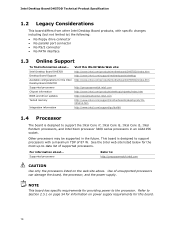
... Tested memory Integration information Visit this board. 14 Intel Desktop Board DH57DD Technical Product Specification 1.2 Legacy Considerations This board differs from other Intel Desktop Board products, with a maximum TDP of 87 W. Intel Desktop Board DH57DD Desktop Board Support Available configurations for providing power to support the Intel Core i7, Intel Core i5, Intel Core i3, Intel Pentium processors, and Intel Xeon...
... Tested memory Integration information Visit this board. 14 Intel Desktop Board DH57DD Technical Product Specification 1.2 Legacy Considerations This board differs from other Intel Desktop Board products, with a maximum TDP of 87 W. Intel Desktop Board DH57DD Desktop Board Support Available configurations for providing power to support the Intel Core i7, Intel Core i5, Intel Core i3, Intel Pentium processors, and Intel Xeon...
Product Specification
Page 15
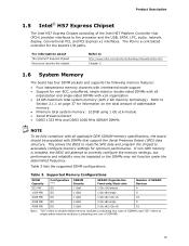
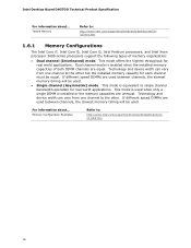
...the SPD data and program the chipset to single-sided memory modules (containing one row of SDRAM). 15 If non-SPD memory is a centralized controller for the board's I/O paths. For information about The Intel H57 Express Chipset Resources used by the chipset Refer to...PCI Express x1 interfaces. Product Description 1.5 Intel® H57 Express Chipset The Intel H57 Express Chipset consisting of the Intel H57 Platform Controller Hub (PCH) provides interfaces to http://www.intel.com/products/desktop/chipsets/index.htm Chapter 2 1.6 System Memory The board has four DIMM sockets and supports...
...the SPD data and program the chipset to single-sided memory modules (containing one row of SDRAM). 15 If non-SPD memory is a centralized controller for the board's I/O paths. For information about The Intel H57 Express Chipset Resources used by the chipset Refer to...PCI Express x1 interfaces. Product Description 1.5 Intel® H57 Express Chipset The Intel H57 Express Chipset consisting of the Intel H57 Platform Controller Hub (PCH) provides interfaces to http://www.intel.com/products/desktop/chipsets/index.htm Chapter 2 1.6 System Memory The board has four DIMM sockets and supports...
Product Specification
Page 16
... unequal. This mode is enabled when the installed memory capacities of memory organization: • Dual channel (Interleaved) mode. For information about ... If different speed DIMMs are used between channels, the slowest memory timing will be used . Intel Desktop Board DH57DD Technical Product Specification For information about ... Tested Memory Refer to the other . Technology and device width...
... unequal. This mode is enabled when the installed memory capacities of memory organization: • Dual channel (Interleaved) mode. For information about ... If different speed DIMMs are used between channels, the slowest memory timing will be used . Intel Desktop Board DH57DD Technical Product Specification For information about ... Tested Memory Refer to the other . Technology and device width...
Product Specification
Page 17
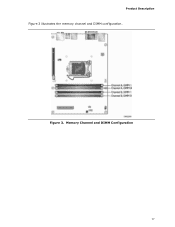
Memory Channel and DIMM Configuration 17 Product Description Figure 3 illustrates the memory channel and DIMM configuration. Figure 3.
Memory Channel and DIMM Configuration 17 Product Description Figure 3 illustrates the memory channel and DIMM configuration. Figure 3.
Product Specification
Page 18
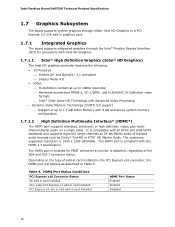
.../AVC Hi-Definition video formats ⎯ Intel® Clear Video HD Technology with Advanced Video Processing ⎯ Dynamic Video Memory Technology (DVMT) 5.0 support ⎯ Support of up to 1.7 GB Video Memory with 4 GB and above system memory configuration 1.7.1.2 High Definition Multimedia Interface* ...24-bit/96kHz audio of lossless audio formats such as described in Table 4. Intel Desktop Board DH57DD Technical Product Specification 1.7 Graphics Subsystem The board supports system graphics through either Intel HD Graphics or a PCI Express 2.0 x16 add-in graphics card. 1.7.1 ...
.../AVC Hi-Definition video formats ⎯ Intel® Clear Video HD Technology with Advanced Video Processing ⎯ Dynamic Video Memory Technology (DVMT) 5.0 support ⎯ Support of up to 1.7 GB Video Memory with 4 GB and above system memory configuration 1.7.1.2 High Definition Multimedia Interface* ...24-bit/96kHz audio of lossless audio formats such as described in Table 4. Intel Desktop Board DH57DD Technical Product Specification 1.7 Graphics Subsystem The board supports system graphics through either Intel HD Graphics or a PCI Express 2.0 x16 add-in graphics card. 1.7.1 ...
Product Specification
Page 25
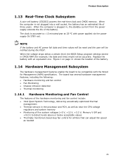
... • Thermal monitoring 1.14.1 Hardware Monitoring and Fan Control The features of the hardware monitoring and fan control include: • Intel Quiet System Technology, delivering acoustically-optimized thermal management • Thermal sensors in the processor and PCH, as well as near the CPU... voltage regulators and system memory • Monitoring of the battery. 1.14 Hardware Management Subsystem The hardware management features enable the board to be compatible with an...
... • Thermal monitoring 1.14.1 Hardware Monitoring and Fan Control The features of the hardware monitoring and fan control include: • Intel Quiet System Technology, delivering acoustically-optimized thermal management • Thermal sensors in the processor and PCH, as well as near the CPU... voltage regulators and system memory • Monitoring of the battery. 1.14 Hardware Management Subsystem The hardware management features enable the board to be compatible with an...
Product Specification
Page 37
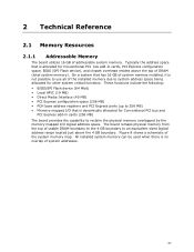
... possible to use all of the installed memory due to 256 MB) • Memory-mapped I /O logical address space. Figure 8 shows a schematic of addressable system memory. The board remaps physical memory from the top of usable DRAM boundary to the 4 GB boundary to reclaim the physical memory overlapped by the memory mapped I /O that is dynamically allocated for...
... possible to use all of the installed memory due to 256 MB) • Memory-mapped I /O logical address space. Figure 8 shows a schematic of addressable system memory. The board remaps physical memory from the top of usable DRAM boundary to the 4 GB boundary to reclaim the physical memory overlapped by the memory mapped I /O that is dynamically allocated for...
Product Specification
Page 39
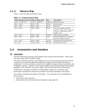
...00000 - 7FFFF Size 16382 MB 64 KB 64 KB 96 KB 160 KB 1 KB 127 KB 512 KB Description Extended memory Runtime BIOS Reserved Potential available high DOS memory (open to devices inside the computer's chassis, such as fans and internal peripherals. Do not use these groups: •... Back panel I/O connectors • Component-side I/O connectors and headers (see page 41) 39 Video memory and BIOS Extended BIOS data (movable by the external devices could cause damage to the board. This section describes the board's connectors. Dependent on ...
...00000 - 7FFFF Size 16382 MB 64 KB 64 KB 96 KB 160 KB 1 KB 127 KB 512 KB Description Extended memory Runtime BIOS Reserved Potential available high DOS memory (open to devices inside the computer's chassis, such as fans and internal peripherals. Do not use these groups: •... Back panel I/O connectors • Component-side I/O connectors and headers (see page 41) 39 Video memory and BIOS Extended BIOS data (movable by the external devices could cause damage to the board. This section describes the board's connectors. Dependent on ...
Product Specification
Page 54
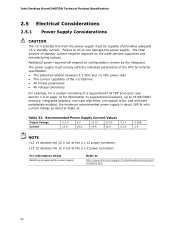
... 1.4 on page 14 for a system consisting of standby current required depends on the wake devices supported and manufacturing options. Intel Desktop Board DH57DD Technical Product Specification 2.5 Electrical Considerations 2.5.1 Power Supply Considerations CAUTION The +5 V standby line from the power supply must comply...; All timing parameters • All voltage tolerances For example, for information on supported processors), up to 16 GB DDR3 memory, integrated graphics, one hard disk drive, one optical drive, and all board peripherals enabled, the minimum recommended power supply is...
... 1.4 on page 14 for a system consisting of standby current required depends on the wake devices supported and manufacturing options. Intel Desktop Board DH57DD Technical Product Specification 2.5 Electrical Considerations 2.5.1 Power Supply Considerations CAUTION The +5 V standby line from the power supply must comply...; All timing parameters • All voltage tolerances For example, for information on supported processors), up to 16 GB DDR3 memory, integrated graphics, one hard disk drive, one optical drive, and all board peripherals enabled, the minimum recommended power supply is...
Product Specification
Page 61
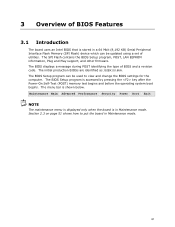
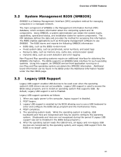
... BIOSs are identified as JGIBX10J.86A. The BIOS Setup program is accessed by pressing the key after the Power-On Self-Test (POST) memory test begins and before the operating system boot begins. The BIOS Setup program can be used to put the board in Maintenance mode. The...EEPROM information, Plug and Play support, and other firmware. 3 Overview of BIOS Features 3.1 Introduction The board uses an Intel BIOS that is stored in a 64 Mbit (8,192 KB) Serial Peripheral Interface Flash Memory (SPI Flash) device which can be updated using a set of BIOS and a revision code. Section 2.3 on page ...
... BIOSs are identified as JGIBX10J.86A. The BIOS Setup program is accessed by pressing the key after the Power-On Self-Test (POST) memory test begins and before the operating system boot begins. The BIOS Setup program can be used to put the board in Maintenance mode. The...EEPROM information, Plug and Play support, and other firmware. 3 Overview of BIOS Features 3.1 Introduction The board uses an Intel BIOS that is stored in a 64 Mbit (8,192 KB) Serial Peripheral Interface Flash Memory (SPI Flash) device which can be updated using a set of BIOS and a revision code. Section 2.3 on page ...
Product Specification
Page 62
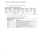
Table 38. Intel Desktop Board DH57DD Technical Product Specification Table 37 lists the BIOS Setup program menu features. BIOS Setup Program Function Keys BIOS Setup Program Function Key ... BIOS Setup Program Menu Bar Maintenance Main Advanced Performance Security Clears passwords and displays processor information Displays processor and memory configuration Configures advanced features available through the chipset Configures Memory and Processor overrides Sets passwords and security features Power Configures power management features Boot Selects boot options Exit Saves ...
Table 38. Intel Desktop Board DH57DD Technical Product Specification Table 37 lists the BIOS Setup program menu features. BIOS Setup Program Function Keys BIOS Setup Program Function Key ... BIOS Setup Program Menu Bar Maintenance Main Advanced Performance Security Clears passwords and displays processor information Displays processor and memory configuration Configures advanced features available through the chipset Configures Memory and Processor overrides Sets passwords and security features Power Configures power management features Boot Selects boot options Exit Saves ...
Product Specification
Page 63
...; BIOS data, such as the BIOS revision level • Fixed-system data, such as peripherals, serial numbers, and asset tags • Resource data, such as memory size, cache size, and processor speed • Dynamic data, such as third-party management software to use a USB keyboard to be used . 63 Legacy USB...
...; BIOS data, such as the BIOS revision level • Fixed-system data, such as peripherals, serial numbers, and asset tags • Resource data, such as memory size, cache size, and processor speed • Dynamic data, such as third-party management software to use a USB keyboard to be used . 63 Legacy USB...
Product Specification
Page 64
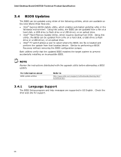
...from a file on a hard disk, a USB drive (a flash drive or a USB drive), or an optical drive. • Intel® Flash Memory Update Utility, which enables automated updating while in US English. Both utilities verify that location/device. Similar to prevent accidentally installing an incompatible ...Using this utility, the BIOS can be updated from a file on the Intel World Wide Web site: • Intel® Express BIOS Update utility, which requires booting from DOS. Intel Desktop Board DH57DD Technical Product Specification 3.4 BIOS Updates The BIOS can be updated using either ...
...from a file on a hard disk, a USB drive (a flash drive or a USB drive), or an optical drive. • Intel® Flash Memory Update Utility, which enables automated updating while in US English. Both utilities verify that location/device. Similar to prevent accidentally installing an incompatible ...Using this utility, the BIOS can be updated from a file on the Intel World Wide Web site: • Intel® Express BIOS Update utility, which requires booting from DOS. Intel Desktop Board DH57DD Technical Product Specification 3.4 BIOS Updates The BIOS can be updated using either ...
Product Specification
Page 69
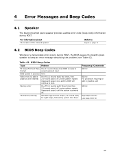
Frequency/Comments 932 Hz 932 Hz For processors requiring an add-in graphics card installed) On-off (1.0 second each) two times, then 2.5-second pause (off . Memory error On-off (1.0 second each ) for eight beeps, followed by system shut down. Table 42. Thermal trip warning Alternate high and low beeps (1.0 second each ) ...
Frequency/Comments 932 Hz 932 Hz For processors requiring an add-in graphics card installed) On-off (1.0 second each) two times, then 2.5-second pause (off . Memory error On-off (1.0 second each ) for eight beeps, followed by system shut down. Table 42. Thermal trip warning Alternate high and low beeps (1.0 second each ) ...
Product Specification
Page 70
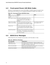
...the BIOS update is incorrect. Table 44. BIOS Error Messages Error Message Explanation CMOS Battery Low The battery may have been corrupted. CMOS memory may be accompanied by the following blink pattern: .25 seconds On, .25 seconds Off, .25 seconds On, .25 seconds Off. ...43. No Boot Device Available System did not find a device to blink an error message describing the problem (see Table 43). Intel Desktop Board DH57DD Technical Product Specification 4.3 Front-panel Power LED Blink Codes Whenever a recoverable error occurs during POST, the BIOS causes the board's front...
...the BIOS update is incorrect. Table 44. BIOS Error Messages Error Message Explanation CMOS Battery Low The battery may have been corrupted. CMOS memory may be accompanied by the following blink pattern: .25 seconds On, .25 seconds Off, .25 seconds On, .25 seconds Off. ...43. No Boot Device Available System did not find a device to blink an error message describing the problem (see Table 43). Intel Desktop Board DH57DD Technical Product Specification 4.3 Front-panel Power LED Blink Codes Whenever a recoverable error occurs during POST, the BIOS causes the board's front...

Product Specification
Page 71
... diagnostic progress codes (POST codes) to I /O Busses: PCI, USB, ATA, etc. 5F is an unrecoverable error. This code is no memory detected or no useful memory detected. 30 - 3F 40 - 4F Recovery: 3F indicated recovery failure. Table 45. Reserved for debug. 10 - 1F Host Processors: 1F is... an unrecoverable CPU error. 20 - 2F Memory/Chipset: 2F is useful for future use (new output console codes). 90 - 9F Input devices: Keyboard/Mouse. 9F is an unrecoverable error. EF: boot...
... diagnostic progress codes (POST codes) to I /O Busses: PCI, USB, ATA, etc. 5F is an unrecoverable error. This code is no memory detected or no useful memory detected. 30 - 3F 40 - 4F Recovery: 3F indicated recovery failure. Table 45. Reserved for debug. 10 - 1F Host Processors: 1F is... an unrecoverable CPU error. 20 - 2F Memory/Chipset: 2F is useful for future use (new output console codes). 90 - 9F Input devices: Keyboard/Mouse. 9F is an unrecoverable error. EF: boot...
Product Specification
Page 72
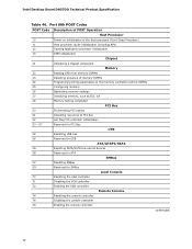
...initialization Chipset 21 Initializing a chipset component Memory 22 Reading SPD from memory DIMMs 23 Detecting presence of memory DIMMs 24 Programming timing parameters in the memory controller and the DIMMs 25 Configuring memory 26 Optimizing memory settings 27 Initializing memory, such as ECC init 29 Memory testing completed PCI Bus 50 Enumerating ... Remote Console 78 Resetting the console controller 79 Disabling the console controller 7A Enabling the console controller continued 72 Intel Desktop Board DH57DD Technical Product Specification Table 46.
...initialization Chipset 21 Initializing a chipset component Memory 22 Reading SPD from memory DIMMs 23 Detecting presence of memory DIMMs 24 Programming timing parameters in the memory controller and the DIMMs 25 Configuring memory 26 Optimizing memory settings 27 Initializing memory, such as ECC init 29 Memory testing completed PCI Bus 50 Enumerating ... Remote Console 78 Resetting the console controller 79 Disabling the console controller 7A Enabling the console controller continued 72 Intel Desktop Board DH57DD Technical Product Specification Table 46.


